

Form 6-K ENERGY FUELS INC For: Mar 19
 Tweet
Tweet Share
ShareUNITED STATES
SECURITIES AND EXCHANGE COMMISSION
Washington, D.C. 20549
Form 6-K
REPORT OF FOREIGN PRIVATE ISSUER PURSUANT TO RULE
13a-16 or 15d-16 UNDER THE
SECURITIES EXCHANGE ACT OF 1934
For the month of March, 2015.
Commission File Number 001-36204
ENERGY FUELS INC.
(Translation of registrant’s name into English)
225 Union Blvd., Suite 600
Lakewood, CO 80228
(Address of principal executive offices)
Indicate by check mark whether the registrant files or will file annual reports under cover Form 20-F or Form 40-F
Form 20-F [ ] Form 40-F [X]
Indicate by check mark if the registrant is submitting the Form 6-K in paper as permitted by Regulation S-T Rule 101(b)(1): [ ]
Note: Regulation S-T Rule 101(b)(1) only permits the submission in paper of a Form 6-K if submitted solely to provide an attached annual report to security holders.
Indicate by check mark if the registrant is submitting the Form 6-K in paper as permitted by Regulation S-T Rule 101(b)(7): [ ]
Note: Regulation S-T Rule 101(b)(7) only permits the submission in paper of a Form 6-K if submitted to furnish a report or other document that the registrant foreign private issuer must furnish and make public under the laws of the jurisdiction in which the registrant is incorporated, domiciled or legally organized (the registrant’s “home country”), or under the rules of the home country exchange on which the registrant’s securities are traded, as long as the report or other document is not a press release, is not required to be and has not been distributed to the registrant’s security holders, and, if discussing a material event, has already been the subject of a Form 6-K submission or other Commission filing on EDGAR.
SIGNATURE
Pursuant to the requirements of the Securities Exchange Act of 1934, the registrant has duly caused this report to be signed on its behalf by the undersigned, thereunto duly authorized.
| ENERGY FUELS INC. | |
| /S/ David C. Frydenlund | |
| Date: March 19, 2015 | David C. Frydenlund |
| Senior Vice President, General Counsel & Corporate | |
| Secretary |
-2-
INDEX TO EXHIBITS
-3-
NI 43-101 Technical Report on
Resources Wate Uranium Breccia
Pipe – Northern Arizona, USA.
Report Prepared for
Energy Fuels Resources (USA), Inc.
And
Uranium One Inc.
Report Prepared by
SRK Consulting (U.S.), Inc.
357600.030
March 10, 2015
| SRK Consulting | |
| NI 43-101 Technical Report on Resources Wate Uranium Breccia Pipe – Northern Arizona, USA. | Page i |
NI 43-101 Technical Report on Resources Wate
Uranium
Breccia Pipe – Northern Arizona, USA
Energy Fuels Resources (USA) Inc.
225 Union Blvd.,
Suite 600
Lakewood, CO., U.S.
And
Uranium One Inc.
25 Adelaide St. E., Suite 1616
Toronto, Ontario, M5C 3A1
SRK Consulting (U.S.), Inc.
3275 West Ina Road,
Suite 240
Tucson, AZ 85741
e-mail: [email protected]
website: www.srk.com
Tel: 1.520 544 3688
Fax: 1.520 544 9853
SRK Project
Number 357600.030
March 10, 2015
Authors and Qualified Persons:
Allan Moran, C.P.G.
AIPG
Associate Principal Consultant (Geology)
Frank A. Daviess, MAusIM, RM SME
Associate Principal
Consultant (Resource Geology)
Peer Reviewed by:
Corolla Hoag, C.P.G. AIPG
Principal Consultant (Geology)
| FD/AVM/CKH | March 2015 |
| SRK Consulting | |
| NI 43-101 Technical Report on Resources Wate Uranium Breccia Pipe – Northern Arizona, USA. | Page ii |
Summary (Item 1)
Energy Fuels Resources (US) Inc. (Energy Fuels) controls the Wate Uranium Breccia Pipe (the Project), located in northern Arizona. The Project is a mid-stage exploration property with established Inferred uranium resources of 71,000 tons grading 0.79% eU3O8 for 1,118,000 contained pounds eU3O8 (Table 20-2). The Wate Pipe is one of several uranium bearing breccia pipe properties held by Energy Fuels in northern Arizona, which include properties in the exploration, development, and active mining stage. The Wate Pipe had historical drilling and resource estimates, and VANE Minerals (US) LLC (VANE) conducted verification drilling and gamma logging to confirm the historical data and allow for resource estimation for the mineralized breccia pipe during the period of 2008 through 2011. Section 16 further describes current resources that are the subject of this report. The Wate Pipe is an attractive high-grade uranium deposit that justifies further exploration and/or pre-development work.
In February of 2015, Energy Fuels, through its wholly-owned subsidiary EFR Arizona Strip LLC, acquired VANE’s 50% interest in the Project. The Project is held by the Wate Mining Company LLC joint venture (the “LLC”) between VANE and Uranium One Americas, Inc. (U1), and U1 continues to own 50% of the LLC. Energy Fuels will assume VANE’s role as Manager of the LLC.
The Wate Uranium Breccia Pipe is located in northwestern Arizona, south of the Grand Canyon National Park in Coconino County. Prior owners advanced the Wate Pipe to the point of internal feasibility study during the 1980’s, although the depressed uranium market at the time resulted in the abandonment of the properties and the dissolution of the companies. The Wate Pipe, acquired through the Agreement with U1, had previously been evaluated with sufficient drill results to be considered by the former owner, Rocky Mountain Energy Partners, L.P. (RME), as a mineral resource (historical term not compliant with current resource classifications) sufficient for internal pre-development consideration. VANE acquired the readily available historical exploration information for the Project in 2008. Uranium mineralization is typical of past producing uranium breccia pipe deposits in Arizona, which had grades near 1.0% U3O8 and from 1 to 6 M lbs. of contained U3O8. Mineralization typically occurs at depths of about 600 ft. to 2,000 ft. in a vertical, narrow, cylindrical breccia body that can have dimensions of 300 ft. across or less.
This report is a NI 43-101 Technical Report on resources for the Wate Uranium Breccia Pipe, for Energy Fuels, specifically to reflect the change in ownership; mineral resources have not changed since reported for VANE in 2011. The mineral resources are still current. VANE confirmed high grade intercepts at Wate by re-entering and re-logging (gamma logs) some of the historical drillholes, and by drilling several new drillholes. VANE confirmed (through re-logging of historical drillholes) an intercept of 34 ft. @ 1.67% eU3O8, from 1,489 to 1,523 ft. in depth in drillhole WT-5 and 10.5 ft. @ 0.40% eU3O8 from 1,244.5 to 1,255.0 ft. in depth in drillhole WT-7. VANE drilling/logging results from eight of eleven new drillholes has defined mineralization of similar grades and thicknesses to that in historical holes. The key drillhole intercepts upon which the current resource for the Wate Pipe is estimated, are listed in Table 20-1:
| FD/AVM/CKH | March 2015 |
| SRK Consulting | |
| NI 43-101 Technical Report on Resources Wate Uranium Breccia Pipe – Northern Arizona, USA. | Page iii |
Table 20-1: Significant Drill intercepts for the Wate Pipe at 0.15% eU3O8 cutoff
| WT-29A
upper |
WT- 29A lower |
WT-33 | WT- 34 | WT-35 (cum) |
WT-37 upper |
WT-37
middle |
WT-37 lower |
WT-39
(un-cut) |
WT-41 | Wt-42 (cum) |
WT-5 | WT-7 | |
| Thickness (ft) | 36.0 | 28.0 | 25.5 | 15.0 | 21.5 | 20.0 | 2.5 | 12.5 | 64.5 | 27 | 35.5 | 32.5 | 9.0 |
| Ave Grade (%U3O8) |
0.69 | 1.60 | 0.45 | 0.30 | 0.33 | 0.37 | 0.19 | 1.29 | 1.45** | 1.45 | 0.25 | 1.52 | 0.47 |
| No 0.5 ft interval |
72 | 56 | 51 | 30 | 31 | 40 | 5 | 25 | 129 | 54 | 71 | 65 | 18 |
| No. > 0.5% eU3O8 |
34 | 49 | 22 | 0 | 6 | 10 | 0 | 20 | 101 | 36 | 4 | 45 | 7 |
| High value (%eU3O8) |
2.47 | 4.61 | 0.97 | 0.48 | 0.69 | 1.39 | 0.25 | 3.18 | 18.35* | 2.92 | 1.12 | 4.38 | 1.21 |
| from (ft) | 1318.0 | 1498.5 | 1421.0 | 1269.5 | 1333.5 | 1299.0 | 1328.0 | 1362.5 | 1448 | 1453.5 | 1246 | 1483.5 | 1242.5 |
| to (ft) | 1354.0 | 1526.5 | 1446.5 | 1284.5 | 1370.0 | 1319.0 | 1330.5 | 1375.0 | 1512.5 | 1480.5 | 1599.5 | 1516.0 | 1251.5 |
| GT (Ft-%) | 24.7 | 44.7 | 11.5 | 4.5 | 7.1 | 7.3 | 0.5 | 16.1 | 93.6 | 39.1 | 8.71 | 49.3 | 4.3 |
Note: WT-35 and WT-42 represent
cumulative intercept intervals; WT-5 and WT-7 are re-logs of historical holes
WT-36 , WT-38, and WT-40 did not encounter +0.15% mineralization
* Two
0.5 ft intervals at 10.3% and 18.4%,
respectively in WT-39
** Two 0.5 ft intervals
capped at 7.0% in WT-39 - results in 1.29%
average grade
| FD/AVM/CKH | March 2015 |
| SRK Consulting | |
| NI 43-101 Technical Report on Resources Wate Uranium Breccia Pipe – Northern Arizona, USA. | Page iv |
History
The Arizona Uranium Breccia Pipe District was prospected for uranium in the 1950s and again in late 1970s, after uranium was discovered in copper bearing breccias, such as those in the Orphan Mine in the Grand Canyon. This region produced approximately 23 M lbs of U3O8 prior to the decline of uranium prices in the late 1980s. Most deposits are small to intermediate in size, with a typical breccia pipe having dimensions of 300 ft. in diameter and 2,000 ft. or more vertically.
The Wate Pipe contains several drill holes with + 0.50%, eU3O8 mineralization grades and an exploration potential (historically estimated resources) of between 70,000 tons grading 0.80% eU3O8 (1.1 million contained pounds eU3O8), and 146,000 tons grading 0.83% eU3O8 (2.4 million contained pounds eU3O8). This exploration potential, or historically reported non-CIM-compliant resources/reserves for the Wate Pipe, cannot be relied upon until adequately demonstrated with sufficient drilling. Historical drilling encountered reported “ore grade” mineralization in 17 of 23 drillholes.
Geology
The high-grade uranium deposits in breccia pipes in northern Arizona were deposited in solution-collapse features that originated in the Mississippian Redwall Limestone and propagated upward through the overlying Pennsylvanian and Permian redbeds and sandstones during several periods of karstification. Uranium was deposited after karstification.
As uranium dissolved in groundwater moved northward from southern Arizona through the sandstones during the early Mesozoic (~200 Ma), it was channeled by the impermeable layers above and below the sandstones. Uranium minerals precipitated in reducing environments influenced by the pre-existing sulfides or hydrocarbon-bearing material present in the limestones, shales, siltstones, and sandstones. This results in concentrations of uranium mineralization in the open space of near vertical sub-cylindrical breccia bodies, which occur in sections of the nearly flat-lying upper Paleozoic sedimentary rocks that comprise the Colorado Plateau on both sides of the Grand Canyon.
Resources – Wate Pipe
The Wate Pipe had an internal company-derived mineral resource completed in the late 1980s, which is not compliant with current CIM standards for reporting mineral resources. VANE gathered the historical information in 2008, conducted drillhole validations through re-entering historical drillholes and re-logging (gamma-logs) in 2009 and 2010, and drilled several new drillholes in 2010. Not all the historical information is available, yet there is sufficient drillhole information to allow for definition of mineralized shapes for the historically defined mineralization. SRK modeled the mineralization in four discrete zones within the Wate Pipe, and completed resource estimation by industry standard procedures that are compliant with CIM definitions for NI 43-101 reporting.
| FD/AVM/CKH | March 2015 |
| SRK Consulting | |
| NI 43-101 Technical Report on Resources Wate Uranium Breccia Pipe – Northern Arizona, USA. | Page v |
Table 20-2: Current Inferred Resources for the Wate Pipe at 0.15%eU3O8cutoff
| Wate Breccia Pipe
Inferred Resource 0.15% eU3O8 Cutoff* | |||||
| Zone | Cutoff | U3O8% | Tons (000) | lb-U3O8 (000) | |
| 1 | 0.15 | 0.84 | 58 | 971 | |
| 2 | 0.15 | 0.61 | 11 | 130 | |
| 3 | 0.15 | 0.31 | 2 | 10 | |
| 4 | 0.15 | 0.58 | 1 | 7 | |
| 0.79 | 71 | 1,118 | |||
* Note: Inferred Uranium resources refers to global in-place CIM definitions of resources to which a mine design has not yet been applied; although the above stated resources meet the definition of having the “potential for economic extraction” at the cutoff provided. Resources are current, effective as of March 22, 2011, the date of the most recent drilling information.
A 0.15% eU3O8 cutoff equates to an in-place dollar value per ton, at a $38/lb U3O8 price, of $114/ton; deemed more than sufficient to cover the cost of mining and processing a ton of material. The natural lower threshold of mineralization in the Wate Pipe is approximately 0.15% eU3O8 as well. Both suggest that a 0.15% cutoff grade is acceptable for Wate.
Property, Mining Rights, and Location
Through acquisition of VANE’s interests in Wate Mining LLC, Energy Fuels is the current Manager of the Property. Energy Fuels and joint venture partner U1 hold the Project property through a state mineral exploration permit on Arizona State lands, which is in the process of conversion to a mining lease.
Exploration/Development Potential
The SRK estimate of resources for the Wate Uranium Breccia Pipe is conservative with respect to historical estimates of tonnage, yet similar in grade, in large part due to the minimal amount of historical drilling data available for the Project. VANE acquired historical reports that state the intercepts in all historical drillholes; however, the gamma logs and geological logs that back up the historical intercept data were not available to VANE. Therefore, SRK used the historical intercept data, some of which has been verified by VANE re-logging, to generate the mineralized shapes within which resource estimation was done using only VANE generated data. In SRK’s opinion, further drilling or acquisition (if possible) of the historical data will allow for a better estimate of the in-situ resources and the potential of increasing the total tonnage and contained pounds of uranium mineralization. Section 16 discusses this further.
Mining
Underground mining methods are typically used for uranium breccia pipes (Wenrich and others, 1995). Historically mined breccia pipes north of the Grand Canyon were accessed by shaft and decline, and were mined by standard open-stope methods.
The Wate Project is near the stage of mining considerations, as resources are defined; however, drilling confirmation of additional historical drillholes will provide greater confidence in the current resource. SRK understands that Energy Fuels and venture partner U1 may seek to complete additional confirmation drilling. The Wate Pipe could advance rapidly from resource estimate to underground exploration and development planning within a six-to-twelve month period without further confirmation drilling.
| FD/AVM/CKH | March 2015 |
| SRK Consulting | |
| NI 43-101 Technical Report on Resources Wate Uranium Breccia Pipe – Northern Arizona, USA. | Page vi |
Metallurgy and Processing
This Project has had no mineral processing or metallurgical testing done, however core samples have been assembled by VANE for this purpose. Historical mining of this deposit type in Arizona developed ores processed by conventional uranium milling technology. Historically, ore was shipped to a mill in Tuba City, AZ, and in the 1980s, uranium ores were shipped to the White Mesa mill in Blanding, Utah. The Shootaring Mill, located in southeastern Utah and owned by Uranium One, was constructed in the 1980s and operated on a test basis. The White Mesa mill, owned and opearated by Energy Fuels is in operation. It is anticipated that future production from the Wate Pipe would be processed at Energy Fuel’s White Mesa mill in Utah; a distance by road for truck-hauling of approximately 390 miles.
Milled uranium ore is processed by either acid or alkaline solutions, and uranium is precipitated by either ion-exchange or solvent extraction – industry standard processes. The product, commonly ammonium diuranate, is called “yellowcake” because of its color (Cooper, 1986).
Infrastructure
The portion of the Colorado Plateau south of the Grand Canyon has excellent infrastructure (roads and power) and an established diverse mining industry with a history of past uranium production.
Environmental/Permitting
SRK is unaware of any environmental liabilities for the Project with respect to additional exploration drilling at the Wate Pipe. The author is not a Qualified Person with respect to environmental issues. However, a brief site visit indicated there was little disturbance to the ground by previous drilling. Drillholes from the 1980s were only discovered because the capped drill casing extended above the soil by at least 6 inches; in other cases, there was no surface sign of drillholes other than scattered drill cuttings. The footprint of the breccia pipe exploration targets and historical mines are quite small, easily being located on about 25 acres. Permitting at this stage of the Project is handled as Plans of Operations through the Arizona State Land Department.
U1 initiated, and VANE completed a Mineral Development Report (MDR) for submission to the Arizona State Land Department. The MDR addresses, at scoping level of study, the mining processing and eventual closure and reclamation of the Project, for the purpose of obtaining a mining lease with an established production royalty rate payable to the state of Arizona. The MDR is reportedly in the final stages of approval (pers. Comm. K. Hefton, 2015) by the Arizona State Land Department. Approval of the MDR will allow for commercial mining, subject to obtaining requires environmental permits.
Conclusions and Recommendations
The VANE-U1 joint venture’s exploration expenditures from November 2008 to the completion of drilling (March 2011) on the Project is approximately US$1,364,000; primarily for drilling.
The Project represents an attractive advanced-stage exploration property with current estimated resources established of over 1.0 million pounds eU3O8, and the potential to increase the total resource tons and contained pounds with additional confirmation drilling. Energy Fuels considers the mineral resources at the Wate Pipe to be sufficiently as a minimum threshold for a decision to proceed underground to allow for detailed drill definition of the resources.
The Project has all the inherent opportunity and/or risk associated with a resource stage property, including quantity and quality of the resource database, commodity price fluctuations, defining metallurgical characteristics, and addressing permitting and potential mining options.
SRK recommends an additional drilling program to advance the Project to a point of maximum resource definition, and the potential for project development. This can best be accomplished by additional drilling from an exploration shaft rather than by drilling from surface.
| FD/AVM/CKH | March 2015 |
| SRK Consulting | |
| NI 43-101 Technical Report on Resources Wate Uranium Breccia Pipe – Northern Arizona, USA. | Page vii |
Prior to committing to an exploration shaft, SRK recommends a scoping level study and preliminary economic assessment to determine the potential economic viability of the project and the break-even resource to justify a decision to go underground.
| FD/AVM/CKH | March 2015 |
| SRK Consulting | |
| NI 43-101 Technical Report on Resources Wate Uranium Breccia Pipe – Northern Arizona, USA. | Page viii |
Table of Contents
| Summary (Item 1) | ii | |||
| 1 | Introduction (Item 2) | 1 | ||
| 1.1 | Terms of Reference and Purpose of the Report | 1 | ||
| 1.1.1 | Sources of Information | 1 | ||
| 1.1.2 | Terms of Reference | 1 | ||
| 1.1.3 | Definitions of Terms | 2 | ||
| 1.1.4 | Purpose of Report | 2 | ||
| 1.1.5 | Conclusions and Recommendations | 2 | ||
| 1.2 | Sources of Information | 2 | ||
| 1.3 | Mineral Resources Statements | 2 | ||
| 1.4 | Qualifications of Consultants (SRK) and Site Visit | 2 | ||
| 1.5 | Effective Date | 3 | ||
| 2 | Reliance on Other Experts (Item 3) | 4 | ||
| 3 | Property Location and Description (Item 4) | 5 | ||
| 3.1 | Property Location | 5 | ||
| 3.2 | Mineral Titles | 5 | ||
| 3.2.1 | Mineral Rights in Arizona | 5 | ||
| 3.2.2 | Requirements to Maintain the Claims in Good Standings | 5 | ||
| 3.2.3 | Mining Venture Agreement | 6 | ||
| 3.2.4 | Exceptions to Title Option | 6 | ||
| 3.3 | Royalty Agreements and Encumbrance | 6 | ||
| 3.3.1 | Required Permits and Status | 7 | ||
| 3.4 | Environmental Liabilities | 7 | ||
| 4 | Accessibility, Climate, Local Resources, Infrastructure and Physiography (Item 5)10 | |||
| 4.1 | Access to Properties | 10 | ||
| 4.2 | Climate | 10 | ||
| 4.2.1 | Vegetation | 10 | ||
| 4.3 | Physiography | 10 | ||
| 4.4 | Local Resources and Infrastructure | 11 | ||
| 4.4.1 | Access Road | 11 | ||
| 4.4.2 | Water Supply | 11 | ||
| 4.4.3 | Electrical Power Supply | 11 | ||
| 4.4.4 | Buildings and Ancillary Facilities | 11 | ||
| 4.4.5 | Population | 11 | ||
| 4.4.6 | Economy | 11 | ||
| FD/AVM/CKH | March 2015 |
| SRK Consulting | |
| NI 43-101 Technical Report on Resources Wate Uranium Breccia Pipe – Northern Arizona, USA. | Page ix |
| 4.4.7 | Local Resources | 12 | ||
| 4.4.8 | Regional Infrastructure | 12 | ||
| 5 | History (Item 6) | 14 | ||
| 5.1 | Ownership | 14 | ||
| 5.1.1 | Wate Pipe | 14 | ||
| 5.1.2 | Project Expenditures | 15 | ||
| 5.2 | Historic Mineral Resource Estimates | 15 | ||
| 6 | Geologic Setting (Item 7) | 18 | ||
| 6.1 | Regional Geology | 18 | ||
| 6.1.1 | Geology of Breccia Pipes | 18 | ||
| 6.1.2 | Other Productive Uranium Breccia Pipes in the Region | 20 | ||
| 6.2 | Local Geology | 21 | ||
| 6.2.1 | Local Lithology | 21 | ||
| 6.2.2 | Alterations | 23 | ||
| 6.2.3 | Structure | 23 | ||
| 6.2.4 | Mineralization | 23 | ||
| 7 | Deposit Types (Item 8) | 28 | ||
| 8 | Exploration (Item 9) | 29 | ||
| 8.1 | Wate Pipe – VANE Exploration | 29 | ||
| 8.2 | Geophysical Surveys | 29 | ||
| 8.3 | Summary | 30 | ||
| 9 | Drilling (Item 10) | 33 | ||
| 9.1 | Drill Results from Wate Pipe | 34 | ||
| 9.2 | Planned Drilling | 35 | ||
| 9.3 | Recommendations | 35 | ||
| 10 | Sampling Preparation, Analysis and Security (Item 11) | 39 | ||
| 10.1 | RC/Rotary/ Spot Core Drilling | 39 | ||
| 10.2 | Wireline Diamond Core Drilling | 39 | ||
| 10.3 | Gamma Logging | 39 | ||
| 10.4 | Analytical Procedures | 40 | ||
| 10.5 | Sample Preparation and Assaying | 40 | ||
| 10.6 | Quality Controls and Quality Assurance | 40 | ||
| 10.7 | Sample Security | 40 | ||
| 10.8 | Analytical Laboratory Certification | 41 | ||
| 10.9 | Radiometric Analyses | 41 | ||
| 11 | Data Verification (Item 12) | 44 | ||
| FD/AVM/CKH | March 2015 |
| SRK Consulting | |
| NI 43-101 Technical Report on Resources Wate Uranium Breccia Pipe – Northern Arizona, USA. | Page x |
| 12 | Mineral Processing and Metallurgical Testing (Item 13) | 46 | ||
| 13 | Mineral Resource Estimate (Item 14) | 47 | ||
| 13.1 | Drillhole Database | 47 | ||
| 13.2 | Assay Data – Population Domain Analysis | 52 | ||
| 13.3 | Mineralization Envelopes | 54 | ||
| 13.4 | Composition | 59 | ||
| 13.5 | Specific Gravity Measurements (Bulk Density) | 59 | ||
| 13.6 | Block Models | 59 | ||
| 13.7 | Mineralization Zones | 59 | ||
| 13.8 | Dynamic Anisotropy and Search Orientation | 60 | ||
| 13.9 | Mineralization Indicator Assignment, Zones 2-4 | 61 | ||
| 13.10 | Domain Assignment, Zone 1 | 61 | ||
| 13.11 | Grade Estimation and Resource Classification Criteria | 64 | ||
| 13.12 | Block Model Validation & Mineral Resource Sensitivity | 69 | ||
| 13.13 | Resource Statement | 69 | ||
| 13.14 | Sensitivity of the Resource Model | 70 | ||
| 13.15 | Conclusions and Recommendations | 70 | ||
| 14 | Items 15 through 22) | 69 | ||
| 15 | Adjacent Properties (Item 23) | 70 | ||
| 16 | Other Relevant Data and Information (Item 24) | 71 | ||
| 17 | Interpretation and Conclusion (Item 25) | 73 | ||
| 17.1 | Categories of Opportunity and Risk | 73 | ||
| 17.1.1 | Resources | 73 | ||
| 17.1.2 | Commodity Price Fluctuation | 73 | ||
| 17.1.3 | Infrastructure | 73 | ||
| 17.1.4 | Development Decision | 73 | ||
| 17.1.5 | Metallurgical Characteristics | 74 | ||
| 17.1.6 | Environmental/Socio-Economic Considerations | 74 | ||
| 18 | Recommendations (Item 26) | 75 | ||
| 18.1 | Proposed Scoping Study – Phase I | 75 | ||
| 18.2 | Phase II | 75 | ||
| 19 | References (Item 27) | 77 | ||
| 20 | Glossary (Item 27) | 79 | ||
| List of Abbreviations | 80 | |||
| FD/AVM/CKH | March 2015 |
| SRK Consulting | |
| NI 43-101 Technical Report on Resources Wate Uranium Breccia Pipe – Northern Arizona, USA. | Page xi |
List of Tables
| Table 1-1: | Significant Drill intercepts for the Wate Pipe at 0.15% eU3O8 cutoff | iii |
| Table 1-2: | Current Inferred Resources for the Wate Pipe at 0.15% eU3O8 cutoff | v |
| Table 4-1: | Physiography of Wate Pipe Area | 11 |
| Table 5-1: | May 2010 Inferred Resources for the Wate Pipe at 0.15% eU3O8 cutoff | 16 |
| Table 5-2: | May 2010 Inferred Resources for the Wate Pipe at 0.15% eU3O8 cutoff | 16 |
| Table 9-1: | Summary of VANE Drilling Wate Breccia Pipe | 34 |
| Table 9-2: | Summary of VANE Drilling (including washouts of historical holes) | 35 |
| Table 11-1: | Comparison of Historical and VANE re-logs for WT-5 and WT-7 | 45 |
| Table 13-1: | Selected Historical Drillhole Intercepts – Wate Pipe | 50 |
| Table 3-2: | Drillhole Database Statistics – VANE Drillholes (SRK, April 2011) | 51 |
| Table 13-3: | Wate Pipe Zone 1 Grade Population Cutoff Thresholds | 54 |
| Table 13-4: | Zone 1 Composite Summary Statistics | 59 |
| Table 13-5: | Wate Pipe Model Limits | 59 |
| Table 13-6: | Estimation Parameters (Domain 0) | 64 |
| Table 13-7: | Estimation Parameters (Domain 1) | 66 |
| Table 13-8: | Contiguous 0.5ft Higher-Grade intercepts WT-05 & WT-29A | 69 |
| Table 13-9: | Inferred Resource by Zone & Total | 69 |
List of Figures
| Figure 3-1: | Energy Fuels Uranium Breccia Pipe Project Location Map | 8 |
| Figure 3-2: | Location of Wate Pipe. Section 32, T31N R5W (SRK 2010) | 9 |
| Figure 4-1: | Regional Access Roads and Surface Land Ownership in Vicinity of the Wate Pipe | 13 |
| Figure 5-1: | Plan Map and Drillhole traces of Historic Drillholes at the Wate Breccia Pipe (2008) | 17 |
| Figure 6-1: | Geologic Map of Arizona | 25 |
| Figure 6-2: | Stratigraphic Position of Ore in Uranium Breccia Pipes | 26 |
| Figure 6-3: | Characteristics of Uranium Breccia Pipes, Northern Arizona | 27 |
| Figure 8-1: | Wate Pipe Looking Southwest (January 2009) | 31 |
| Figure 8-2: | Typical Breccia Pipe Surface Expression - Miller Pipe Looking Southwest | 32 |
| Figure 9-1: | Locations of VANE and Historic Drillholes at the Wate Breccia Pipe | 37 |
| Figure 9-2: | Sketch Cross Section – Wate Pipe Historical Drillholes | 38 |
| Figure 10-1: | Example Gamma Log -- Half-Amplitude Method | 43 |
| Figure 13-1: | Cross Section of Historical and VANE drillholes (SRK 2011 | 48 |
| Figure 13-2: | Cross Section of Historical and VANE drillholes (SRK 2011) | 49 |
| Figure 13-3: | Wate Pipe Cumulative Relative Frequency Distribution (SRK 2011) | 52 |
| Figure 13-4: | Cross-Section of Mineralized Drillholes and 2-D strings (SRK 2010) | 55 |
| FD/AVM/CKH | March 2015 |
| SRK Consulting | |
| NI 43-101 Technical Report on Resources Wate Uranium Breccia Pipe – Northern Arizona, USA. | Page xii |
| Figure 13-5: | Oblique View of 2010 Mineralized Shape (SRK 2010) | 56 |
| Figure 13-6: | Oblique View of 2010 Mineralized Shape (SRK 2010) | 57 |
| Figure 13-7: | Plan View delineation (SRK 2011) | 57 |
| Figure 13-8: | Zone 1 Grade shell (SRK 2011) | 58 |
| Figure 13-9: | Wate Breccia Pipe and Mineralized Zones (SRK 2011) | 60 |
| Figure 13-10: | Wate Pipe Mineralized Zone 1 and Anisotropy Points (SRK 2011) | 61 |
| Figure 13-11: | Wate Pipe and Domains 1(Red) 0 (Green) (SRK 2011) | 63 |
| Figure 13-12: | Wate Pipe Anisotropy Points and Domain 1 (SRK 2011) | 64 |
| Figure 13-13: | Wate Pipe Estimated Blocks and Anisotropy Points (SRK 2011) | 67 |
| Figure 13-14: | Wate Pipe Estimated Blocks and Domain 1 Shell (SRK 2011) | 68 |
| Figure 13-15: | Wate Pipe Estimated Blocks, Drillholes WT-05 & WT-29A (SRK 2011) | 68 |
Appendices
Appendix A: Author Certificates
| FD/AVM/CKH | March 2015 |
| SRK Consulting | |
| NI 43-101 Technical Report on Resources Wate Uranium Breccia Pipe – Northern Arizona, USA. | Page 1 |
| 1 |
Introduction (Item 2) |
| 1.1 |
Terms of Reference and Purpose of the Report |
| 1.1.1 |
Sources of Information |
In 2007, VANE entered into a Letter of Intent with Uranium One Exploration U.S.A. Inc. (U1), and subsequently signed a Mining Venture Agreement (the Agreement or the “JV”) with U1 effective September 01, 2008, covering approximately 30 breccia pipe targets controlled by U1. The JV subsequently acquired 16 breccia pipe properties from Neutron Energy Inc. through an agreement signed June 3, 2009. The collective properties are either drill discovery stage projects with known mineralized intercepts, or are prospects not yet evaluated by drilling that exhibit surface features similar to known breccia pipes. One property in the portfolio, the Wate Pipe, has current mineral resources. The Wate Pipe, upon completion of current resource estimation in 2011, was spun off into Wate Mining LLC (the “LLC”), a joint operating company for which initially U1 was Manager, and subsequently VANE became Manager. In February 2015, VANE sold its 50% Interest in the LLC to Energy Fuels.
The Arizona Uranium Breccia Pipe District is located in northern Arizona on extensive, nearly flat plateaus dissected by canyons. The breccia pipes are nearly cylindrical collapse features up to 300 ft. in diameter or greater, and as much as 3,000 ft in vertical extent. Past producing mines in the region contained the highest-grade uranium deposits in the U.S. The uranium is concentrated in ring dikes, fractures, and coatings on the pipe infill breccia material, which consists of fragments of Mississippian through Triassic sedimentary rock formations.
This report is prepared for Energy Fuels, and includes discussion of the change of owners, and work completed on the project since resource were reported in a NI-43-101 technical report for VANE and U1 in May 2011.The report includes discussion of VANE’s exploration information gathered since the formation of the JV in September 2008, including information on the Project acquired through the Agreement with U1, and presentation of the current mineral resource estimate for the Wate Pipe, dated 2011. This Technical Report uses currently available project information, as of the effective date this report. This report has been prepared at the request of Energy Fuels Resources (US) Inc., with offices at 225 Union Blvd., Suite 600, Lakewood, CO, 80228. Energy Fuels is listed on the NYSE MKT under the symbol “UUUU, and on the Toronto Stock Exchange under the symbol “EFR” (web site: www.energyfuels.com). This report is prepared for the benefit of Energy Fuels.
| 1.1.2 |
Terms of Reference |
VANE initially commissioned SRK Consulting (U.S.), Inc. (SRK) in January 2010 to prepare a report compliant with the Canadian National Instrument 43-101 (NI 43-101) requirements on the Wate Uranium Breccia Pipe. The report titled “NI 43-101 Technical Report on Resources, Wate Uranium Breccia Pipe” and dated May 19, 2010, describes the initial resource estimate. That report was updated on November 04, 2010 with additional drillhole information, and again in 2011 with information from the most current drilling, VANE drillhole WT-42, as of March 22, 2011. This technical report on mineral resources is prepared according to NI 43-101 guidelines for the benefit of Energy Fuels, based on the current mineral resources (2011). NI 43-101 regulations, as revised in 2011, have been used as the format for this report.
This report is prepared using the industry accepted CIM “Best Practices and Reporting Guidelines” for disclosing mineral exploration information, and the Canadian Securities Administrators revised regulations in NI 43-101 (Standards of Disclosure For Mineral Projects), and Companion Policy 43-101CP. This report on resources is compliant with “CIM Standards on Mineral Resources and Reserves: Definitions and Guidelines” (November 2010).
| FD/AVM/CKH | March 2015 |
| SRK Consulting | |
| NI 43-101 Technical Report on Resources Wate Uranium Breccia Pipe – Northern Arizona, USA. | Page 2 |
| 1.1.3 |
Definitions of Terms |
This report generally uses American units of measure, as these are the commonly used units of measure in the United States. Analytical results are reported as parts per million (ppm) contained for uranium (the element U, often analyzed for and expressed as U3O8). This report will state uranium determinations by the equivalent of chemical analyses as percent (%) U3O8. This report will state uranium determinations by conversion of radiometric probe measurements (gamma logs) as percent (%) eU3O8 (“e” for equivalent). Uranium and some elements may be reported as percent (%), and trace elements are commonly reported in parts per million (ppm).
Tables and Figures are numbered consecutively and referenced in the major sections of the report.
Market prices are reported in US$ per pound of U3O8. Tons are short tons of 2,000 lbs.
Energy Fuel’s Wate Uranium Breccia Pipe (the Project) is here referring to the U1 held property contributed to the Mining Venture Agreement dated September 01, 2008 (the Agreement or the “JV” with VANE Minerals (US) LLC), and subsequently transferred to the Operating Agreement for Wate Mining Company LLC, dated February 23, 2011.
| 1.1.4 |
Purpose of Report |
The purpose of this report is to provide the reader with a review of the exploration activities conducted on the Wate Uranium Breccia Pipe, a discussion of the geology of the exploration targets, known deposits and the deposit model, a discussion of historical and current exploration results, and presentation of current mineral resource estimates for the Wate Pipe.
| 1.1.5 |
Conclusions and Recommendations |
SRK concurs that the geological evidence, historical exploration, evidence of uranium mineralization, and VANE’s exploration results from 2009 through 2011 support the Project as a viable exploration program for breccia pipe-hosted uranium mineralization, and support the resources stated for the Wate Pipe. SRK recommends that Energy Fuels continue confirmation drilling on the Wate Pipe with the goal of further defining the uranium resources, preferably through underground exploration and fan drilling from an exploration shaft.
| 1.2 |
Sources of Information |
The authors reviewed data provided by VANE and from publicly available sources, and conducted field investigations to confirm the data. Those data sources include hard copy data and files and digital files located in the offices of VANE in Tucson, Arizona. VANE’s geologist and Chief Operating Officer, Kris Hefton, facilitated the data review and onsite investigations, and provided historical and Project information. The Atomic Energy Commission and the U.S. Geological Survey generated publicly available data on the district. Private exploration data for the Project was derived from the exploration activities of prior historical mining and exploration companies.
| 1.3 |
Mineral Resources Statements |
Mineral resources, as estimated by SRK for the Wate Pipe, are stated in Section 16 of this report.
| 1.4 |
Qualifications of Consultants (SRK) and Site Visit |
Allan V. Moran, R.G., C.P.G.
Allan Moran conducted a site review of the Project on January 07, 2009; and conducted a review of data and maps in the offices of VANE Tucson, Arizona, on December 10, 2008 and reviewed additional information in August of 2010, in January and February of 2011, and in March of 2015. Mr. Moran is a “Qualified Person” as defined by NI 43-101, is the primary author, and is the Qualified Person responsible for all sections of this report.
| FD/AVM/CKH | March 2015 |
| SRK Consulting | |
| NI 43-101 Technical Report on Resources Wate Uranium Breccia Pipe – Northern Arizona, USA. | Page 3 |
Frank A. Daviess, MAusIMM., Resource Geologist
Frank Daviess is a “Qualified Person” as defined by NI 43-101, and is the Qualified Person responsible for the resources reported for the Wate Pipe in Section 16 of this report. He has not visited the Wate Pipe.
| 1.5 |
Effective Date |
The effective date of this report, March 22, 2011, is the date SRK received the most current drillhole database information for the Wate Uranium Breccia Pipe, through VANE’s drillhole WT-42. There has been no additional drilling since 2011. The updated resource estimation presented in this report is based on data received as of that date. All other information is current as of the report date of March 10, 2015.
| FD/AVM/CKH | March 2015 |
| SRK Consulting | |
| NI 43-101 Technical Report on Resources Wate Uranium Breccia Pipe – Northern Arizona, USA. | Page 4 |
| 2 |
Reliance on Other Experts (Item 3) |
The author, as a Qualified Person, has relied upon VANE for the basic data that supports the Project exploration results. SRK has examined the project data and in the opinion of the authors, that information is both credible and verifiable in the field. It is also the opinion of the author that no material information relative to the Project has been purposely neglected or omitted from the database. Sufficient information is available to prepare this report, and any statements in this report related to deficiency of information are directed at historical information that is missing or information which, in the opinion of the authors, has not yet been gathered, is intended to be gathered, or is recommended information to be collected as the project moves forward.
The Authors have relied on the work of others (VANE) to describe the land tenure and land title in Arizona (Section 3.2 – Mineral Titles); and the data appear credible. The author is not qualified with respect to environmental laws in Arizona, as regarding issues addressed in Section 3.4 of this report – Environmental Liabilities; however, the environmental issues noted are considered minimal.
This report includes technical information, which requires subsequent calculations to derive subtotals, totals, and weighted averages. Such calculations inherently involve a degree of rounding and consequently can introduce a margin of error. Where these rounding errors occur, SRK does not consider them material.
The author’s statements and conclusions in this report are based upon the information at the time of the property visits, and the exploration database as of the effective date of this report. Surface exploration has ceased as of the date of this report while the next phase of the Project is determined. It is to be expected that new data and exploration results may change some interpretations, conclusions, and recommendations going forward.
The author and SRK are not insiders, associates, or affiliates of Energy Fuels, VANE or its parent company, or of U1. The results of this Technical Report are not dependent upon any prior agreements concerning the conclusions to be reached, nor are there any undisclosed understandings concerning any future business dealings between Energy Fuels, VANE, U1, and the authors or SRK. SRK will be paid a fee for its work in accordance with normal professional consulting practice.
| FD/AVM/CKH | March 2015 |
| SRK Consulting | |
| NI 43-101 Technical Report on Resources Wate Uranium Breccia Pipe – Northern Arizona, USA. | Page 5 |
| 3 |
Property Location and Description (Item 4) |
The Wate Project is located in the northwestern part of Arizona in the Colorado Plateau physiographic province. The breccia pipe uranium district of northern Arizona produced approximately 23 Mlbs of U3O8 prior to the decline of uranium prices in the mid-1980s. Existing resources of about 13 Mlbs of U3O8 have been reported to be contained in several breccia pipes, and the rise in uranium prices since 2005 has spurred exploration activity and plans by some companies to reactivate existing mines. Most breccia pipe deposits are small to intermediate in size (1 to 6 million contained pounds U3O8).
The Wate Pipe has uranium mineralization verified by VANE drilling, and a historically determined potential of 1.1 to 2.4 million contained pounds eU3O8. Current Inferred resources for the Wate Pipe stand at 71,000 tons grading 0.79% eU3O8, for 1,118,000 contained in-situ pounds U3O8. The Wate Pipe is similar to breccia pipes that have been historically mined.
The Wate Pipe is located on 160 acres in a single square parcel, which is the subject of a Mineral Lease application, described as the S ½ of the NE ¼ and the N ½ of the SE ¼ of Section 32, Township 31 North, Range 5 West. All of Section 32 is State of Arizona land; surface and mineral ownership, held by Energy Fuels under Prospecting Permit until approval of the Mineral Lease is finalized.
| 3.1 |
Property Location |
The Wate Uranium Breccia Pipe is shown with respect to other uranium breccia pipe occurrences in the Colorado Plateau of Arizona in Figure 3-1.
The Wate Pipe is located approximately 5 mi NW of Indian Route 18 (to Hualapai Hilltop), which runs NE from Route 66 approximately 5 miles west from Grand Canyon Caverns. The Wate Pipe is located on State Land and is located approximately 9 mi south of the Grand Canyon National Park boundary. The Wate Pipe is held by VANE under Arizona State Land Exploration Permit No. 08-113503, renewed July 9, 2010), and is part of the Agreement between VANE and U1, now U1 and Energy Fuels. The Wate Pipe is located in the southeast quarter of Section 32, T31N, R5W (Figure 3-2. The former owner (Rocky Mountain Energy) completed a minimum of 23 historical drillholes at Wate. They encountered significant uranium mineralization from 1,300 to 1,600 feet in depth in 17 of the 23 drillholes, with a reported average grade to the mineralization of +0.80% eU3O8.
| 3.2 |
Mineral Titles |
Information relating to the exploration permit on State Land is on file with the Arizona State Land Department.
| 3.2.1 |
Mineral Rights in Arizona |
State Mineral Exploration Permits are issued by the Arizona State Land Department, 1616 W. Adams Street, Phoenix, Arizona, 85007, USA, and use the specified “ ¼ ¼ ¼ Section” designator for township/range/section system that conforms to the original General Land Office cadastral survey in use in the western states since the late 1800s.
SRK did not verify land ownership, but did examine evidence of the Arizona State Mineral Exploration Permit; and, SRK did verify the project lands as Arizona State lands.
A 2012 U.S. Department of Interior Record of Decision to withdraw approximately 1 million acres of U.S. Forest Service lands around the Grand Canyon National Park from mineral exploration and development activity, as further describes in Section 17 of this report, does not affect private or Arizona State Lands, including the Wate Pipe.
| 3.2.2 |
Requirements to Maintain the Claims in Good Standings |
State Mineral Exploration Permits have a life of 5 years and require annual combined payments and expenditures of $11 per acre for years 1 and 2, $21 per acre for years 3 and 4, and require conversion to a Mineral Lease prior to development. The Mineral Exploration Permit is in the process of being converted to a Mineral Lease.
| FD/AVM/CKH | March 2015 |
| SRK Consulting | |
| NI 43-101 Technical Report on Resources Wate Uranium Breccia Pipe – Northern Arizona, USA. | Page 6 |
| 3.2.3 |
Mining Venture Agreement |
A Mining Venture Agreement between VANE Minerals (US) LLC and Uranium One Exploration U.S.A. Inc. (U1) dated September 01, 2008 (Agreement or the “JV”) applies to the Wate Uranium Breccia Pipe property position. The Agreement between VANE and U1 (now Energy Fuels and U1) has the following general provisions:
| • |
Each party to the Agreement has a vested 50% interest; | |
| • |
VANE shall be the Manager of the project operations and shall have a 51% vote on the Management Committee during Exploration Evaluations; | |
| • |
At such time as the Manager or the Management Committee determine or recommend that a property or target undertake a Prefeasibility Evaluation or a Production Feasibility Study, the property shall be conveyed into a Target LLC (limited liability company) that will function independently from the Agreement; | |
| • |
U1 shall be the Manager of the Project operations and shall have a 51% vote on the Management Committee relating to Prefeasibility Evaluations, Productions Feasibility Studies, all mining and milling operations, and all feasibility, development, and mining conducted after formation of a Target LLC; | |
| • |
The Term of the Agreement is until December 31, 2012 unless sooner terminated or the parties mutually agree to an extension; | |
| • |
There is an Area of Interest that encompasses all the existing properties, and allows for inclusion of additional properties at each participants percentage interest; | |
| • |
There are provisions for annual Work Plans and Budgets to be determined by the Management Committee; | |
| • |
Expenditures will be shared according to the participant’s ongoing interest in the Agreement, beginning at 50% each; with allowance for dilution; and | |
| • |
The Agreement includes the form and general content of a Target LLC agreement, including accounting principles, calculation of royalty interest, and transfers of interest. The Wate Mining Company LLC has been organized and registered with the Arizona Corporation Commission. |
The Agreement does not include VANE or U1 properties on the north rim of the Grand Canyon.
On February 23, 2011, VANE and U1 signed the Operating Agreement for Wate Mining Company LLC (the Operating Agreement), which segregated the Wate Pipe from the exploration JV. Initially U1 was the Manager of the Operating Agreement.
On April 15, 2011, Uranium One Exploration U.S.A. Inc. was merged into Uranium One Americas, Inc. (U1).
On May 25, 2012, VANE became Manager of the Operating Agreement.
On February 17, 2015, Energy Fuels announced in a press release (Energy Fuels In, Feb. 2015) the purchase of VANE’s rights and interests in the Operating Agreement, through its wholly-owned subsidiary EFR Arizona Strip LLC, and assumed VANE’s position as Manager of the Operating Agreement.
| 3.2.4 | Exceptions to Title Option |
There are no known exceptions to title known to the authors, or identified by Energy Fuels for the Wate Uranium Breccia Pipe.
| 3.3 |
Royalty Agreements and Encumbrance |
Application for conversion to a Mineral Lease has been completed. When converted to a state mining lease (Mineral Lease), a royalty is assigned by the State of Arizona – Energy Fuels has no State Mineral Lease for the Project presently. The assigned royalty is based on a valuation of the proposed mining project.
| FD/AVM/CKH | March 2015 |
| SRK Consulting | |
| NI 43-101 Technical Report on Resources Wate Uranium Breccia Pipe – Northern Arizona, USA. | Page 7 |
To convert a State Mineral Prospecting Permit to a Mineral Lease, requires the submission of a Mineral Development Report (MDR) to the Arizona State Land Department. Work toward that end was the only significant work conducted on the Project since the mineral resources were estimated in 2011. Initiated by U1, and subsequently completed and filed with the Arizona State Land Department by VANE, the MDR is a comprehensive report that examines the potential for economic development, in order for the State to issue a Mineral Lease and assign a royalty rate.
The MDR was filed on November 19, 2012, and following public comment was revised on October 27, 20014. The process to convert to a Mineral Lease is well advanced, and in the final stages of State approval (pers. Comm., K.Hefton, 2015).
| 3.3.1 |
Required Permits and Status |
The state lands are covered by Arizona State Mineral Exploration Permits, which are administered by the Arizona State Land Department, and allow for exploration drilling once a Plan of Operations detailing the drilling program and including an archaeological and plant report, is submitted and approved.
Permits to conduct drilling on all lands in Arizona are further administered by the Arizona Department of Water Resources (ADWR). For exploration drilling, ADWR requires a Notice of Intent to Drill and Abandon an Exploratory/Specialty Well be filed with the ADWR. No other permits are required for exploration drilling.
Upon approval of a Mineral Lease, Energy Fuels will have State approval to mine, subject to receipt of operational Air Quality and Aquafer Protection Permits.
| 3.4 |
Environmental Liabilities |
SRK is unaware of any environmental liabilities for the Project, and no potential liabilities that would affect additional exploration drilling. Existing environmental liabilities are not described in any of the project files. The author is not a Qualified Person with respect to environmental issues. However, a brief site visit indicates there was little disturbance to the native ground by previous drilling. Drillholes from the 1980s were only discovered because, in some cases, the drill collar extended above the soil by at least 6 inches. The previous owner reclaimed all drill sites and many of the historical drillhole collars for the Wate Pipe have not been located.
| FD/AVM/CKH | March 2015 |
| SRK Consulting | |
| NI 43-101 Technical Report on Resources Wate Uranium Breccia Pipe – Northern Arizona, USA. | Page 8 |
![]()
Figure 3-1: Energy Fuels Uranium Breccia Pipe Project Location Map
| FD/AVM/CKH | March 2015 |
| SRK Consulting | |
| NI 43-101 Technical Report on Resources Wate Uranium Breccia Pipe – Northern Arizona, USA. | Page 9 |

Figure 3-2: Location of Wate Pipe. Section 32, T31N R5W (SRK 2010)
| FD/AVM/CKH | March 2015 |
| SRK Consulting | |
| NI 43-101 Technical Report on Resources Wate Uranium Breccia Pipe – Northern Arizona, USA. | Page 10 |
| 4 |
Accessibility, Climate, Local Resources, Infrastructure and Physiography (Item 5) |
The Arizona Breccia Pipe District is located on the Colorado Plateau physiographic province. The portion of the Arizona Breccia Pipe District south of the Grand Canyon has excellent infrastructure including road networks, rail access, power, and proximity to population centers such as Flagstaff and Kingman for staging, services, and labor. An established diverse mining industry with a history of past production for uranium has been active in the Arizona Breccia Pipe District. Several uranium breccia pipe projects are being considered for development or re-activation. Energy Fuels currently mines uranium ores from the Pinenut mine, north of the Grand Canyon,; they are trucking ore to their White Mesa Mill near Blanding, Utah, approximately 310 miles.
| 4.1 |
Access to Properties |
Access to the Wate Pipe, as shown on Figure 3-2, is approximately 70 miles west on US Highway 40 from Flagstaff, Arizona to Seligman, then approximately 25 miles northwest on US Highway 66 to the community of Grand Canyon Caverns, continuing 45 miles via paved road Indian Route 18 northeast from 5 miles west of Grand Canyon Caverns, Arizona, then approximately 4.5 miles to the northwest on mostly unimproved dirt access roads to the southeast quarter of Section 32, T31N, R5W. Access is available year-round; a site visit was conducted in January 2009.
| 4.2 |
Climate |
The regional climate is semiarid, with hot, relatively dry summers and cold winters. According to the Western Regional Climate Center ([email protected]), the average annual precipitation at Flagstaff, Arizona, for 45 years was 22.7 in, with most of the precipitation occurring as rain during July and August with another minor maximum as snow in December and January. The average maximum temperature at the Flagstaff station during the winter months was between 42 and 49F and during the summer months was between 78 and 82F. The average minimum temperature at the Flagstaff station during the winter months was between 15 and 22F and during the summer months was between 41 and 51F (www.climate-zone/climate/united-states/arizona/flagstaff/). Flagstaff is approximately 100 miles in a straight-line distance southeast of the Wate Uranium Breccia Pipe, and at a slightly higher elevation.
| 4.2.1 |
Vegetation |
Range grasses and sagebrush cover the flat areas near the Wate Pipe. There are only limited commercial woodlands in the Kaibab National Forest, and none near the Wate Pipe.
| 4.3 |
Physiography |
The physiography of the Project area is characterized by a relatively flat plateau that is part of the Grand Canyon subsection of the Colorado Plateau physiographic province. The topography is determined by the resistance to erosion of the Kaibab Limestone of Permian age; therefore, the Kaibab limestone is the dominant lithology in outcrop in the area. When streams cut through the plateau cap rock, canyons are developed as the ephemeral streams cut down into the less resistant underlying formations. The area is drained through north- and northwestward-flowing creeks, such as Cataract Creek in Cataract Canyon, which flow down the dip-slope of the strata into the Colorado River and the Grand Canyon to the north of the Project area.
Surface water is scarce and ground water supplies are deep and limited. Summer rainstorms cause flash flooding in some of the areas. Few lakes or reservoirs are present. Grazing for sheep and cattle is the major land use, and the major support to the economy is tourism to the Grand Canyon, which is nearby. The Wate Uranium Breccia Pipe is on Arizona State lands outside the Grand Canyon National Park.
| FD/AVM/CKH | March 2015 |
| SRK Consulting | |
| NI 43-101 Technical Report on Resources Wate Uranium Breccia Pipe – Northern Arizona, USA. | Page 11 |
Total relief of the Project topographic map quadrangle is approximately 200 ft. Altitudes range from 5,900 to 6,100 ft amsl.
Table 4-1: Physiography of Wate Pipe Area
Exploration Target |
1:24,000 Scale
Quadrangle Name |
Latitude of SE Corner |
Longitude of SE Corner |
Approximate Highest Elevation (ft) |
Approximate Lowest Elevation (ft) |
Approximate Amount of Relief (ft) |
| Wate Pipe | Higgins Tank | 3600’N | 11245’W | 6,100 | 5,900 | 200 |
| 4.4 |
Local Resources and Infrastructure |
Grand Canyon Caverns is a very small community of several families located on U.S. Highway 66, and is a local tourist stop en-route to the Hualapai Reservation, and is the nearest seasonal community to the Wate Pipe. Peach Springs, the largest town of the Hualapai Tribe, is located 6 miles west on U.S. Highway 66 from the Route 18 turn-off to the Wate Pipe
| 4.4.1 |
Access Road |
The access from Interstate 40 and Flagstaff gives way to two-lane paved Highway 66 and Indian Route 18 to within five miles of the Project, and then on maintained, graded gravel roads that are part of the public access for the region of local ranches (Figure 4-1).
| 4.4.2 |
Water Supply |
There is currently no readily available water supply for the Project. Nearby ranch wells intersect water at approximately 2,500 to 3,000 ft below the surface in the Redwall aquifer, as the mile-deep Grand Canyon nearby is the natural water table in the region. Surface ponds (tanks) are used to collect surface water run-off for cattle ranching. Ranches in the area have constructed a network of water pipelines and tanks for a stable water supply for cattle. Water for drilling is obtained from this network by agreement with the ranches. Potable water is currently hauled from local ranches or from the town of Grand Canyon Caverns There are no flowing surface waters in the immediate area of the Project, as creeks are ephemeral. Groundwater, while likely to be present in deep drillholes, is not sufficiently defined as to quantity or quality.
| 4.4.3 |
Electrical Power Supply |
There is a high-voltage regional electrical grid in the region, extending across northern Arizona from the various power plants in the greater region. There is local power to nearby ranches and rail stations.
| 4.4.4 |
Buildings and Ancillary Facilities |
There are no buildings or ancillary facilities on the Project. Scattered local ranch houses and outbuildings are present in the general region.
| 4.4.5 |
Population |
The sparse population in the region is scattered between a few local ranches and the towns and communities of Peach Springs, Grand Canyon Caverns, and Seligman.
| 4.4.6 |
Economy |
The economy is heavily dependent on tourism, as the nearby Grand Canyon is one of the most visited national parks in the U.S.
| FD/AVM/CKH | March 2015 |
| SRK Consulting | |
| NI 43-101 Technical Report on Resources Wate Uranium Breccia Pipe – Northern Arizona, USA. | Page 12 |
| 4.4.7 |
Local Resources |
The population of Coconino County is approximately 125,000, of which 60,000 live in Flagstaff. With an area of 18,617 mi2 for Coconino County, the population density outside of Flagstaff is approximately 3.8 people/mi2. Flagstaff and Kingman are the nearest towns to provide services to support exploration in the region.
| 4.4.8 |
Regional Infrastructure |
The Grand Canyon rail system from Williams to Grand Canyon Village is nearby, with a crossroads at Anita Station; however, it is primarily a tourist attraction. There is a major east-west railroad accessible in Flagstaff that is sub-parallel to US Highways 40 and 66.
Power for the project would be tied into the existing national power grid.
| FD/AVM/CKH | March 2015 |
| SRK Consulting | |
| NI 43-101 Technical Report on Resources Wate Uranium Breccia Pipe – Northern Arizona, USA. | Page 13 |

Figure 4-1: Regional Access Roads and Surface Land Ownership in Vicinity of the Wate Pipe
| FD/AVM/CKH | March 2015 |
| SRK Consulting | |
| NI 43-101 Technical Report on Resources Wate Uranium Breccia Pipe – Northern Arizona, USA. | Page 14 |
| 5 |
History (Item 6) |
Breccia pipes are the highest-grade uranium deposit types in the United States, with average grades of 0.5 to 1.0% U3O8 and with total production from 1 million to more than 6 Mlbs of U3O8. The breccia pipe district of northern Arizona produced approximately 23 Mlbs of U3O8 prior to the decline of uranium prices in the mid 1980s. Individual pipes have been known to contain more than 6 Mlbs of U3O8 at an average grade of about 1% U3O8. Ore is mined from open stopes that are usually accessed by vertical shafts or declines. Most of the uranium ore that was produced from the breccia pipes was trucked from the mine sites to the White Mesa Mill located in Blanding, Utah. On March 21, 2005, Denison Mines announced their intention to resume processing at the White Mesa Mill, now owned by Energy Fuels. There is currently an estimated combined resource of 13 Mlbs of U3O8 in several breccia pipes in northern Arizona that are awaiting production decisions. On June 14, 2006, Denison announced plans to reopen the Arizona 1 breccia pipe mine north of the Grand Canyon. Production from the Arizona 1 mine commenced in late 2009, with ore being trucked to their White Mesa mill near Blanding, Utah; Energy Fuels completed mining of the Arizona 1 pipe in 2014, and is currently mining the Pinenut pipe..
Breccia pipes occupy relatively small surface areas and in most cases can be covered by one to four 20-acre mining claims. Thus, land acquisition costs and surface environmental disturbance related to exploration and mining are minimal.
| 5.1 |
Ownership |
The most prevalent player in the 1970s to 1990s uranium exploration and production from the Arizona breccia pipes was Energy Fuels Nuclear, Inc. (EFNI), which ceased all activity in the region in the early 1990s, and many of the exploration properties were dropped.
Much of the historical exploration information generated by EFNI and other companies is not available; however, some information has been acquired by VANE and/or was available from Arizona State Land Department files. Rocky Mountain Energy explored the Wate Pipe during the same period.
| 5.1.1 |
Wate Pipe |
Rocky Mountain Energy (RME), a subsidiary of Union Pacific Railroad, discovered the Wate Breccia Pipe in the mid 1980s. Twenty-three drillholes to depths up to 2,000 feet were drilled. All were mineralized, and 17 holes were mineralized with reported “ore grades” (SRK notes that the term “ore” is a historically used term, and is not appropriate at this stage of the project). RME Partners, L.P. and limited partnership between RME and Overseas Resource U.S.A., a subsidiary of Taiwan Power Co., a nuclear utility company, completed most of the work. The work on the Wate pipe progressed to internal studies on reserve estimation and potential project development. In 1991, an internal reserve estimate was completed. In 1992, an internal evaluation was completed by RME Partners in support of their plan to convert the State Land Mineral Exploration Permit to a Mineral Lease, The conceptual evaluation examined reserves (resources by current reporting definitions), a preliminary mine plan, and surface site facilities. In 1998, The Arizona State Land Department conducted an independent evaluation of the Wate breccia pipe uranium mineralization and an appraisal of Arizona State Mineral Lease 11-52290 (lease covering the property at that time). That study was undertaken in order to provide the State of Arizona with a break-even uranium price for the project’s possible development, a valuation of the lease, and a market study of similar project royalty rates.
Summary reports of some of the work programs at the Wate pipe are available, but much of the detailed project information, including drillhole data, is not yet available to VANE. VANE has been in contact with Taiwan Power Co., and has ascertained that copies of all the detailed project data are in their possession; However, VANE has been unable to secure copies of the information.
| FD/AVM/CKH | March 2015 |
| SRK Consulting | |
| NI 43-101 Technical Report on Resources Wate Uranium Breccia Pipe – Northern Arizona, USA. | Page 15 |
The Wate Pipe is a nearly vertical circular to elliptical column of brecciated rock that has a slight plunge to the north with a diameter of 170 ft at 1,200 ft in depth, narrows to 60 ft in diameter at 1,600 ft depth, and expands to 160 ft diameter at 1,700 ft depth and below. The Hermit shale/Esplanade sandstone contact is at about 1,500 ft in depth, which is approximately the location of the best thickness and grade of mineralization. Details of the mineralized intercepts for each drillhole are not available, merely the figures from historical reports. VANE started a program of re-entering the historical drill holes with rotary and core rigs, cleaning out the holes to depth, and then re-logging the drillholes for confirmation of hole deviations indicated on maps and for confirmation of grades. The reported average grade for uranium mineralization is +0.80% eU3O8, and VANE’s confirmation logging of historical drillholes has confirmed high grades (see Section Section 9).
| 5.1.2 |
Project Expenditures |
Total project expenditures by Energy Fuels Nuclear Inc. and Rocky Mountain Energy Partners LP (RME) for the exploration properties are unknown. Approximately US$500,000 to $1,000,000 in historical exploration dollars are estimated to have been spent on the various properties by EFNI, based on the number and depth of drillholes (±1,500 ft). The historical expenditures by RME for the U1 breccia pipe properties, in particular the Wate Pipe, are estimated at +$2,000,000.
| 5.2 |
Historic Mineral Resource Estimates |
The Wate Pipe has historically reported resources/reserves. The details of the methodology used to define the historical mineral resources/reserves that were estimated by RME Partners LP for the Wate Pipe have not been reviewed by a Qualified Person or reconciled with CIM definitions of resource classification, and are therefore not relied upon by Energy Fuels. However, those historical resource/reserve numbers are relevant and important to Energy Fuels, and considered material to the project and are thus presented here as exploration potential to be verified by confirmation drilling and gamma logging of historical drillhole intercepts.
Based on historical drillhole intercepts, the Wate Pipe has mineral exploration potential between 70,000 and146,000 tons grading from 0.80% to 0.83% eU3O8, for 1.1 to 2.4 million contained pounds eU3O8. Some, but not all, of the details supporting that estimate are documented in a historical internal document by RME Partners LP. (Anonymous)
In May 2010, SRK, completed a NI 43-101 technical report on resources for the Wate Pipe, for a portion of the mineralization. That report entitled “NI 43-101 technical Report on Resources, Wate Uranium Breccia Pipe, Northern Arizona, USA”, and dated May 19, 2010, presented the initial resource estimate for the Wate Pipe by current CIM compliant standards for resource classification and reporting. The Qualified Person’s responsible for that initial resource are the same as the authors of this report. That initial resource estimate used similar procedures to that reported in Section 16 of this report, but with two fewer VANE drillholes and with no information on the grade of historical intercepts; therefore, was a preliminary estimate of only part of the historically defined mineralization as determined from VANE information. SRK reported in May 2010 the resources, stated in Table 5-1 below, as then current and CIM compliant Inferred mineral resources. It should be noted that the zone designation in Table 5.1 is not the same as used for current resources stated in Section 16.
| FD/AVM/CKH | March 2015 |
| SRK Consulting | |
| NI 43-101 Technical Report on Resources Wate Uranium Breccia Pipe – Northern Arizona, USA. | Page 16 |
Table 5-1: May 2010 Inferred Resources for the Wate Pipe at 0.15% eU3O8 cutoff
| Wate Breccia Pipe Inferred
Resource, 0.15% eU3O8* cutoff. | ||||
| Zone | eU3O8% | Tons | Tons eU3O8 | Pounds eU3O8 |
| 1 | 0.38 | 11,000 | 43 | 87,000 |
| 2 | 0.72 | 4,000 | 28 | 57,000 |
| 3 | 1.11 | 4,000 | 45 | 89,000 |
| 4 | 0.95 | 24,000 | 232 | 463,000 |
| Total | 0.80 | 44,000 | 348 | 696,000 |
* Note: Inferred Uranium resources refers to global in-place CIM definitions of resources to which a mine design has not yet been applied; although the above stated resources meet the definition of having the “potential for economic extraction” at the cutoff provided.
In July and August 2010, VANE acquired historical reports that provide the mineralized intercept information previously lacking for most of the historical drillholes. While the back-up gamma and geological logs were not in VANE’s possession, that historical information has been used by SRK for an updated resource estimate as presented in the updated technical report dated November 04, 2010 – resources stated in Table 5-2 below. Note that the numbering of the mineralized zones changed from top down to bottom up; such that the Table 5-2 Zone 1 corresponds to Zone 4 on the initial resource in Table 5-1.
Table 5-2: May 2010 Inferred Resources for the Wate Pipe at 0.15% eU3O8 cutoff
| Wate Breccia Pipe Inferred
Resource 0.15% eU3O8 Cutoff* | ||||
| Zone | Cutoff | U3O8% | Tons (000) | Pounds U3O8 |
| 1 | 0.15 | 0.82 | 45,000 | 739,000 |
| 2 | 0.15 | 0.61 | 11,000 | 130,000 |
| 3 | 0.15 | 0.31 | 2,000 | 10,000 |
| 4 | 0.15 | 0.58 | 1,000 | 7,000 |
| Total | 0.76 | 58,000 | 886,000 | |
* Note: Inferred Uranium resources refers to global in-place CIM definitions of resources to which a mine design has not yet been applied; although the above stated resources meet the definition of having the “potential for economic extraction” at the cutoff provided.
SRK is reporting current resources in Section 16 of this report, which supersedes the resources stated in Tables 5-1 and 5-2.
The above reported historical resources for VANE, and the current mineral resources stated in Section 16, were reported in NI 43-101 technical report format, using CIM compliant resource classifications; however, it is important to note that VANE is not a Canadian listed company, so the reports were not filed on SEDAR, but were made public by VANE on their corporate website.
The current mineral resources reported in Section 16, are effective as of March 22, 2011, the date of the most current drilling information for the Project.
| FD/AVM/CKH | March 2015 |
| SRK Consulting | |
| NI 43-101 Technical Report on Resources Wate Uranium Breccia Pipe – Northern Arizona, USA. | Page 17 |

Figure 5-1: Plan Map and Drillhole traces of Historic Drillholes at the Wate Breccia Pipe (2008)
| FD/AVM/CKH | March 2015 |
| SRK Consulting | |
| NI 43-101 Technical Report on Resources Wate Uranium Breccia Pipe – Northern Arizona, USA. | Page 18 |
| 6 |
Geologic Setting (Item 7) |
A breccia consists of coarse-grained angular fragments surrounded by finer-grained silt and sand particles and cemented by calcite or other minerals. A breccia pipe is a vertical cylindrical shape of broken rock and is usually caused by collapse of overlying rock into a cave, such as caves in the Redwall Limestone.
The high-grade uranium deposits in breccia pipes in northern Arizona were deposited in solution-collapse features that originated in the Mississippian Redwall Limestone and propagated upward during several periods of karstification. Uranium was deposited during a later period, with and without other minerals, but commonly with minor amounts of copper.
| 6.1 |
Regional Geology |
The geologic formation present at the surface across most of the Kaibab Plateau of northern Arizona is the Kaibab Limestone of Permian age (shown in blue on the Arizona geologic map; Arizona geology map from Arizona Geological Survey; Kaibab formation shown in Blue (Pm)
(Figure 6-1). The Kaibab is overlain by a few outlier hills of Triassic-age Moenkopi Formation. The Kaibab plateau is underlain by a thick sequence of Paleozoic sedimentary rocks that crops out in the Grand Canyon (Arizona geology map from Arizona Geological Survey; Kaibab formation shown in Blue (Pm)
(Figure 6-1), which are ultimately underlain by Precambrian granitic and gneissic rocks in the bottom of the Grand Canyon. The plateau-forming Kaibab limestone has gentle southerly dips of a few degrees, other strata have only minor deformation in broad regional folds with nearly horizontal dips. Nearly all of the breccia pipes have their bases in the lower part of the Redwall Limestone, approximately 3,000 ft below the Kaibab plateau. It is unlikely that any breccia pipes will be found where a thick Redwall Limestone section is absent, since karsting in the Redwall is believed to cause the overlying brecciation. The Redwall Limestone regionally pinches out between Holbrook and the Four Corners area, at least 100 mi to the east of the project area.
Many of the breccia pipes in northern Arizona are aligned along northwest- and northeast-trending zones (N45W and N50E) which are likely areas of increased fracture density overlying Precambrian faults and zones of weakness (Wenrich and Sutphin, 1989). These northwest- and northeast-trending joints, as well as the ring fracture system surrounding each breccia pipe, were imposed on the Mississippian Redwall Limestone prior to the deposition of the overlying Pennsylvanian and Permian Supai Group rocks, and later propagated upward through these units. The fracture systems apparently localized groundwater movement during Mississippian time and controlled the development of the karst and cave systems in the Redwall Limestone. The larger caves probably coincide with the intersection of the northwest-trending faults with the northeast-trending fractures, as these intersections would have localized the groundwater flow. The later north-south fabric observed in the Permian sandstones does not appear to be related to breccia pipe distribution (Wenrich and Sutphin, 1989).
| 6.1.1 |
Geology of Breccia Pipes |
Thousands of breccia pipes occur in northern Arizona, although it has been estimated that only about 8% are mineralized and less than 1% contain economic concentrations of uranium (Wenrich and Sutphin, 1988) [SRK note: This estimate is apparently based solely upon surface evaluations of mineralization, not on the results of industry drilling of breccia pipe targets]. Many of these breccia pipes have been dissected by canyons, such as the Grand Canyon, which provide cross-sectional views to clarify the stratigraphic relationships (Figure 6-2).
Physical Characteristics
The breccia pipes average approximately 300 ft in diameter and range from 130 ft (40 m) to 650 ft (200 m) in diameter in the subsurface. Some breccia pipes are as much as 0.5 mi in diameter in surface expression. Part of the larger footprint of the breccia pipes derives from dissolution of carbonate cement or gypsum beds in Permian-age Toroweap Formation and Kaibab Limestone.
The breccia pipes cut vertically through more than 800 ft of the rock column in various areas north of the Grand Canyon. The total stratigraphic section affected by breccia pipes throughout the district consists of the Mississippian Redwall Limestone and Surprise Canyon Formation; the Pennsylvanian and Permian Supai Group, the Permian Esplanade Sandstone of the Supai Group, Hermit Shale, Coconino Sandstone, Toroweap Formation, and Kaibab Limestone; and the Triassic Moenkopi Formation and Chinle Formation (Figure 6-2 and Figure 6-3). The total section affected by the brecciation could total 3,000 vertical feet (900 m).
| FD/AVM/CKH | March 2015 |
| SRK Consulting | |
| NI 43-101 Technical Report on Resources Wate Uranium Breccia Pipe – Northern Arizona, USA. | Page 19 |
The surface expression of a breccia pipe is frequently a cone-shaped depression in the Kaibab Limestone surface that is filled with redbeds of the Moenkopi Formation that have collapsed into the pipe, leaving a “bulls-eye” target with red Moenkopi in the center and light brown Kaibab on the periphery. Moenkopi Formation does not occur in all pipes. Surface expressions of breccia pipes, in the field and in air-photographs, can be subtle and easily overlooked.
Origin of Breccia Pipes
Dissolution of the Redwall Limestone during the Late Mississippian (approximately 330 million years ago [Ma]) created extensive karst topography and formed numerous caves in the thick Redwall Limestone. Only two known breccia pipes extend down to the underlying Temple Butte Formation, and these occur in the western part of the region where the Temple Butte Formation is a thicker limestone; it thins regionally to the east. Karstification occurred soon after formation of the Redwall Limestone, as evidenced by the deposition of the overlying Late Mississippian-age Surprise Canyon Formation in erosion channels and sinkholes on the upper surface of the Redwall. When the cave roof collapsed, overlying formations were deposited or subsided into the resulting sinkhole. After later formations were deposited, later periods of cave formation and limestone dissolution renewed the collapse features, such that later formations collapsed into the breccia pipe. No fragments of formations younger than the Chinle Formation have been found in the breccia pipes.
This gravitational collapse produced steep-sided, pipe-like bodies that are filled with angular to rounded fragments of overlying formations that range in size from finely ground material to large house-sized boulders.
Origin of Uranium Mineralization
Two separate mineralizing events may be responsible for the metallic minerals in the breccia pipes. The early metallic mineralization deposited cobalt, copper, iron, lead, nickel, and zinc. The later uranium-mineralizing event occurred after deposition of the Triassic Chinle Formation at about 200 Ma, based on U-Pb analyses from the Hack, Kanab North, EZ-1, EZ-2, and Canyon pipe deposits (Ludwig and others, 1986).
The source of the uranium is not known, although there are several hypotheses pertaining to the source of the mineralizing fluids. Some call for rising fluids, some for descending fluids, some for groundwater, and some for hydrothermal fluids.
One hypothesis suggests that mineralized fluids were derived from igneous rocks, traveled laterally along the Coconino-Hermit contact, and encountered reducing fluids derived from the marine units cut by the pipes. The minor, uneconomic quantities of uranium mineralization in units above the Coconino-Hermit contact support this idea.
Another hypothesis suggests that the uranium was derived from the Chinle Formation, and entered the pipe by either moving down the pipe’s throat directly or by migrating laterally through a permeable formation such as the Coconino Sandstone. Precipitation of the uranium occurred when the metal-rich oxidizing solutions encountered the highly reduced breccia pipe environment (Krewedl and Carisey, 1986). Hydrocarbons, which probably migrated out of the Brady Canyon Member of the Toroweap Formation, caused reduction in the EZ-2 breccia pipe.
| FD/AVM/CKH | March 2015 |
| SRK Consulting | |
| NI 43-101 Technical Report on Resources Wate Uranium Breccia Pipe – Northern Arizona, USA. | Page 20 |
Another hypothesis suggests that the uranium in these deposits was derived by leaching from volcanic ash in the Chinle, and was mobilized by groundwater movement resulting from changing hydrologic gradients caused by regional uplift to the southwest. Because the lead isotope ratios of galena in mineralized pipes are more radiogenic than those of sulfides from uranium-poor pipes or occurrences away from the pipes, it is likely that fluids that passed through the pipes had interacted with the Proterozoic basement (Ludwig and Simmons, 1992).
Another hypothesis relies on the passage of three separate fluids: a sulfide-bearing (H2S) fluid, metal-rich fluids or brines, and solutions containing uranyl complexes. The presence of extensive bleaching in the pipes and adjacent sandstones indicates the passage of sulfide-bearing (probably H2S-rich) fluids early in the history of the pipes (Gornitz and others, 1988). The base metals (Co, Cu, Ni, Pb, and Zn) may have been deposited at this time, or possibly were transported by NaCl-rich brines, which have been observed in fluid inclusions. The uranium would have been transported as a uranyl ([UO2]2+) complex in an oxidizing fluid and was precipitated when it encountered the sulfide-rich reducing environment in the pipes (Wenrich and others, 1989). The uranium mineralization probably occurred around 200 Ma, when uranium-rich waters either moved northward from their silicic volcanic source rock in the Mogollon highlands through the Redwall carbonate section (or perhaps through the Surprise Canyon Formation channels) or one of the Pennsylvanian Supai aquifers. The 260 Ma uranium ages determined by Ludwig and Simmons (1988) suggest this mineralizing event may have begun as early as Late Permian. The upward-circulating mineralizing fluids encountered either reducing waters higher in the section or a reducing medium, such as pyrite-rich sulfide deposits previously precipitated from the brines. Petroleum compounds (such as pyrobitumen and sparse others) are abundant in a few pipes, but are not present in all pipes. Due the higher elevations in the source area (the Mogollon highlands to the south), regional hydraulic gradients would drive the fluids upward when they encountered permeable zones such as the breccia pipes. The relatively low fluid inclusion temperatures (80 to 173ºC) in sphalerite, dolomite, quartz, and calcite suggest relatively low-temperature mineralizing fluids, though higher than the normal geothermal gradient on the Colorado Plateau (Wenrich, 1988).
| 6.1.2 |
Other Productive Uranium Breccia Pipes in the Region |
Breccia pipe mines that produced uranium in the 1980s were the Hack 1, Hack 2, Hack 3, Pigeon, Pinenut, Hermit, Arizona 1, and Kanab North pipes, all located north of the Grand Canyon. Energy Fuels is currently mining uranium from the Pinenut pipe. Examples of other breccia pipe uranium deposits in Arizona include the Orphan Lode, Canyon, and Ridenour. The Canyon Mine, located south of the Grand Canyon, was developed in 1991-1992; it shut down after the infrastructure was developed. The current owner of the Canyon Mine, Energy Fuels, is evaluating re-start of development. Outside Arizona, examples of breccia pipes include the Apex mine in southwest Utah, the Temple Mountain Pipe in Utah, and the Pryor Mountains District in south-central Montana.
Mining of the breccia pipes began in the Grand Canyon region during the 1870s, although the commodities were primarily copper and minor amounts of silver, lead and zinc. In 1951, uranium was first recognized in the Orphan breccia pipe (Chenoweth, 1986). From 1956 to 1969, the Orphan Mine yielded 4.26 Mlbs of uranium oxide (U3O8) with an average grade of 0.42% U3O8. The Orphan Mine also produced 6.68 Mlbs of copper, 107,000 oz of silver, and 3,400 lbs of vanadium oxide (V2O5).
By the 1950s, the uranium breccia pipe mines included the Orphan, Grandview, Riverview, Ridenour, Grand Gulch, Savannic, Cunningham, Copper Mountain, Copper House, Old Bonnie Tunnel, Snyder, and Hack Canyon mines.
| • | Concentrically inward-dipping beds that surround a shallow basin; | |
| • | Amphitheater-style topography caused by preferential erosion along the ring fracture of a breccia pipe; | |
| • | Concentric drainage, soil, and vegetation patterns, such as a circular gully around a central hill or a circular patch of grass surrounded by desert vegetation; | |
| • | Breccia and possibly silicified hills of breccia; and |
| FD/AVM/CKH | March 2015 |
| SRK Consulting | |
| NI 43-101 Technical Report on Resources Wate Uranium Breccia Pipe – Northern Arizona, USA. | Page 21 |
| • | Altered and mineralized rock, such as bleaching of normally red rock caused by the reduction of iron, supergene copper minerals as malachite and azurite, or secondary alteration products of sulfides (pyrite, marcasite, chalcopyrite, galena, sphalerite, and uraninite), such as goethite altered from pyrite. |
Surface expression of pipe mineralization is generally located along the ring fractures of the pipe and is characterized by supergene copper minerals, minor increases in gamma radiation, barite, calcite, goethite, and more rarely pyrite or marcasite (Wenrich, 1985). The highest gamma radiation commonly occurs in comminuted rock or in fracture zones. Most economic uranium pipes contain a pyrite cap that commonly oxidizes to goethite in pseudomorphs after pyrite cubes, concretions, botryoidal masses, and boxwork fracture fillings.
Copper mineralization at the surface of pipes usually occurs as supergene minerals such as malachite, brochantite, chrysocolla, and azurite. Less oxidized zones contain nodules rich in the copper sulfides chalcocite, covellite, chalcopyrite, enargite, tennantite, digenite, and djurleite, with some galena and sphalerite.
Not all shallow structural basins on the plateaus are likely to be uranium-bearing breccia pipes. Depressions in the Kaibab Limestone may be collapse features related to development of karst in the Kaibab and/or to dissolution of gypsum in the underlying Toroweap Formation. These collapse features have characteristics of ordinary sinkholes, with near-vertical walls, no tilted beds, and a flat bottom containing un-cemented rubble.
Geophysical Characteristics
Geophysical techniques, including CSAMT, surface and airborne magnetics, SP, resistivity, VLF, and IP, have been tested as an exploration tool. Although these techniques are useful, and on occasion can detect a pipe structure when directly above, none of these are cost effective on a regional scale. However, recent application of the airborne VTEM and MegaTEM methods resulted in detecting pipes and appear to be cost effective on the regional scale. Geophysical techniques are useful in mapping structural trends along which pipes occur.
Exploration geophysics are useful at the local scale (Wenrich and others, 1995). Diagnostic differences in electrical conductivity have been identified by scalar audiomagnetotelluric and E-field telluric profile data for at least one ore-bearing pipe (Flanigan and others, 1986). Ground magnetometer surveys show subtle magnetic lows over several pipes, possibly due to alteration of detrital magnetite within reduced zones associated with the uranium deposits (Van Gosen and Wenrich, 1989). Because the uranium ore is deeply buried (>1,000 ft), gamma-radiation is generally not detectable at the surface (Wenrich, 1986). Scarce weak gamma radiation anomalies detected at the surface are coincident with ring fracture zones and are less than 1 m thick (Wenrich, 1985).
Although there are geophysical techniques that can detect a breccia pipe, as of the date of this report, no geophysical method capable of proving the presence of uranium at depth has been developed aside from wireline down-hole geophysics (gamma logging) used in drill holes. The presence of uranium must be proved by drilling and assaying/gamma logging.
| 6.2 |
Local Geology |
The Kaibab Limestone of late Permian age crops out across most of the northwestern quarter of the state, except where it is buried by Late Tertiary and Quaternary volcanic rocks. The overlying, less resistant redbeds of the Moenkopi Formation of early Triassic age have been almost completely removed by erosion, but are locally present as thin layers or where protected by collapse into depressions.
| 6.2.1 |
Local Lithology |
The most common alteration of rock surrounding the breccia pipes consists of bleaching of normal hematitic pigment in redbed clastic sediments. In addition, liesegang banding in some areas indicates iron remobilization, as does the alteration of pyrite in the cap to goethite. The presence of supergene copper minerals (such as malachite) is also common in some breccia pipes.
| FD/AVM/CKH | March 2015 |
| SRK Consulting | |
| NI 43-101 Technical Report on Resources Wate Uranium Breccia Pipe – Northern Arizona, USA. | Page 22 |
Surface Formations
The Kaibab Limestone (officially named the Kaibab Formation of latest Leonardian to earliest Guadalupian age [approximately 275 to 285 Ma]) is predominantly a light gray, cliff-forming limestone and dolomite, with some interbeds of sandstone, red sandy mudstone, bedded gypsum, and conglomerate. The lower member of cherty, massive, cliff-forming limestones contains a normal marine fauna of brachiopods, horn corals, bryozoans, pelecypods, and crinoids. The Kaibab Formation ranges from 300 to 600 ft (100-200 m) thick across northern Arizona, with the thickest sections in the western part of the state (Blakey and Knepp, 1989).
The Kaibab Formation is subdivided into two members: the lower Fossil Mountain Member and the upper Harrisburg Member. The Fossil Mountain Member consists of medium to dark gray, cliff- or ledge-forming, cherty, limy dolomite or dolomitic limestone with abundant fossils, such as brachiopods, bryozoans, crinoids, and sponges. To the east of the Grand Canyon, the formation becomes increasingly sandy with significant chert. The Harrisburg Member consists of white to gray slope-forming gypsum with overlying and interbedded gray or light brown carbonate and red siltstone beds that are 1 to 5ft thick (Cheevers and Rawson, 1979). The Harrisburg Member is commonly found on the North Rim. The Fossil Mountain Member records a marine transgression from the east and the sea at its maximum westward extent, while the Harrisburg Member records a regression and is usually absent due to pre-Triassic erosion south of the Grand Canyon.
The Moenkopi Formation unconformably overlies the Kaibab Formation and consists of a westward-thickening wedge of fine-grained red sandstone and mudstone to siltstone in the east and progressively increasing amounts of carbonate to the west of the Colorado Plateau (Blakey, 1989). In the area of Energy Fuels’s breccia pipes, the basal part of the Moenkopi Formation consists of thin-bedded, maroon to red-brown siltstones and fine-grained sandstones that weather easily. The Kaibab-Moenkopi contact is identified as the last occurrence of light brown cherty carbonates and the first occurrence of red siltstones or basal conglomerate (Cheevers and Rawson, 1979).
Underlying Formations
The Toroweap Formation conformably (and locally unconformably) underlies the Kaibab Formation. The Toroweap consists of massive limestone in the western Grand Canyon, but is progressively thinner and more magnesian eastward and is relatively inconspicuous at the east end of the canyon (McKee, 1969). As with the Kaibab Formation, the Toroweap Formation records a marine transgression and regression; the lower portion consists of relatively thin, weak, slope-forming units, the middle portion is a massive limestone to dolomite, and the upper portion consists of slope-forming redbeds, thin residual limestones, and local beds of gypsum.
The Coconino Sandstone underlies the Toroweap Formation. The Coconino Sandstone consists of clean well-sorted quartz sand in southerly-dipping cross-bedded white sandstones of eolian origin. The formation thins progressively northward and westward from a maximum thickness of 500 ft along the Mogollon Rim in central Arizona to a narrow tongue that wedges out near the Arizona-Utah border (McKee, 1969). It is approximately 100 ft thick in the central Grand Canyon. The large-scale, wedge planar cross-stratification dips as much as 34° south and resulted from large, transverse-type sand dunes that indicate wind transportation of sand from the north.
The Hermit Formation underlies the Coconino Sandstone. The Hermit Formation consists of approximately 300 ft of brick red shaly siltstone, sandy shale, and fine-grained sandstone. In the eastern Grand Canyon, it erodes easily into a slope or bench; in the western canyon, it contains a higher percentage of resistant rock and forms cliffs and narrow ledges. The Hermit Formation increases in thickness to 1,000 ft in the western Grand Canyon (McKee, 1969). The Hermit Formation has been assigned an Early Permian age based on seed ferns and plants in the eastern Grand Canyon (McKee, 1969).
| FD/AVM/CKH | March 2015 |
| SRK Consulting | |
| NI 43-101 Technical Report on Resources Wate Uranium Breccia Pipe – Northern Arizona, USA. | Page 23 |
The Supai Formation underlies the Hermit Formation. The Supai Formation consists of approximately 700 ft of red sandstone and shale and purplish limestone to the west (McKee, 1969). The Supai Formation is assigned an Early Pennsylvanian (Morrow) age for the basal strata and Early Permian (Wolfcamp) age for the upper units, based on marine fossils in limestone tongues and lenses interbedded with Supai redbeds in the western Grand Canyon (McKee, 1969).
The Redwall Limestone unconformably underlies the Supai Formation. The Redwall Limestone forms massive cliffs of light gray cherty limestone and dolomite stained red from the overlying Supai and Hermit formations. It is 500-700 ft thick and consists of four members (in descending order): the Horseshoe Mesa, Mooney Falls, Thunder Springs, and Whitmore Wash Members (Beus, 1989). The Horseshoe Mesa Member is a microcrystalline limestone that is 35 to 125 ft thick in the Grand Canyon, is thin bedded, and weathers into a series of receding ledges. The Mooney Falls Member is a massive, pure limestone, microcrystalline to coarse grained, and is 200 to 350 ft thick. The Thunder Springs member typically consists of thin limestone beds in the west and dolomites in the east that are interbedded with thin beds or lenses of opaque white chert, forming banded cliffs. It is thickest under the Kaibab Plateau, where it reaches 235 ft in thickness (Beus, 1989; McKee, 1969). None of the productive breccia pipes extend below the Thunder Spring Member of the Redwall Limestone (Wenrich, 1985). The underlying Whitmore Wash Member is a thick-bedded carbonate unit that forms a resistant cliff about 100 ft thick. It is a uniformly fine-grained dolomite in the eastern Grand Canyon and is an even, fine-grained limestone in the western part of the canyon.
| 6.2.2 |
Alterations |
The most common alteration of rock surrounding the breccia pipes consists of bleaching of normal hematitic pigment in redbed clastic sediments. In addition, liesegang banding in some areas indicates iron remobilization, as does the alteration of pyrite in the cap to goethite. The presence of supergene copper minerals (such as malachite) is also common in some breccia pipes.
| 6.2.3 |
Structure |
Ring fractures surround the breccia pipe and mark the zones of down-dropping and potential areas of richest mineralization. These ring fractures can show two or more times background radiation at surface. Background radiation is generally approximately 100 counts per second (CPS) on a scintillometer. Other zones of weakness, faulting, or collapse can also measure 200 to 1,400 CPS.
| 6.2.4 |
Mineralization |
Uranium Breccia Pipe Mineralogy
The uranium mineralization occurs in the breccia zone within the core of the pipe, as well as in the annular ring fractures surrounding the breccia pipe. The economic uranium mineralization occurs typically as uraninite (UO2), and locally as hexavalent (oxidation) products of uraninite such as carnotite [K2(UO2)2(VO4)2·3H2O].
The supergene copper minerals, uranium-bearing minerals, vanadium-bearing minerals, and the more common minerals such as pyrite, galena, barite, and sphalerite are usually megascopic in size. The obvious presence of these minerals (or their alteration products) at the surface or in drill core indicates the presence of an underlying mineralized breccia pipe. The rarer primary metallic minerals, such as the nickel-cobalt-iron sulfides (siegenite, vaesite, gersdorffite, etc.), are microscopic and distinguishable only in thin sections.
Mineralization observed at the surface of the breccia pipes commonly consists of nodules and concretions located along fractures and associated with pyrite and goethite. The primary mineralization of the unoxidized zones is typically within a comminuted sandstone matrix surrounding breccia fragments of various overlying formations. The primary uranium mineral is uraninite, with associated sphalerite, galena, chalcopyrite, tennantite, millerite, siegenite, and molybdenite. The mineralized rock can be enriched in Ag, As, Ba, Cd, Co, Cr, Cs, Cu, Hg, Mo, Ni, Pb, Sb, Se, Sr, U, V, Zn, and the rare earth elements; the best indicators of mineralized pipes are Cu, Pb, Zn, Ag, and particularly As.
| FD/AVM/CKH | March 2015 |
| SRK Consulting | |
| NI 43-101 Technical Report on Resources Wate Uranium Breccia Pipe – Northern Arizona, USA. | Page 24 |
Energy Fuel’s Breccia Pipe Mineralization
All of the breccia pipe properties controlled by Energy Fuels, including the Wate Pipe, show typical signs of mineralized breccia pipes. These signs commonly include one or more of the following criteria:
| • | Inwardly dipping Kaibab Limestone strata that is frequently overlain by maroon-red Moenkopi Formation suggesting depressions or collapse breccia; | |
| • | Elevated radiation that is two or more times background; | |
| • | Evidence of mineralization such as secondary iron or copper minerals; and | |
| • | Less commonly alteration in the form of bleaching of normally iron-bearing rocks. |
In addition, several of the pipes have uranium mineralization defined in drilling.
The Wate pipe is typical of uranium breccia pipes, and has sufficient drilling to define current resources.
Geochemistry
Numerous metals are enriched in uranium breccia pipes, but the best pathfinder elements are As, Pb, and Zn. There is a strong depletion in Ca, Mg, and Na in the uranium-mineralized zones, with a strong enrichment in Sr, Ba, K, and Cs (Wenrich, 1985). Elevated abundances of some elements in the mineralized breccia pipes are: <2 to 2,400 ppm Ag, 0.5 to 111,000 ppm As, 4 to 100,000 ppm Ba, <2 to 2,900 ppm Cd, 0.66 to 26,000 ppm Co, <1 to 290,000 ppm Cu, <0.01 to 140 ppm Hg, <2 to 24,000 ppm Mo, <2 to 62,000 ppm Ni, <4 to 84,000 ppm Pb, 0.13 to 2,900 ppm Sb, <0.1 to 3,000 ppm Se, 4 to 5,800 ppm Sr, 0.63 to >210,000 ppm U, <4 to 50,000 ppm V, and <4 to 260,000 ppm Zn (Wenrich and others, 1995).
The only zoning recognized in primary uranium mineralization involves concentration of nickel-cobalt-iron-copper arsenide and sulfide minerals in sulfide caps above uranium mineralization. Secondary and supergene minerals are present wherever mineralized rock has been exposed to oxidation, such as canyon dissection or fracture-controlled oxidation (Verbeek and others, 1988; Wenrich and others, 1990).
Wall-rock alteration associated with the uranium breccia pipe deposits consists of bleaching (reduction) of iron oxide minerals in red sandstone by oxygen-poor fluids. Alteration can extend 100-350 ft (30 to 100m) outward into wall rock (Wenrich and others, 1992). These deposits oxidize rapidly (within six months) after exposure to oxygen, either in surface weathering or in open underground drifts (Wenrich and others, 1995)
| FD/AVM/CKH | March 2015 |
| SRK Consulting | |
| NI 43-101 Technical Report on Resources Wate Uranium Breccia Pipe – Northern Arizona, USA. | Page 25 |

Arizona geology map, from Arizona Geological Survey; Kaibab formation shown in Blue (Pm)
Figure 6-1: Geologic Map of Arizona
| FD/AVM/CKH | March 2015 |
| SRK Consulting | |
| NI 43-101 Technical Report on Resources Wate Uranium Breccia Pipe – Northern Arizona, USA. | Page 26 |

Near the Grand Canyon, Northern Arizona
Source: VANE, 2007
Figure 6-2: Stratigraphic Position of Ore in Uranium Breccia Pipes
| FD/AVM/CKH | March 2015 |
| SRK Consulting | |
| NI 43-101 Technical Report on Resources Wate Uranium Breccia Pipe – Northern Arizona, USA. | Page 27 |

Source: Finch, 1992
Figure 6-3: Characteristics of Uranium Breccia Pipes, Northern Arizona
| FD/AVM/CKH | March 2015 |
| SRK Consulting | |
| NI 43-101 Technical Report on Resources Wate Uranium Breccia Pipe – Northern Arizona, USA. | Page 28 |
| 7 |
Deposit Types (Item 8) |
The uranium breccia pipes in northern Arizona are called Solution-Collapse Breccia Pipe U Deposits, which is U.S. Geological Survey Model 32e (Finch, 1992). The deposit description is summarized and updated by Wenrich and others (1995). The description indicates that these deposits consist of pipe-shaped breccia bodies formed by solution collapse and contain uraninite and associated sulfide and oxide minerals of Cu, Fe, V, Zn, Pb, Ag, As, Mo, Ni, Co, and Se.
Characteristics of uranium bearing breccia pipes, including the Wate Pipe, are described in Section 6.3. See Figure 6-2 and Figure 6-3 for schematic cross sections of a typical mineralized breccia pipe.
| FD/AVM/CKH | March 2015 |
| SRK Consulting | |
| NI 43-101 Technical Report on Resources Wate Uranium Breccia Pipe – Northern Arizona, USA. | Page 29 |
| 8 |
Exploration (Item 9) |
The discussion in this section is related to historical exploration; Energy Fuels has not conducted exploration on the Project.
Exploration for breccia pipes is directed at recognition of the subtle surface expression of breccia pipe targets, followed by land acquisition and cursory surface examination to include limited mapping, sampling, and radiometric surveys of surface outcrops. Targets with sufficient evidence of a breccia pipe target are identified and prioritized for drilling to confirm that the target is a collapse breccia and not a sinkhole-type depression, and to target potentially mineralized stratigraphic contacts at depth, such as the Coconino sandstone/Hermit shale contact. This is a reasonable approach, since the substantive evidence of breccia pipes and uranium mineralization comes from drilling to 600 to 1,500 ft in depth. Historical exploration concepts and approach were appropriate for the targets, as was initial drilling to define pipes and uranium mineralization.
The following is a description of the work completed to date on the Wate Pipe by VANE, the most current exploration on the property for which full documentation is available.. Historical exploration results are described in Section 5 (History).
| 8.1 |
Wate Pipe – VANE Exploration |
VANE pursued three avenues of advancing this highly prospective breccia pipe:
| • |
VANE determined that Taiwan Power, a former owner through RME Partners LP, has a hard copy of all project data generated during exploration, including internal resource estimation and proposed exploration/mine development. VANE unsuccessfully conducted negotiations with Taiwan Power to acquire a copy of the entire dataset. This data will allow, upon data verification, resource estimation for the entire extent of the pipe; whereas, current drillhole information, as described in Section 13, used only VANE drillhole data to estimate grade for the Wate Pipe resources. | |
| • |
VANE conducted a limited program to clean out and re-enter historical drillholes located in the field. As of this report, three drillholes have been cleaned out with rotary and core drill rigs, re- surveyed down-hole for verification of hole deviation, and re-logged with gamma probes for verification of the thickness and grade of historical uranium intercepts. Two independent logging companies performed gamma logging: Geophysical Logging Services and Century Wireline Services. Results are confirmatory and are presented in Section 10 of this report. | |
| • | VANE drilled several new holes at the Wate Pipe, confirming historically reported grades and thicknesses of mineralization, as described in Section 13 of this report |
Figure 8-1 shows a photograph of drilling at the Wate Pipe in January 2009. The topographic relief is minimal, as are outcrop exposures for mapping/sampling. A similar size breccia pipe, the Miller Pipe is shown in Figure 8-2 for comparison and for visualization of subtle surface features.
| 8.2 |
Geophysical Surveys |
In the spring of 2007, Geotech Ltd. of Canada conducted a helicopter electromagnetic (EM) survey (VTEM) over a portion of the South Rim of the Grand Canyon, at 150 m line spacings (this work was performed for other companies). The survey was conducted over known breccia pipes, including VANE’s Miller and Red Dike pipes. In November/December of 2008, PetRos EiKon Inc., a geophysical data processing company in Canada, provided VANE some summary interpretive work that evaluated the magnetic and VTEM data over the Miller, Miller SW, and Red Dike pipes. The objective of PetRos EiKon was to determine what geophysical parameters might define breccia pipes, and utilize that information as a basis for future exploration. PetRos EiKon concluded that VTEM survey data can indeed define EM anomalies related to breccia pipes (as it clearly does for the Miller Pipe), and in conjunction with larger-scale magnetic anomalies and topographic features, can be a useful tool. Not all of the known breccia pipes in the area of study could be resolved by this approach. SRK concludes that the use of geophysical surveys may be problematic, given the high cost and the need for very tight line spacing (50-75m) to avoid missing small pipe surface expressions.
| FD/AVM/CKH | March 2015 |
| SRK Consulting | |
| NI 43-101 Technical Report on Resources Wate Uranium Breccia Pipe – Northern Arizona, USA. | Page 30 |
| 8.3 |
Summary |
Typically, there is little to no surface expression of uranium mineralization on breccia pipe targets. The VANE program of identification of prospective pipe targets, followed by shallow drilling to define pipe geometry, and deep drilling to test favorable stratigraphy in the pipes for uranium mineralization was a well-planned and focused exploration program, appropriate for the deposit type.
VANE has pursued drilling verification to confirm historical drilling results for the Wate Pipe. VANE exploration expenditures from September 2008 through March 2011 on the Wate Breccia Pipe are approximately US$1,364,000, of which drilling accounts for approximately $1,110,000.
| FD/AVM/CKH | March 2015 |
| SRK Consulting | |
| NI 43-101 Technical Report on Resources Wate Uranium Breccia Pipe – Northern Arizona, USA. | Page 31 |

Figure 8-1: Wate Pipe Looking Southwest (January 2009)
| FD/AVM/CKH | March 2015 |
| SRK Consulting | |
| NI 43-101 Technical Report on Resources Wate Uranium Breccia Pipe – Northern Arizona, USA. | Page 32 |

Figure 8-2: Typical Breccia Pipe Surface Expression - Miller Pipe Looking Southwest
| FD/AVM/CKH | March 2015 |
| SRK Consulting | |
| NI 43-101 Technical Report on Resources Wate Uranium Breccia Pipe – Northern Arizona, USA. | Page 33 |
| 9 |
Drilling (Item 10) |
The discussion of drilling in this section is specific to VANE’s drilling, for which full documentation is available. Previous historical drilling is not fully documented. Energy Fuels has not conducted drilling on the Project.
The evaluation of breccia pipes requires moderately deep to deep drilling, typically to depths of 1,200 to 2,000 ft. The major difficulty results from the small diameter (typically 100 to 300 ft) of the pipe. Any deviation from vertical in the drilling, and the drillholes will soon exit the sides of the pipe. A particular challenge in drilling breccia pipes is the tendency for sometimes extreme deviation in the drillholes due to the brecciated nature of the strata internal to the pipe.
The drilling program for the Wate Pipe was designed to confirm historical drillhole intercept grades with re-logs of historical drillholes (if the holes could be re-entered), and new drillholes to confirm historical grades in the areas of known mineralization. Drilling can be conducted essentially year-round.
VANE was successful in finding and re-entering four historical drillholes: WT-2, WT-5, WT-7, and WT-29. Attempts to unearth and re-enter other historical holes proved difficult. WT-29A drifted out of the original drillhole (WT-29) to create a new nearby hole at the level of mineralization.
Including WT-29A, VANE drilled eleven new holes, some form surface and others as wedge core holes; WT-32 through WT-42, not including wedge-hole WT-40 which was lost.
Del Rio Drilling & Pump Inc., a Chino Valley, Arizona-based drilling company, conducted the rotary drilling for VANE. Del Rio used down-hole hammer and tri-cone rotary drilling methods, with injection of foam to lift drill cuttings. Brown Drilling, a Kingman, Arizona-based drilling company, conducted the diamond core drilling. The primary purpose of the drilling was to create a drillhole for gamma probing, and to gather lithological information. In the case of rotary drilling, where mineralization is noted or suspected, spot-core is collected for lithological verification and for a sample to be used for chemical analysis. Diamond core drilling was done late in the project to better control hole deviation and to obtain core for metallurgical testing. A summary of VANE’s drill program to date for the Wate Pipe is listed in Table 9-1.
| FD/AVM/CKH | March 2015 |
| SRK Consulting | |
| NI 43-101 Technical Report on Resources Wate Uranium Breccia Pipe – Northern Arizona, USA. | Page 34 |
Table 9-1: Summary of VANE Drilling Wate Breccia Pipe
| Drillhole Name | Total Depth (ft) | Comments |
| WT-2 | 1,600 | Clean-out historical hole and re-log – barren |
| WT-5 | 1,540 | Clean-out historical hole and re-log – 34 ft @ 1.61% eU3O8 |
| WT-7 | 1,645 | Clean-out historical hole and re-log – 10.5 ft @ 0.40% eU3O8 |
| WT-29A | 1,600 | New VANE hole, drilled out of Historical WT-29. 36 ft @ 0.69% and 28 ft @ 1.60% eU3O8 |
| WT-33 | 1,500 | New VANE hole. 25.5 ft @ 0.45% eU3O8 |
| WT-34 | 1,580 | New VANE hole. 15 ft @ 0.30% eU3O8 |
| WT-35 | 1,530 | New VANE hole. 21.5 cumulative ft @ 0.33% eU3O8 |
| WT-36 | 1,570 | New VANE hole. Weakly mineralized (0.02% eU3O8 over 80 cumulative ft) |
| WT-37 | 1,490 | New VANE hole. Several intercepts including 20 ft @ 0.37% and 12.5 ft @ 1.29% eU3O8 |
| WT-38 | 1,558 | New VANE hole. Weakly mineralized from 0.01 to 0.10% eU3O8 |
| WT-39 | 1,658 | New VANE hole. Highest grade encountered to date (18.3%); 64.5 ft @ 1.45% eU3O8 un-cut, or 1.29% if 3 assays >6.0% are cut to 4.6% |
| WT-40 | Hole lost | Wedge hole from WT-39, lost prior to reaching depth of mineralization |
| WT-41 | 1,603 | New VANE hole, 27.0 ft @ 1.45% eU3O8 |
| WT-42 | 1,690 | New VANE hole. Close offset to WT-42, with cumulative of 35.5 ft @ 0.25% eU3O8 (across peripheral ring fracture (?)). |
Drillhole collar locations were surveyed by Northland Exploration Surveys, Inc. SRK considers the drilling methods, equipment used, drill orientations, and nominal drill spacing to be adequate to support the exploration goals of VANE and preliminary resource estimations.
A summary of available historic information on the previous drill programs for the Wate Pipe is listed in Section 5. This information was available because the Wate Pipe is on State land and some historic records (reports) were available from the Arizona State Land Department. Complete information on historical drilling such as drill logs and gamma logs is lacking.
In July and August 2010, VANE acquired historical reports for drilling at the Wate Pipe, which provided from/to summary drill intercept radiometric composites for each historical drillhole; information that VANE did not previously have. However, that information is lacking the 0.5 ft interval data that is commonly derived from gamma logs, and typical of the data from VANE holes. The historical drillhole gamma logs and geological logs are also not in Energy Fuel’s possession. Nevertheless, the historical drillhole composite interval data is useful in establishing the mineralized envelopes used for resource estimation (See Section 13).
| 9.1 |
Drill Results from Wate Pipe |
Upon the formation of the Mining Venture Agreement with U1, VANE appropriately concentrated exploration activities to the confirmation of historically reported high grades in the Wate Pipe. The work in 2008 consisted of locating the historical drillhole collars in the field and successfully reentering three drillholes to clean out the holes and allow confirmation of grades through gamma logging. This was completed for drillholes WT-2, WT-5, and WT-7. The results are very encouraging, with WT-5 and WT-7 encountering high grades (Table 9-2); WT-2 encountered weak mineralization but no resource grade material. As VANE does not currently have access to the historical drillhole logs or drillhole intercepts for the Wate drilling, VANE’s re-logging of the holes cannot be directly compared with the historical data at this time, with respect to grade and thickness of mineralization. The re-logging generated down-hole surveys that have replicated the drift of the historical holes as shown on plan maps.
VANE re-logged three historical holes and part of WT-29, and drilled eleven new holes. Two of the re-logged historical holes, WT-5 and WT-7, confirmed historical high grades. Eight of the eleven new VANE holes encountered significant mineralized intercepts as listed in Table 9-2, also encountering high-grade mineralization.
| FD/AVM/CKH | March 2015 |
| SRK Consulting | |
| NI 43-101 Technical Report on Resources Wate Uranium Breccia Pipe – Northern Arizona, USA. | Page 35 |
Table 9-2: Summary of VANE Drilling (including washouts of historical holes)
| Drillhole Name |
From (ft) |
To (ft) |
Intercept Grade |
| WT-2 | 0 | 1600 | Barren, maximum of 5 ft @ 0.01% eU3O8 at 1238 to 1238 ft |
| WT-5 | 1124.0 | 1126.5 | 2.5 ft @ 0.03% eU3O8 |
| WT-5 | 1385.5 | 1387.5 | 2.0 ft @ 0.04% eU3O8 |
| WT-5 | 1457.0 | 1458.5 | 1.5 ft @ 0.04% eU3O8 |
| WT-5 | 1486.0 | 1488.5 | 2.5 ft @ 1.08% eU3O8 |
| WT-5 | 1489.0 | 1523.0 | 34.0 ft @ 1.67% eU3O8; including 9.0 ft @ 4.22%* |
| WT-7 | 1215.5 | 1219.5 | 4.0 ft @ 0.04% eU3O8 |
| WT-7 | 1227.5 | 1232.5 | 5.0 ft @ 0.03% eU3O8 |
| WT-7 | 1234.0 | 1236.5 | 2.5 ft @ 0.03% eU3O8 |
| WT-7 | 1244.5 | 1255.0 | 10.5 ft @ 0.40% eU3O*8 |
| WT-7 | 1262.0 | 1263.0 | 1.0 ft @ 0.03% eU3O8 |
| WT-7 | 1264.5 | 1266.0 | 1.5 ft @ 0.03% eU3O8 |
| WT-29A | 1318.0 | 1354.0 | 36.0 ft @ 0.69% eU3O8 |
| WT-29A | 1498.5 | 1526.5 | 28.0 ft @ 1.60% eU3O8 |
| WT-33 | 1421.0 | 1446.5 | 25.5 ft @ 0.45% eU3O8 |
| WT-34 | 1269.5 | 1284.5 | 15.0 ft @ 0.30% eU3O8 |
| WT-35 | 1333.5 | 1370.0 | 21.5 ft (cumulative) @ 0.33% eU3O8 |
| WT-36 | 1188.5 | 1519.5 | 80 ft (cumulative) @ 0.02% eU3O8 over 331 ft; high value of 0.12% |
| WT-37 | 1299.0 | 1319.0 | 20 ft @ 0.37% eU3O8 |
| WT-37 | 1328.0 | 1330.5 | 2.5 ft @ 0.19% eU3O8 |
| WT-37 | 1362.5 | 1375.0 | 12.5 ft @ 1.29% eU3O8 |
| WT-38 | 983.5 | 1196 | 212.5 ft @ 0.02% eU3O8, including 8.0 ft @ 0.09% and 9.5 ft @ 0.08% |
| WT-38 | 1213.5 | 1377.5 | 164 ft @ 0.01% eU3O8, including 6.5 ft @ 0.05% eU3O8 |
| WT-39 | 1448.0 | 1512.5 | 64.5 ft @ 1.45% eU3O8, including 1.5 ft @ 11.6% with a high assay of 18.3%; confirmed by chemical assay from core as well. |
| WT-41 | 1453.5 | 1480.5 | 27.0 ft @ 1.45% eU3O8 |
| WT-42 | 1246.0 | 1599.5 | Cumulative of several intervals; 35.5 st @ 0.025% |
* As reported on the Century Wireline Services gamma logs. VANE may have reported a slightly different intercept thickness and grade.
All confirmation re-logging of Wate historical drillholes, and new VANE drillholes was done with both Century Wireline Services and Geophysical Logging Service.
WT-42 was a core hole wedged off of WT-39 that deflected from the original target, and resulted in an very close offset to WT-41, as further described in Section 16.1 and shown in Figure 16-2
| 9.2 |
Planned Drilling |
Drilling to date has demonstrated Inferred resources in excess of 1.0 million pounds eU3O8, a perceived threshold to advance the project further through underground exploration and development. Energy Fuels plans are to further drill define the mineralization at the Wate Pipe, but likely as fan drilling from stations at different levels from an exploration shaft, as vertical drilling can only define a portion of the mineralization; vertically oriented mineralization, as in peripheral ring fractures, is not well defined currently, and continued drilling from surface will not help much in defining this mineralization.
| 9.3 |
Recommendations |
The drilling methods used in the historical drilling at the uranium breccia pipes were typical of the industry standard methods at the time, and are considered valid. The drilling methods employed by VANE are also appropriate for initial exploration and definition of mineralization
It is recommended that Energy Fuels consider two avenues for further drilling:
| FD/AVM/CKH | March 2015 |
| SRK Consulting | |
| NI 43-101 Technical Report on Resources Wate Uranium Breccia Pipe – Northern Arizona, USA. | Page 36 |
| • | Core-hole wedge drilling offsets to target one or more historical drill intercepts at the Wate Pipe. Targeting specific areas of the breccia pipe may require directional-drilling equipment as well. | |
| • |
Fan drilling from different stations in an exploration shaft. The decision to proceed to underground exploration will allow for detailed fan drilling form various vertical positions that will cross the vertically oriented mineralization and allow for more detailed definition of mineralized shapes. |
Additional confirmation drilling information, whether from surface or underground, in conjunction with the acquired historical database gamma-logs, if achievable, will provide more data and enhance the confidence level in the resource estimate for the Wate Pipe presented in Section 16 of this report.
| FD/AVM/CKH | March 2015 |
| SRK Consulting | |
| NI 43-101 Technical Report on Resources Wate Uranium Breccia Pipe – Northern Arizona, USA. | Page 37 |

Figure 9-1: Locations of VANE and Historic Drillholes at the Wate Breccia Pipe
| FD/AVM/CKH | March 2015 |
| SRK Consulting | |
| NI 43-101 Technical Report on Resources Wate Uranium Breccia Pipe – Northern Arizona, USA. | Page 38 |
![]()
Note: New VANE drillholes are not shown on this figure – see Section 16 for sectional depiction of holes used in current resource estimation
Figure 9-2: Sketch Cross Section – Wate Pipe Historical Drillholes
| FD/AVM/CKH | March 2015 |
| SRK Consulting | |
| NI 43-101 Technical Report on Resources Wate Uranium Breccia Pipe – Northern Arizona, USA. | Page 39 |
| 10 |
Sampling Preparation, Analysis and Security (Item 11) |
This section refers to sampling the method, analysis and security of VANE, for the most current exploration drilling on the Project. Energy Fuels has not conducted any sampling on the Project.
| 10.1 |
RC/Rotary/ Spot Core Drilling |
RC and/or rotary drilling in the Arizona breccia pipes is done using the injection of foam to lift cuttings from the hole. Since the targeted depths (up to 1,500 ft) are above the water table, this is the best drilling method to use for early stage exploration. Drilling by RC and/or conventional rotary with mud from surface is impractical due to the karst nature of the formations.
VANE contracted Del Rio Drilling for rotary drilling, which uses a Portadrill TLS 532 drill rig capable of drilling to 3,500 ft depths if conditions are favorable. Drillholes can be 8 inches or 6 inches in diameter; typically with 8-inch drillholes used to set surface casing in broken ground. Drilling is by conventional rotary methods using a down-hole hammer drill, with foam injection to lift drill cuttings. Rotary drill cuttings suspended in foam are collected and washed to generate a small amount of rock chips for geological logging, on 10 ft intervals. Rotary cuttings are retained in chip trays as a permanent record to compliment the wireline down-hole logs. Rotary cuttings were not collected by VANE for assay purposes.
The rotary drilling method employed does not necessarily produce a good sample for analysis; however, the primary purpose of the drillhole is to provide geological information and an open hole within which to run the gamma-logging tool.
Core drilling is done as spot core collected from the rotary drill rig. This is done to verify lithologies, confirm presence of breccia, and for short intervals of whole core to confirm uranium mineralization with sufficient sample for analysis. Spot core is done where needed, at the discretion of the geologist sitting the drill rig. Spot core is typical HQ size (2.5 inch diameter), and from a few inches to a foot or more in length. A typical core run in 20 ft. Uranium mineralization as uraninite is commonly associated with other sulfide minerals, and would look dark gray or black in color in drill cuttings. Spot core allows the opportunity to verify mineralization in solid rock and provide ½ core samples for chemical analysis to compare with the gamma log.
| 10.2 |
Wireline Diamond Core Drilling |
Wireline diamond core drilling, although more expensive, provides the best sample and better control of deviation and therefore is suited for post-early stage exploration.
VANE contracted Brown Drilling for wireline diamond drilling. Brown Drilling used both a Discovery 3 rig and Longyear 44 rig. Holes were drilled from surface using HQ core and reduced to NQ core as needed. Wedges were set down hole to deflect new holes to areas where additional evaluation was required.
The drilling and sampling methods are therefore appropriate and acceptable for the Arizona breccia pipe targets.
| 10.3 |
Gamma Logging |
Down-hole gamma logging tools have been an industry standard method of collecting drillhole information for uranium exploration since the 1960s. The drillhole is probed (gamma logged) and surveyed for deviation by independent logging contractor Geophysical Logging Services, from Prescott, Arizona, using industry standard gamma logging equipment and procedures. Century Geophysics (Century Wireline Services) of Tulsa, Oklahoma (field office: Meeker, Colorado) is used for QA/QC gamma logging as a check on Geophysical Logging Services, if needed. This is an acceptable industry practice to determine in-situ uranium grade (further described in Section 10.6 – Radiometric Analyses) and provide replicate logs as an additional QA/QC check.
| FD/AVM/CKH | March 2015 |
| SRK Consulting | |
| NI 43-101 Technical Report on Resources Wate Uranium Breccia Pipe – Northern Arizona, USA. | Page 40 |
SRK is of the opinion that the sampling method and approach used are appropriate for the mineralization, and are standard industry practice.
| 10.4 |
Analytical Procedures |
Industry-standard analyses for chemical uranium (expressed as either ppm or percentage U or U3O8) are typically done by two methods; induction coupled plasma-mass spectrography (ICP-MS), and X-ray fluorescence spectrometry (XRF). The ICP method, which involves an acid digestion of the sample, can also be used for analysis of many other elements. ICP analyses for uranium comprise the primary method of the analyses performed on spot core samples by VANE.
| 10.5 |
Sample Preparation and Assaying |
Sample preparation relates to drill samples. VANE’s exploration was conducted by rotary drilling and wireline diamond drilling; samples are currently not regularly used for analyses. However, core from Hole WT-39 was assayed to verify gamma probe grade. Digital down-hole gamma log data are converted to equivalent assays; therefore, the process is described in this section as an analytical procedure. Spot core samples are used to verify lithologies and to obtain samples for chemical analysis, in order to correlate with the gamma log. Spot core samples could also be used for bulk density measurements, for mineralogical work, and for radiometric analyses to compare with gamma log determined eU3O8.
The preparation of samples for analyses involves one of two methods. Samples for ICP analyses typically are prepared by sample digestion with four acids to achieve maximum dissolution of elements; analysis is performed on the solution. Samples for XRF analyses are prepared by fusion of the sample material with another compound to form a glass-like disk. The fusion technique of sample preparation minimizes particle size effects that could otherwise cause problems with the measurement process. Numerous trace elements can also be determined from the same fused disk. The disks themselves can be stored indefinitely. Standard ICP analyses sample preparation was used for VANE samples of core.
| 10.6 |
Quality Controls and Quality Assurance |
The system of QA/QC protocols for VANE’s exploration projects is limited to the gamma logging analytical technique. VANE uses Geophysical Logging Services for independent gamma logging services. If there was a need, due to spurious data or obvious errors in the data, VANE would do check logging with another independent gamma logging company – Century Geophysical. For clean-out and re-logging of historically mineralized drillholes at the Wate Pipe, VANE used both Geophysical Logging Services and Century Geophysical to provide replicate gamma logs and down-hole surveys.
At this stage in the drilling project, insufficient samples have been collected for ICP chemical analysis to warrant a rigorous sample QA/QC program. A QA/QC program will be important and is recommended upon further drilling. That program should include chemical analysis from spot core samples, the insertion of standards, blanks, and duplicates, and duplicate independent gamma logging.
| 10.7 |
Sample Security |
Rotary chip samples collected at the drill site and spot core samples were kept under the supervision of VANE staff geologists. Gamma logs were generated and presented in digital and graphical format from the contractor to VANE.
| FD/AVM/CKH | March 2015 |
| SRK Consulting | |
| NI 43-101 Technical Report on Resources Wate Uranium Breccia Pipe – Northern Arizona, USA. | Page 41 |
| 10.8 |
Analytical Laboratory Certification |
Actlabs was the analytical lab used for the Project. This Canadian headquartered lab is an internationally known lab that has provided analytical services to the mining industry for some time. Actlabs’ Quality System is accredited to international quality standards through International Organization for Standardization/International Electro-technical Commission (ISO/IEC) 17025 (ISO/IEC 17025 includes ISO 9001 and ISO 9002 specifications) and CAN-P-1579 (Mineral Analysis) for specific registered tests by the Standards Council of Canada.
| 10.9 |
Radiometric Analyses |
The basic analysis that supports the uranium grade reported in the uranium bearing breccia pipes is the down-hole gamma log created by the down-hole radiometric probe. That data is gathered as digital data on approximately 1.0 in intervals as the radiometric probe is inserted or extracted from a drillhole.
The down-hole radiometric probe measures total gamma radiation from all natural sources, including potassium (K) and thorium (Th) in addition to uranium-bearing minerals. In most uranium deposits, K and Th provide a minimal component to the total radioactivity, measured by the instrument as CPS. At the Project, the uranium content is high enough that the component of natural radiation that is contributed by K from feldspars in sandstone and minor Th minerals is expected to be negligible. The conversion of CPS to equivalent uranium concentrations is therefore considered a reasonable representation of the in-situ uranium grade. Thus, determined equivalent uranium analyses are typically expressed as ppm eU3O8 (“e” for equivalent) and should not be confused with U3O8 determination by standard XRF or ICP analytical procedures. Radiometric probing (gamma logs) and the conversion to eU3O8 data have been industry-standard practices used for in-situ uranium determinations since the 1960s. The conversion process can involve one or more data corrections; therefore, the process used for the Uranium Breccia Pipe Project is described here.
The typical gamma probe is about 2 inches in diameter and about 3 ft in length. The probe has a standard sodium iodide (NaI) crystal that is common to both hand-held and down-hole gamma scintillation counters. The logging system consists of the winch mechanism (which controls the movement of the probe in and out of the hole) and the digital data collection device (which interfaces with a portable computer and collects the radiometric data as CPS at defined intervals in the hole).
Raw data is typically plotted by WellCAD software to provide a graphic down-hole plot of CPS. The CPS radiometric data may need corrections prior to conversion to eU3O8 data. Those corrections account for water in the hole (water factor) which depresses the gamma response, the instrumentation lag time in counting (dead time factor), and corrections for reduced signatures when the readings are taken inside casing (casing factor). The water factor and casing factor account for the reduction in CPS that the probe reads while in water or inside casing, as the probes are typically calibrated for use in air-filled drillholes without casing. Water factor and casing factor corrections are made where necessary, but VANE drillholes are typically open dry holes.
Conversion of CPS to % eU3O8 is done by calibration of the probe against a source of known uranium (and thorium) concentration. This was done for the gamma probe at the former U.S. Atomic Energy facility in Grand Junction, Colorado. The Grand Junction calibration facility in Colorado was used by Geophysical Logging Services. The calibration calculation results in a “K-factor” for the probe; the K-factor is 6.12331-6 for gamma probe 2PGA2337. The following can be stated for thick (+60 cm) radiometric sources detected by the gamma probe:
10,000CPS x K = 0.612%eU3O8
As the total CPS at the Wate Breccia Pipe Project is dominantly from the uraninite uranium mineralization, the conversion K factor is used to estimate uranium grade, as potassium and thorium are not relevant in this geological environment. The calibration constants are only applicable to source widths in excess of 2.0 ft. When the calibration constant is applied to source widths of less than 2.0 ft, widths of mineralization will be over-stated and radiometric determined grades will be understated.
| FD/AVM/CKH | March 2015 |
| SRK Consulting | |
| NI 43-101 Technical Report on Resources Wate Uranium Breccia Pipe – Northern Arizona, USA. | Page 42 |
The industry standard approach to estimating grade for a graphical plot is shown in Figure 10-1, and is referred to as the half-amplitude method.
The half-amplitude method follows the formula:
GT = K x A;
where GT is the grade-thickness product,
K is the probe calibration constant, and
A is the area under the curve (cm-CPS units).
The area under the curve is estimated by the summation of the 1.0 cm (grade-thickness) intervals between E1 and E2 plus the tail factor adjustment to the CPS reading of E1 and E2, according to the following formula:
A = [ ‡”N + (1.38 x (E1 + E2)];
where A is the area under the curve,
N is the CPS per unit of thickness, here 1.0 cm, and
E1 and E2 are the half-amplitude picks on the curve.
This process is used in reverse for known grade to determine the K factor constant.
The procedure used at VANE’s Uranium Breccia Pipe Project is to convert CPS per anomalous interval by means of the half-amplitude method; this results in an intercept thickness and eU3O8 grade.
In conclusion, VANE’s sample preparation, methods of analysis, and sample and data security are being implemented with acceptable industry standard procedures, and are applicable to the uranium deposits at the Project.
| FD/AVM/CKH | March 2015 |
| SRK Consulting | |
| NI 43-101 Technical Report on Resources Wate Uranium Breccia Pipe – Northern Arizona, USA. | Page 43 |
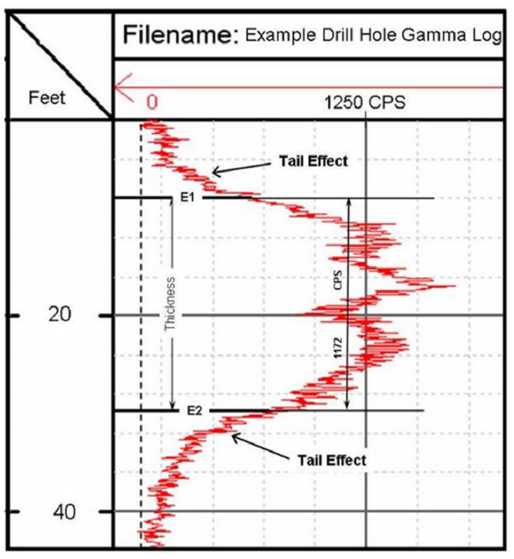
Source: SRK, 2006
Figure 10-1: Example Gamma Log -- Half-Amplitude Method
| FD/AVM/CKH | March 2015 |
| SRK Consulting | |
| NI 43-101 Technical Report on Resources Wate Uranium Breccia Pipe – Northern Arizona, USA. | Page 44 |
| 11 |
Data Verification (Item 12) |
SRK Data verification has been accomplished by the following:
| • | Visual inspection of alteration, rock types, and structure in outcrop and at prospects on VANE’s breccia pipe properties; | |
| • | Location in the field of historical drill sites that are marked with drillhole identification and correspond to location on maps; | |
| • | Observation in the field of more than two times background radiation, as shown by a hand-held scintillometer; | |
| • | Copies of external lab test results (geochemical) that also confirm uranium mineralization in select samples; | |
| • | Examination of gamma logs to verify mineralized intercepts; | |
| • | Examination of replicate gamma logs from a second contract logging company; and | |
| • | Comparison of VANE gamma-log data composite intervals with historically reported composite intervals for the re-logging of WT-5 and WT-7 |
Visual inspection in the field confirms the geology as typical of uranium breccia pipes. Malachite and boxwork iron oxides (limonite and hematite) and casts after former pyrite are visible in some outcrops. Elsewhere, gently inward-dipping stratigraphy toward a depression or semi-circular topographic low area suggests stratigraphic collapse indicative of a breccia pipe. The authors did not directly confirm, visually or through sampling, the uranium mineralization, as identification is often difficult in oxidized and weathered outcrops. However, the analytical results of VANE’s sampling verify uranium mineralization where identified in some prospects. The inward dipping stratigraphy is notable in outcrop at the Wate Pipe.
Also visible in the field are historical drill roads and drill sites. A number of RME’s former drillholes have been located in the field. At the Wate pipe, the drillhole collars were covered with a few inches of dirt and were located by carefully scraping away the top layers of soil cover to define the drillholes.
Historical drill core prior to VANE’s drilling is not available for inspection. Visual inspection confirms the geology as described by VANE. Inward dipping Kaibab Limestone, semi-circular areas of Moenkopi red mudstone internal to Kaibab limestone, brecciated beds, higher than background CPS on the scintillometer, locally copper oxide mineralization, alteration, and iron-oxides along fractures and after former sulfides are visible in outcrop; and all are indicators of breccia pipes, although often subtle or difficult to identify. At this early stage of exploration, there are no data verification issues for the Project. The geological concepts and exploration targets are verifiable in the field.
VANE drilling in 2008 and 2009 has verified the mineralization historically reported and has confirmed high grades for which historical information is not yet available at the Wate pipe. Reentering of historical drillholes at the Wate Pipe and new down-hole surveys have verified the historical drillhole deviations and the traces portrayed on plan maps.
Comparison of historically reported versus VANE re-logged mineralized intervals in WT-5 and WT-7 are shown below in Table 11-1. The 0.5 ft interval data from VANE re-logs using both Century Wireline Services and Geophysical Logging Services were selected to match composite intervals listed in RME reports for the historical holes.
| FD/AVM/CKH | March 2015 |
| SRK Consulting | |
| NI 43-101 Technical Report on Resources Wate Uranium Breccia Pipe – Northern Arizona, USA. | Page 45 |
Table 11-1: Comparison of Historical and VANE re-logs for WT-5 and WT-7
From(ft) |
To (ft) |
Interval |
Grade
(%U3O8) | |
| WT-5 | ||||
| VANE-Century Wireline Services | 1486.0 | 1519.5 | 33.5 | 1.69 |
| VANE-Geophysical Logging Services | 1483.5 | 1517.0 | 33.5 | 1.46 |
| RME-Historical Intercepts reported | 1491.0 | 1524.5 | 33.5 | 1.17 |
| VANE-Century Wireline Services | 1489.5 | 1495.5 | 6.0 | 4.99 |
| VANE-Geophysical Logging Services | 1489.5 | 1495.5 | 6.0 | 3.87 |
| RME-Historical Intercepts reported | 1493.0 | 1499.0 | 6.0 | 4.44 |
| WT-7 | ||||
| VANE-Century Wireline Services | 1243.5 | 1254.5 | 11.0 | 0.38 |
| VANE-Geophysical Logging Services | 1241.0 | 1252.0 | 11.0 | 0.38 |
| RME-Historical Intercepts reported | 1245.0 | 1256.0 | 11.0 | 0.34 |
Source: SRK, 2010
Note: Selected
intervals in Table 14-1 may not exactly match mineralized intervals listed
elsewhere in this report
The comparison shows that VANE re-logs of historical drillhole verify the drillhole survey trace as well as the thickness and grade of mineralization for WT-5 and WT-7.
SRK’s conclusion is that the historical data has been verified for some drillholes at the Wate Pipe, and that VANE’s drilling of new holes provides sufficient new information to validate mineralization where historical information is currently not available. At the Wate Pipe, VANE has verified a portion of the historical drillhole database by re-entering and re-logging the old holes, and has confirmed similar grades in nearby new drillholes, as demonstrated in a comparison of WT-5 with WT-29A in Section 13.11 ( Table 13-8 ). This database provides confidence that the historical data are valid and can be sufficiently replicated with additional confirmation drilling.
SRK is of the opinion that there is sufficient verifiable information to adequately define Inferred mineral resources as stated in section 16 of this report.
| FD/AVM/CKH | March 2015 |
| SRK Consulting | |
| NI 43-101 Technical Report on Resources Wate Uranium Breccia Pipe – Northern Arizona, USA. | Page 46 |
| 12 |
Mineral Processing and Metallurgical Testing (Item 13) |
SRK recommends that the core from drillholes WT-29A, WT-39, and WT-41 be evaluated with preliminary mineralogical, geochemical, and metallurgical testing, to verify the uranium mineralization is amenable to standard processing methods. No mineral processing or metallurgical testing has been completed for this project as of the date of this report. However, core from mineralized intervals has been collected for this purpose.
Historical mined uranium-bearing breccia pipe ores in Arizona were transported by truck to the White Mesa mill in Blanding, Utah, currently owned by Energy Fuels. The processing for Arizona breccia pipe uranium ores was done at the White Mesa mill in Blanding, using conventional uranium milling circuits. The Blanding Mill has continued to process alternative feed sources during the period of low uranium prices, and is now accepting mined uranium ores as feed. Currently, there are no uranium processing options in Arizona, and none are known to be in the planning stages.
| FD/AVM/CKH | March 2015 |
| SRK Consulting | |
| NI 43-101 Technical Report on Resources Wate Uranium Breccia Pipe – Northern Arizona, USA. | Page 47 |
| 13 |
Mineral Resource Estimate (Item 14) |
This section on Mineral Resources relates to historical drilling and more recent drilling conducted by VANE in the period on 2009 to 2011. No drilling has been conducted since 2011. The mineral resources stated in this Section are as of March 22, 2011, the date of the most current drill information, and the mineral resources are still current as of the date of this report.
During 2010 SRK completed an updated resource estimate for the Wate Pipe, using information available at that time. Subsequent to the completion of that resource Vane successfully targeted two new drillholes, WT-39 and WT-41, that intersected higher grade mineralization as predicted by the model; providing at least a conceptual validation of the delineation of the mineralization. During the 2011 update, only the primary resource zone, constituting more than 80% of the resource (Zone 1), was remodeled as discussed below. The resources for Zones 2-4 are those calculated from the 2010 model (previously reported in a NI 43-101 technical report dated November 04, 2010), as the most recent drilling since 2010 did not intersect those Zones..
The mineral resources stated in this section for the Wate Pipe have been classified according to the “CIM Standards on Mineral Resources and Reserves: Definitions and Guidelines” (November 2010). Accordingly, the Resources have been classified as Inferred. There are no Measured or Indicated resources and no mineral reserves are currently established for the Project.
Historically, 21 drillholes defined the mineralization for the Wate Pipe. VANE has cleaned and re-logged two historical holes that verify mineralization, and drilled 13 new holes in the Wate Pipe. In addition, a number of historical holes, located on a cross-section and on a plan map, were digitized for down-hole location and form part of the drillhole geological database; composite assay data for mineralized intercepts in these historical holes was made available to VANE in July/August 2010. As there are no backup geological or gamma logs to verify the reported intercepts, the historical drillholes were used solely for the definition of mineralized shapes; only VANE drillhole eU3O8 grade determinations were used for grade estimation.
| 13.1 |
Drillhole Database |
The drillhole database is composed of 21 historical drillholes and 15 drillholes completed or re-logged by VANE since 2008. The 36 drillholes total 63,303.5 ft. of drilling. VANE’s 15 new and re-logged drillholes total 23,985.5 ft. of drilling. VANE re-opened/re-logged two mineralized holes, WT-5 and WT-7. Selected drillhole information is summarized in Table 16.1. As stated in Section 13 and Table 13-1, VANE drill hole gamma logging has verified the historical drillhole intercepts for WT-5 and WT-7 with very good correlation. It should also be noted that in the re-logs of WT-5 and WT-7 by VANE, the downhole survey data compared favorably with the historic RME survey data which provides confirmation as to the accuracy of the RME downhole survey data.
There was sufficient information from new logs, the historical drillhole cross-section, and a plan map showing the interpreted map of the pipe perimeter at various elevations, to construct a 3D depiction of the pipe shape for the area of mineralization.
Historical drillhole intercepts are available to VANE in the form of drill depth, composite interval (intercepts picks) and interval composite grades. That information became available to VANE in July/August 2010 in RME historical progress reports for the drilling at Wate. Historical gamma-logs from which the interval eU3O8 data were derived are not available to VANE; therefore, for all historical holes except WT-5 and WT-7, the historical drillhole intercepts cannot be verified. SRK considers the historical intercept data partially verified by VANE and thus reasonable to assume that the entire database of historical holes is sufficiently accurate to be used for delineation of the mineralized shapes within which block model construction and grade assignment was accomplished using VANE-only 0.5 ft. eU3O8 data.
The limitation in using all the historical drillhole intercepts for grade assignment comes from the disparity in sample data intervals; 0.5 ft. from VANE data and large composite intervals from historical holes. All VANE holes have 0.5 ft. interval eU3O8 data, and all of the historical holes are composited (intercept) intervals. Some of the holes, such as WT-09A, and WT-13, as highlighted in Table 16-1 have over 50 ft. @ +1.0% eU3O8. These large composite intervals, for which the compositing criteria are not known, offer no insight to the actual grade distribution internal to the composite interval, and they cannot be satisfactorily compared to nearby VANE holes that have 0.5 ft. grades. The side-by-side comparison of historical versus VANE holes is demonstrated in Figure 16.1. It shows the mineralized shape created from all data and the comparison of WT-29 and VANE’s WT-29A. WT-29 has two composite intercepts internal to the mineralized shape, whereas WT-29A has 56 0.5 ft. intervals that range in grade from 0.14% to 4.60% eU3O8. The two holes are about 12 ft. apart, and the compositing in WT-29 to 30.5 ft. @ 0.83% is difficult to relate directly to the variable grade in WT-29A; yet overall, all holes show good continuity of mineralization.
| FD/AVM/CKH | March 2015 |
| SRK Consulting | |
| NI 43-101 Technical Report on Resources Wate Uranium Breccia Pipe – Northern Arizona, USA. | Page 48 |
![]()
Figure 13-1: Cross Section of Historical and VANE drillholes (SRK 2011
In contrast to Figure 13-1, Figure 13-2 shows that locally significant variation can occur in two immediately adjacent drillholes, such as WT-39 with historical hole WT-9A, and even WT-41 and WT-42; in both cases the hole pairs are less than 10 feet apart. This results in difficulty to accurately define the mineralized boundaries, and the interpolated block grades internal to a mineralized shape become a blended grade; a combination of the higher and lower grades. The likely explanation for these close-hole differences in grade is stepping across a mineralization-controlling pipe-boundary fault structure. Such a structure cannot be accurately defined by vertical drilling alone.
| FD/AVM/CKH | March 2015 |
| SRK Consulting | |
| NI 43-101 Technical Report on Resources Wate Uranium Breccia Pipe – Northern Arizona, USA. | Page 49 |
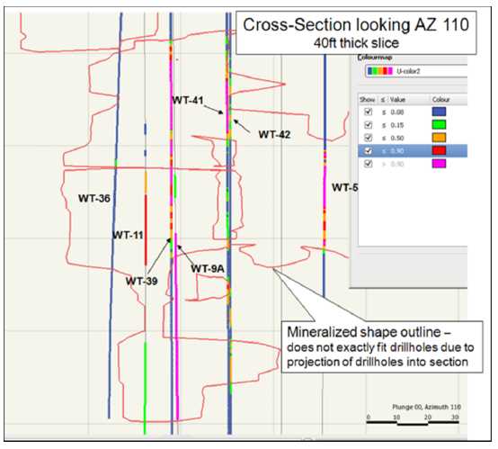
Figure 13-2: Cross Section of Historical and VANE drillholes (SRK 2011)
Table 13-1 is a list of selected reported historical mineralized intervals to demonstrate the quality of the data. It is not a complete list of historical drillhole intercepts.
| FD/AVM/CKH | March 2015 |
| SRK Consulting | |
| NI 43-101 Technical Report on Resources Wate Uranium Breccia Pipe – Northern Arizona, USA. | Page 50 |
Table 13-1: Selected Historical Drillhole Intercepts – Wate Pipe
| Hole_ID | From (ft) | To (ft) | Interval | % U3O8 |
| WT-08 | 1292.5 | 1326.5 | 34 | 0.074 |
| WT-08 | 1455 | 1459.5 | 4.5 | 0.149 |
| WT-08 | 1502 | 1503 | 1 | 0.258 |
| WT-09A | 1294 | 1300.5 | 6.5 | 0.211 |
| WT-09A | 1307 | 1310.5 | 3.5 | 0.11 |
| WT-09A | 1491 | 1498.5 | 7.5 | 0.125 |
| WT-09A | 1510 | 1570.5 | 60.5 | 1.431 |
| WT-10 | 1437.5 | 1441 | 3.5 | 0.141 |
| WT-10 | 1462 | 1489.5 | 27.5 | 0.214 |
| WT-10 | 1490 | 1509 | 19 | 0.297 |
| WT-11 | 1490 | 1497 | 7 | 0.418 |
| WT-11 | 1497.5 | 1520.5 | 23 | 0.53 |
| WT-11 | 1545.5 | 1587.5 | 42 | 0.149 |
| WT-13 | 1428 | 1482 | 54 | 1.172 |
| WT-14 | 1468 | 1490 | 22 | 0.515 |
| WT-15 | 1454 | 1487.5 | 33.5 | 0.772 |
| WT-25 | 1484 | 1507 | 23 | 0.558 |
| WT-25 | 1508.5 | 1536.5 | 28 | 0.576 |
| WT-25 | 1538 | 1573.5 | 35.5 | 0.169 |
| WT-26 | 1460 | 1466 | 6 | 0.494 |
| WT-26 | 1495.5 | 1500.5 | 5 | 0.156 |
| WT-26 | 1503 | 1504.5 | 1.5 | 0.185 |
| WT-28 | 1460 | 1466 | 6 | 0.488 |
| WT-28 | 1495 | 1503 | 8 | 0.111 |
| WT-28 | 1503.5 | 1510 | 6.5 | 0.16 |
| WT-29 | 1310 | 1340.5 | 30.5 | 0.827 |
| WT-29 | 1501 | 1504.5 | 3.5 | 0.047 |
| WT-29 | 1506.5 | 1509 | 2.5 | 0.075 |
| WT-29 | 1509 | 1533.5 | 24.5 | 0.58 |
| WT-30 | 1347 | 1382.5 | 35.5 | 1.94 |
| WT-30 | 1457.5 | 1458.5 | 1 | 0.172 |
| WT-30 | 1496.5 | 1499 | 2.5 | 0.041 |
| WT-30 | 1499 | 1525.5 | 26.5 | 1.343 |
| WT-31 | 1320 | 1343 | 23 | 1.204 |
| WT-31 | 1373.5 | 1379.5 | 6 | 0.029 |
| WT-31 | 1453.5 | 1458 | 4.5 | 0.202 |
Table 13-2 is a tabulation of the VANE drillhole data for which 0.5 ft. eU3O8 data are available, and which was the only data used for grade interpolation and block model grade assignment.
| FD/AVM/CKH | March 2015 |
| SRK Consulting | |
| NI 43-101 Technical Report on Resources Wate Uranium Breccia Pipe – Northern Arizona, USA. | Page 51 |
Table 3-2: Drillhole Database Statistics – VANE Drillholes (SRK, April 2011)
| WT-29A upper |
WT-29A lower |
WT-33 |
WT-34 |
WT-35 (cum) |
WT-37 upper |
WT-37 middle |
WT-37 lower |
WT-39 (un-cut) |
WT-41 |
Wt-42 (cum) |
WT-5 |
WT-7 | |
| Thickness (ft) |
36.0 | 28.0 | 25.5 | 15.0 | 21.5 | 20.0 | 2.5 | 12.5 | 64.5 | 27 | 35.5 | 32.5 | 9.0 |
| Ave Grade (%U3O8) |
0.69 | 1.60 | 0.45 | 0.30 | 0.33 | 0.37 | 0.19 | 1.29 | 1.45** | 1.45 | 0.25 | 1.52 | 0.47 |
| No 0.5 ft interval |
72 | 56 | 51 | 30 | 31 | 40 | 5 | 25 | 129 | 54 | 71 | 65 | 18 |
| No. > 0.5% eU3O8 |
34 | 49 | 22 | 0 | 6 | 10 | 0 | 20 | 101 | 36 | 4 | 45 | 7 |
| High value (% eU3O8) |
2.47 | 4.61 | 0.97 | 0.48 | 0.69 | 1.39 | 0.25 | 3.18 | 18.35* | 2.92 | 1.12 | 4.38 | 1.21 |
| from (ft) | 1318.0 | 1498.5 | 1421.0 | 1269.5 | 1333.5 | 1299.0 | 1328.0 | 1362.5 | 1448 | 1453.5 | 1246 | 1483.5 | 1242.5 |
| to (ft) | 1354.0 | 1526.5 | 1446.5 | 1284.5 | 1370.0 | 1319.0 | 1330.5 | 1375.0 | 1512.5 | 1480.5 | 1599.5 | 1516.0 | 1251.5 |
| GT (Ft-%) | 24.7 | 44.7 | 11.5 | 4.5 | 7.1 | 7.3 | 0.5 | 16.1 | 93.6 | 39.1 | 8.71 | 49.3 | 4.3 |
Note: WT-35 and WT-42 represent
cummulative intercept intervals; WT-5 and WT-7 are re-logs of historical holes
WT-36 , WT-38, and WT-40 did not encounter +0.15% mineralization
* Two 0.5 ft interval at 10.3% and
18.4% in WT-39
** Two 0.5 ft
interval capped at 7.0% in WT-39 -
results in 1.29% average
grade
| FD/AVM/CKH | March 2015 |
| SRK Consulting | |
| NI 43-101 Technical Report on Resources Wate Uranium Breccia Pipe – Northern Arizona, USA. | Page 52 |
| 13.2 |
Assay Data – Population Domain Analysis |
Figure 13-3 below is the cumulative relative frequency distribution diagram for the Wate Pipe raw eU3O8 data. In 2010 using the cumulative frequency distribution diagram (CF plot) as a guide, in conjunction with an examination of the distribution of drillhole data, three “thresholds” were selected. First, a minimum threshold was selected distinguishing lower grade “mineralized” versus non-mineralized material based, subjectively, by choosing an inflection point on the lower grade tail of the CF plot. Second, a threshold was selected above which grades would be considered part of a “higher grade” population, which might require separate grade estimation constraints. Third, an inflection point was selected to identify assays that are to be considered “outliers” to the general distribution and “capped” or set back to a defined threshold. The thresholds identified are tabulated below on Table 13-3 and shown in bold font on the CF plot. An additional intermediate inflection at approximately 0.9, or 1.0% eU3O8, was initially examined in 2010 as well but with the paucity of data, the analysis of this as a separate population was abandoned.
The 2011 SRK interpretation is that the mineralization within the Wate pipe Zone 1 is not uniform; a higher grade area or “domain” (Domain 1) is bounded by lower grade material; this is visually apparent as well as reflected on the distribution diagrams. Alternative thresholds for the capping of higher grade values were examined; the selected process was to apply a cap of 3.2% to all data in all domains prior to compositing for the estimation of grade. The higher grade domain was subsequently re-estimated using a database capped at 4.6% using a “soft boundary” constraint whereby values external to the delineated domain along with values internal to it were applied.

Figure 13-3: Wate Pipe Cumulative Relative Frequency Distribution (SRK 2011)
| FD/AVM/CKH | March 2015 |
| SRK Consulting | |
| NI 43-101 Technical Report on Resources Wate Uranium Breccia Pipe – Northern Arizona, USA. | Page 53 |
Table 13-3: Wate Pipe Zone 1 Grade Population Cutoff Thresholds
| Population | Threshold (eU3O8%) |
| Mineralized | ≥0.17 |
| Domain 0 Cap | ≥3.2 |
| Domain 1 Cap | ≥4.6 |
| 13.3 |
Mineralization Envelopes |
For the purpose of identifying mineralized versus non-mineralized material within the overall pipe structure, drillholes were digitized by VANE personnel from a plan map in a historical RME report with down-hole survey ticks, allowing for a 3D depiction of all the historical drillholes – essentially generating a down-hole survey for each hole. VANE provided SRK with an Excel spread sheet database of combined historical drillhole intercepts and VANE drillhole 0.5 ft. eU3O8 data.
In 2010 SRK created wireframe shapes of mineralization in Leapfrog® software using all drillhole data. The process involved creating 2-D strings around mineralized drillholes on sections. Figure 16-3 demonstrated how 2-D strings were created around mineralized drillholes. A set of 2-D strings were created in space on parallel sections and linked to create a 3-D solid shape, as shown in Figure 13-4 and Figure 13-5.
| FD/AVM/CKH | March 2015 |
| SRK Consulting | |
| NI 43-101 Technical Report on Resources Wate Uranium Breccia Pipe – Northern Arizona, USA. | Page 54 |

Figure 13-4: Cross-Section of Mineralized Drillholes and 2-D strings (SRK 2010)
| FD/AVM/CKH | March 2015 |
| SRK Consulting | |
| NI 43-101 Technical Report on Resources Wate Uranium Breccia Pipe – Northern Arizona, USA. | Page 55 |

Figure 13-5: Oblique View of 2010 Mineralized Shape (SRK 2010)
The mineralized shapes created in Leapfrog were then exported to Datamine® Studio 3 software. In Datamine, the initial Leapfrog 3-D shapes were modified on orthogonal sections to result in a better fit (tighter) to the drillhole data, with extensions to the interpreted pipe boundary where possible. The shape shown in Figure 13-5 was modified to that shown in Figure 13-6, which is the shape (grade shell) used to constrain the 2010 block models and as can be noted from the displays envelopes both mineralized and non-mineralized intercepts. For the 2010 model indicators of “local potential” mineralization were assigned to blocks within the global mineralization wireframes as described in Section 13.9.
For the 2011 update enough intercepts were available to interpret “hard” mineralization boundaries for the primary zone, Zone 1, (which represents over 80% of the resource estimated in 2010.) To accomplish this the grade shell used in 2010 was sliced to form plan view strings (Figure 13-7) which were modified and re-linked to form a much “tighter” representation where all assay values inside the shape are used for grade assignment (Figure 13-8). Zones 2 through 4 remain unchanged since the 2010 update.
| FD/AVM/CKH | March 2015 |
| SRK Consulting | |
| NI 43-101 Technical Report on Resources Wate Uranium Breccia Pipe – Northern Arizona, USA. | Page 56 |

Figure 13-6: Oblique View of 2010 Mineralized Shape (SRK 2010)

Figure 13-7: Plan View delineation (SRK 2011)
| FD/AVM/CKH | March 2015 |
| SRK Consulting | |
| NI 43-101 Technical Report on Resources Wate Uranium Breccia Pipe – Northern Arizona, USA. | Page 57 |
![]()
Figure 13-8: Zone 1 Grade shell (SRK 2011)
| FD/AVM/CKH | March 2015 |
| SRK Consulting | |
| NI 43-101 Technical Report on Resources Wate Uranium Breccia Pipe – Northern Arizona, USA. | Page 58 |
| 13.4 |
Composition |
Subsequent to capping raw assays were down-hole composited into two foot lengths. While the selection of the two foot composite length was somewhat arbitrary, it was intended to reflect the selectivity that might be obtained on the margins of potentially mineable units during underground mining or subsequent radiometric sorting. For Zones 2-4 “Discriminator”, or “indicator”, codes were assigned to composites values based on the grade populations of Table 13‑3 and were used for the modeling of these zones in 2010. For the primary mineralized zone (Zone 1) indicators or discriminators were not used as a “hard boundary” (with 607 internal composites) was constructed for the mineralization; obviating the requirement for mineralized versus non-mineralized discriminators. The Zone 1 mineralization was also spatially differentiated with the delineation of higher and lower grade Domains (as soft boundaries) which eliminated the requirement for a “higher grade” threshold. Table 13-4 summarizes the composite statistics. The Domain databases are identical except for capping thresholds.
Table 13-4: Zone 1 Composite Summary Statistics
| eU3O8% for 2-Foot Composites | |||
| Population | All | Domain 0 | Domain 1 |
| Number Of Values | 28310 | 607 | 607 |
| Maximum Value | 9.7150 | 3.2 | 4.435 |
| Minimum Value | 0.00 | 0.00 | 0.00 |
| Mean | 0.0149 | 0.614 | 0.622 |
| Variance | 0.021 | 0.427 | 0.474 |
| Standard Deviation | 0.1452 | 0.654 | 0.689 |
| Coefficient Of variation | 9.7 | 1.07 | 1.11 |
| 13.5 |
Specific Gravity Measurements (Bulk Density) |
A tonnage factor of 13 ft3/ton was assigned to all material.
| 13.6 |
Block Models |
SRK constructed a block model using the Datamine Studio3® mining software package for the Wate Breccia Pipe. Block sizes are initially 1ft by 1ft in plan and 2ft vertically. The model has the following spatial limits (Table 13-5):
Table 13-5: Wate Pipe Model Limits
| Breccia Pipe Direction |
Model Limits
Minimum(ft) |
Maximum(ft) |
| Easting | 427,400 | 427,700 |
| Northing | 1,830,000 | 1,830,200 |
| Elevation | 4,300 | 4,800 |
| 13.7 |
Mineralization Zones |
Within the Wate Pipe, four more or less vertically separated zones of mineralization have been identified (with additional drilling one or more of these may be combined); for convenience, these were enumerated as zones one through four from bottom to top (note that for previous estimations the zone designations were different). For each of the zones, global mineralized envelopes were constructed to represent the maximum overall global limits of potential mineralization as discussed in 13.3. Figure 13‑9 displays the zones superimposed on the overall breccia pipe wireframe (which was provided to SRK and created from RME plan interpretations by VANE). In some cases, the mineralized shapes extend beyond the pipe wireframe, but significant mineralized drillhole intercepts do as well. SRK is of the opinion that the accuracy of the mineralized zone wireframes is at least that of the overall pipe wireframe; therefore honored wireframes derived from drillholes over the interpreted pipe boundary. Zone codes one through four were assigned to model block positions.
| FD/AVM/CKH | March 2015 |
| SRK Consulting | |
| NI 43-101 Technical Report on Resources Wate Uranium Breccia Pipe – Northern Arizona, USA. | Page 59 |

Figure 13-9: Wate Breccia Pipe and Mineralized Zones (SRK 2011)
| 13.8 |
Dynamic Anisotropy and Search Orientation |
With the extremely limited data set available, variograms and indicator variograms yielded very scattered and generally non-interpretable results. Given the variation of lower and higher grade values, and the lack of closely spaced values, very erratic results were obtained with very high nugget values relative to sills. In particular, no preferential orientations (anisotropies) of the continuity of mineralization could be observed.
The dynamic anisotropy option in Datamine Studio3® allows the anisotropy rotation angles for defining the search volume and variogram models to be defined individually for each cell in the model. The search volume is oriented precisely and follows the trend of the mineralization. The rotation angles are assigned to each cell in the model; it is assumed that the dimensions of the ellipsoid, the lengths of the three axes, remain constant. A point file, where each point has a value for dip and dip direction, was created for each zone wireframe and are intended to represent the preferential “down dip” direction, which varies locally, over the vertical and horizontal extent of the wireframes. Since the three axes of the search volume are orthogonal and only two rotations are used (dip and dip direction) the orientation of all three axes are explicitly defined. The point values are taken from the orientation of the triangular facets that comprise the surface of a wireframes or digital terrain model.
For zones one through four, planes were constructed to represent the overall trend or orientation of mineralization. These are subjective geological interpretations based on the overall geometries of the mineralized shapes, the location of significant mineralized drillhole intercepts within them and presumed behavior such as a “draping” of the mineralization at the contact with the breccia pipe boundaries. These are converted to points each with a unique orientation and can be seen as the “arrows” on Figures13‑10, 13‑12 and 13‑13. Values for dip and dip direction were assigned to model block positions.
| FD/AVM/CKH | March 2015 |
| SRK Consulting | |
| NI 43-101 Technical Report on Resources Wate Uranium Breccia Pipe – Northern Arizona, USA. | Page 60 |

Figure 13-10: Wate Pipe Mineralized Zone 1 and Anisotropy Points (SRK 2011)
| 13.9 |
Mineralization Indicator Assignment, Zones 2-4 |
For the 2010 model (Zones 2-4 were unchanged in 2011) the mineralization envelopes define the maximum overall “broad global limits” of potential mineralization, clearly a pattern of mineralized versus non-mineralized can be observed in the drillholes with significant mineralized intercepts varying from a few to tens of feet in extent. For the purpose of assigning indicators of “local potential” mineralization to blocks within the global mineralization wireframes described in Section 16.7 above, the composite file, described in Section 16.4, was used with indicators of 1 if its composited value exceeded the lower grade population threshold (identified on 3) or 0 otherwise. These 1 and 0 values were then assigned (nearest neighbor) into the deposit model block positions using the dynamic anisotropy orientations described in Section 16.8 above. Large search distances with 2 to 1 anisotropies (search along the orientation is twice that of across) were employed.
| 13.10 |
Domain Assignment, Zone 1 |
Within the overall mineralization a higher grade domain has been identified, possibly the result of remobilization or higher porosity, and a wireframe delineation of the area was constructed as shown in red below on figure 13-11 and 13-12 below.
| FD/AVM/CKH | March 2015 |
| SRK Consulting | |
| NI 43-101 Technical Report on Resources Wate Uranium Breccia Pipe – Northern Arizona, USA. | Page 61 |

Figure 13-11: Wate Pipe and Domains 1(Red) 0 (Green) (SRK 2011)
| FD/AVM/CKH | March 2015 |
| SRK Consulting | |
| NI 43-101 Technical Report on Resources Wate Uranium Breccia Pipe – Northern Arizona, USA. | Page 62 |
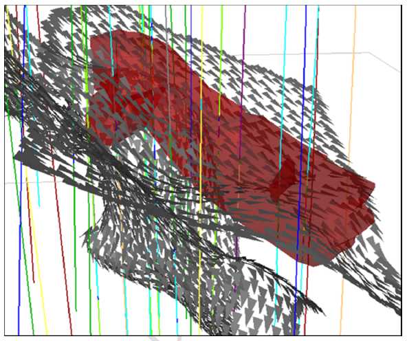
Figure 13-12: Wate Pipe Anisotropy Points and Domain 1 (SRK 2011)
| 13.11 |
Grade Estimation and Resource Classification Criteria |
As noted above the 2011 model update was restricted to the primary resource zone, constituting more than 80% of the resource (Zone 1). The resources for Zones 2-4 are those calculated from the 2010 model and the grade estimation methodology remains that used in 2010.
With the limited sample set available (and erratic variography) an inverse to the distance power of two was chosen to weight grades selected in the search ellipse. The orientation of the search ellipse was controlled by the dynamic anisotropies as discussed in Section 16.8. Table 16‑6 and Table 16‑7 below summarize the interpolation parameters for the Zone 1 Domains.
Table 13-6: Estimation Parameters (Domain 0)
| SVOL | Search Distance (feet) | Minimum Number
Of Composites |
Maximum From
One Drillhole | |||
| CLASS | X | Y | Z | |||
| 1 | Inferred | 100 | 50 | 25 | 3 | 2 |
| 2 | Inferred | 200 | 100 | 50 | 3 | 2 |
| FD/AVM/CKH | March 2015 |
| SRK Consulting | |
| NI 43-101 Technical Report on Resources Wate Uranium Breccia Pipe – Northern Arizona, USA. | Page 63 |
Table 13-7: Estimation Parameters (Domain 1)
| SVOL | Search Distance (feet) | Minimum Number
Of Composites |
Maximum From
One Drillhole | |||
| CLASS | X | Y | Z | |||
| 1 | Inferred | 25 | 12.5 | 6 | 3 | 2 |
| 2 | Inferred | 50 | 25 | 12 | 3 | 2 |
For both Domains, to preserve local grade variation, a search neighborhood strategy with two search ellipse (SVOL) volumes was employed. Only blocks not estimated with the first set of parameters were estimated with a subsequent expanded search. A minimum of three two-foot composites was required, with a maximum of two from any given hole, for estimation with either of the search volumes.
Initially both Domains were assigned grades using a database capped at 3.2 %eU3O8 with the Domain 0 parameters above. Subsequently model blocks, inside of the area delineated as Domain 1, were re-interpolated using a database capped at 4.6 %eU3O8 with the constrained Domain 1 parameters tabulated above. A “soft boundary” has been formed where the influence on values in excess of 3.2 were confined to blocks internal to the Domain while values external to the Domain were also used. This can be seen on Figure 13.13 where the grade transition across the Domains is not abrupt and on Figure 13.14 where all blocks estimated with grades in excess of 3.2 are constrained to Domain 1. Figure 13.15 displays a cross section through the higher grade Domain 1 and Table 13-8 summarizes the intercepts.
Estimation parameters used in 2010 for Zones 2-4 are similar to those tabulated above. For the 0.15% eU3O8 threshold (Indicator 1) a minimum of three two-foot composites was required, with a maximum of two from any given hole, for estimation with either of the search volumes. For the 2.9% eU3O8 threshold (Indicator 3) a minimum of one two-foot composites was required, with a constrained search distance. Hard boundary zonal controls were employed in that blocks coded with an indicator of 3 were assigned grades using only indicator 3 composites to form the higher grade zone. Indicator 3 blocks not assigned grades during this process and blocks coded indicator 1 were subsequently interpolated using only composites coded as indicator 1.
For future models, alternative methods could be adopted. With considerably more data, multiple indicator kriging or conditional simulation methodologies could be examined. The grades of eU3O8% were estimated using the dynamic search orientation as described above, with a two-to-one anisotropy (search along primary orientations was twice that across).
| FD/AVM/CKH | March 2015 |
| SRK Consulting | |
| NI 43-101 Technical Report on Resources Wate Uranium Breccia Pipe – Northern Arizona, USA. | Page 64 |

Figure 13-13: Wate Pipe Estimated Blocks and Anisotropy Points (SRK 2011)
| FD/AVM/CKH | March 2015 |
| SRK Consulting | |
| NI 43-101 Technical Report on Resources Wate Uranium Breccia Pipe – Northern Arizona, USA. | Page 65 |
![]()
Figure 13-14: Wate Pipe Estimated Blocks and Domain 1 Shell (SRK 2011)
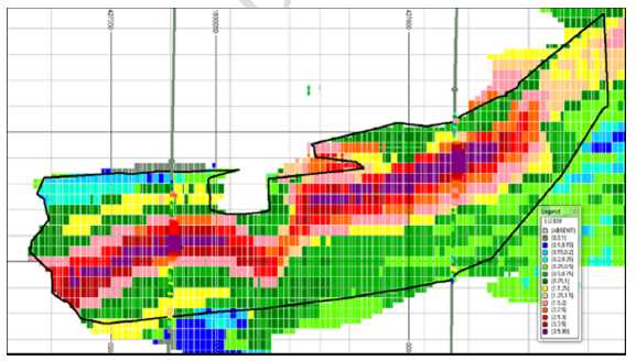
Note: WT-29A on left and WT-05 on right in Figure 16.15 above; holes are approximately 54ft apart; cross-sectional view looking North.
Figure 13-15: Wate Pipe Estimated Blocks, Drillholes WT-05 & WT-29A (SRK 2011)
| FD/AVM/CKH | March 2015 |
| SRK Consulting | |
| NI 43-101 Technical Report on Resources Wate Uranium Breccia Pipe – Northern Arizona, USA. | Page 66 |
Table 13-8: Contiguous 0.5ft Higher-Grade intercepts WT-05 & WT-29A
| WT-05 13.5' eU3O8% (0.5 ft intervals) | |||||||||||||
| 3.13 top |
2.32 | 3.13 | 3.13 | 3.50 | 3.98 | 4.00 | 4.00 | 4.00 | 4.00 | 4.00 | 4.00 | 3.78 | 3.47 |
| 3.03 | 2.67 | 2.47 | 2.43 | 2.02 | 1.74 | 1.91 | 2.20 | 2.21 | 1.97 | 1.98 | 1.66 | 1.07 btm |
|
| WT-29A 12' eU3O8% (0.5 ft intervals) | |||||||||||||
| 0.91 top |
1.47 | 0.91 | 0.99 | 1.94 | 2.62 | 2.99 | 2.93 | 2.89 | 2.87 | 2.98 | 3.66 | 3.57 | 3.67 |
| 4.00 | 4.00 | 3.88 | 3.10 | 2.69 | 2.47 | 2.10 | 1.85 | 1.44 | 1.14 btm |
||||
| 13.12 |
Block Model Validation & Mineral Resource Sensitivity |
The block model was validated visually through a comparison of estimated block grades and those of the original composite file. The comparison is favorable as is a comparison against basic average statistics. As noted, only limited intercepts are available for any comparative analysis on a zone-by-zone basis.
| 13.13 | Resource Statement |
Table 13-9 lists the resources estimated for each zone and the total for all zones at a cutoff of 0.15% eU3O8. All resources are classified by CIM definitions. The cutoff grade of 0.15% eU3O8 is based on a statistical break (Figure 13-3) from essentially non-mineralized to the major population of mineralization (> 0.15%); and the simple estimate that 0.15% equates to 3 pounds U3O8 per ton, and at a $38/pound uranium price, 0.15% eU3O8 would have an in-place value of $114 per ton. That value has a reasonable potential for economic extraction by underground mining methods; no further work was done to determine a true mining cutoff grade at this early stage of the project.
Table 13-9: Inferred Resource by Zone & Total
| Wate Breccia Pipe Inferred Resource | |||||
| 0.15% eU3O8 | |||||
| Cutoff* | |||||
| Zone | Cutoff | U3O8% | Tons (000) | lb-U3O8 (000) | |
| 1 | 0.15 | 0.84 | 58 | 971 | |
| 2 | 0.15 | 0.61 | 11 | 130 | |
| 3 | 0.15 | 0.31 | 2 | 10 | |
| 4 | 0.15 | 0.58 | 1 | 7 | |
| 0.79 | 71 | 1,118 | |||
* Note: Inferred Uranium resources refers to global in-place CIM definitions of resources to which a mine design has not yet been applied; although the above stated resources meet the definition of having the “potential for economic extraction” at the cutoff provided.
| FD/AVM/CKH | March 2015 |
| SRK Consulting | |
| NI 43-101 Technical Report on Resources Wate Uranium Breccia Pipe – Northern Arizona, USA. | Page 67 |
| 13.14 |
Sensitivity of the Resource Model |
As a check on the model, the following analysis was performed:
| • | VANE drillhole data were composited to single intercepts within the wireframe shapes; | |
| • | All drillhole data assay intervals (including historical intercepts) were then used in the block model grade estimation; and | |
| • | The result is a block model that replicates a “polygonal” or nearest-neighbor resource with one composite for each mineralized horizon in each hole | |
The tonnage and grade generated are not considered a reportable resource estimate for two reasons:
| • |
There is very minimal discrimination of grade because of the long intercept intervals, particularly in Zone 1 – and this is not acceptable to SRK as industry standard procedure; and | |
| • |
There is no back-up information for the historical drillholes to allow verification of that data; therefore the data are not sufficient for reporting of resources. |
While the numbers generated by this method are not reportable as a resource, it allows for use of all the drillhole data on the same basis to determine an approximation of the tons and grade that might result if all the data were used; and thus, a check on the method used for reporting resources. The result presents a check that a resource approximating 1.0 million pounds U3O8 is achievable, as shown in Table 13-10.
Table 13-10: Mineralization Inventory Analysis Using all Drillhole Data as Long-interval composites
| Wate Breccia Pipe Mineralization – Check Analysis | |||||
| 0.15% eU3O8 Cutoff – All drillholes used as composite data* | |||||
| Zone | Cutoff | U3O8% | Tons (000) | lb-U3O8 (000) | |
| 1 | 0.15 | 0.64 | 75 | 972 | |
| 2 | 0.15 | 1.10 | 11 | 239 | |
| 3 | 0.15 | 0.19 | 6 | 22 | |
| 4 | 0.15 | 0.31 | 1 | 7 | |
| 0.66 | 93 | 1,241 | |||
*Note: SRK does not consider the values stated as a reportable resource by CIM or any other standard for reporting mineral resources.
| 13.15 | Conclusions and Recommendations |
In SRK’s opinion, to upgrade any portion of the resource from Inferred to Indicated classification, will require additional eU3O8% assay information, either as new drilling or by securing and verifying the historical drilling information, or a combination of both. There is currently insufficient density of drilling information with assay data to determine the optimal spacing of drillhole intercepts that will support an Indicated classification.
The average resource grades of the current resource and the historically reported numbers are similar. This provides a level of confidence, that upon Energy Fuels obtaining additional drilling information, it is reasonable to expect that the historical resource of 1.1 million pounds or more is achievable.
SRK notes that there are current resources located outside the interpreted breccia pipe boundary. SRK considers the pipe boundary to be approximate, and so has honored the drill data rather than truncate the resource model wireframe shapes to the pipe boundary, as SRK considers the accuracy of the wireframes to be at least as good as the pipe boundary. There are also isolated drillhole intercepts internal to the pipe that have not been included in the block model. Therefore, SRK considers the resource model to be neither conservative nor optimistic with respect to modeled data.
| FD/AVM/CKH | March 2015 |
| SRK Consulting | |
| NI 43-101 Technical Report on Resources Wate Uranium Breccia Pipe – Northern Arizona, USA. | Page 68 |
SRK notes that the mineralization modeled are largely bodies located internal to the pipe boundary. Historical mine production experience indicates that these breccia pipe deposits typically have mineralization located on the perimeter of the pipes as well, an annular ring mineralization. The RME historical reports and resources modeled the mineralization in this manner. The vertically oriented perimeter mineralization is very difficult to define with vertical drillholes and is best defined by fan drilling off an access shaft developed outside the breccia pipe. SRK has not modeled perimeter mineralization extending vertically on the walls of the breccia pipe, as RME did, as there is insufficient drilling information there to do so. If this mineralization can be sufficiently defined for the Wate Pipe, it offers an upside resource potential. That potential can be defined from drilling off an exploration shaft.
| FD/AVM/CKH | March 2015 |
| SRK Consulting | |
| NI 43-101 Technical Report on Resources Wate Uranium Breccia Pipe – Northern Arizona, USA. | Page 69 |
| 14 |
Items 15 through 22 |
Item 15 (Mineral Reserve Estimate) is not applicable to this technical report on mineral resources. There are no mineral reserve estimated for the Wate Pipe.
Item 16 (Mining Methods) and Item 17 (Recovery Methods) are not applicable to this technical report on mineral resources.
Item 18 (Project Infrastructure) is not applicable to this technical report on mineral resources other; basic information is provided in Section 3.5
Item 19 (Market Studies and Contracts) is not applicable to this technical report on mineral resources
Item 20 (Environmental Studies, Permitting and Social and Community Impact) is not applicable to this technical report on mineral resources). See Section 16 (Other Relevant Data and Information) for basic information.
Item 21 (Capital and Operating Costs), and Item 22 (Economic Analysis) are not applicable to this technical report on mineral resources
| FD/AVM/CKH | March 2015 |
| SRK Consulting | |
| NI 43-101 Technical Report on Resources Wate Uranium Breccia Pipe – Northern Arizona, USA. | Page 70 |
| 15 |
Adjacent Properties (Item 23) |
There are no immediately adjacent mineral properties that have bearing upon the Wate Project. However, there is another uranium-bearing breccia pipe located less than 10 miles to the southeast of the Wate Pipe. While this Pipe, named Tank 4 ½, has mineralized intercepts, a resource is not yet defined. The Tank 4 ½ Pipe may provide some infrastructure synergies with Wate, should this project advance to resource status with further drilling.
In addition, there are other uranium mineralized breccia pipes in the immediate area, less than 20 miles distant from the Wate Pipe, including the SBF Pipe, Rose Pipe, and the Sage Pipe; any of which might have possible future bearing on project development scenarios for the Wate Pipe.
| FD/AVM/CKH | March 2015 |
| SRK Consulting | |
| NI 43-101 Technical Report on Resources Wate Uranium Breccia Pipe – Northern Arizona, USA. | Page 71 |
| 16 |
Other Relevant Data and Information (Item 24) |
During 2008, exploration activities in the National Forest south of the Grand Canyon National Park came under scrutiny by various anti-nuclear and anti-mining environmental activist groups. Their efforts were against the U.S. Forest Service (USFS) with regard to Plans of Operation for exploration drilling; suggesting the USFS did not take into account potential environmental damage that could occur as a result of exploration drilling for uranium on National Forest lands near the Grand Canyon National Park. The environmental special interest groups, and some local politicians, were annoyed with the Finding of No Significant Impact (FONSI), as determined by the USFS relating to planned drilling programs. A court case ensued, and the result is that the USFS is now requiring an Environmental Impact Statement (EIS) be done prior to drilling rather than an Environmental Assessment (EA). Some local politicians had taken up the cause and had proposed a ban on uranium exploration and mining within federal lands adjacent to Grand Canyon National Park. On July 21, 2009, the Secretary of Interior issued a 2-year Segregation Order and proposed a 20-year withdrawal of approximately 1 M acres of federal lands from mineral entry under the Mining Act of 1872, consisting of BLM lands north of the Grand Canyon and USFS lands south of the Grand Canyon. A regional EIS was initiated to study the potential impacts of mining and the Draft EIS was released in February 2011, with the public comment period ending on May 4, 2011. The decision to withdraw the lands from mineral entry for 20 years was issued by a Us Department of Interior Record of Decision (ROD) on January 9, 2012.. The ROD forced a halt to the drilling of exploration targets in the National Forest (U.S Department of Interior, Jan. 2012). The 20-year withdrawal of activities for uranium on Forest Service lands adjacent to the Grand Canyon National Park is still in effect.
This withdrawal has no effect on private or State lands in the region, and no effect on Energy Fuel’s ability to continue working on the Wate Pipe, which is on Arizona State lands, well outside of National Forest lands.
As briefly discuss in Section 3.3, Subsequent to the cessation of drilling activities in 2011, a Mineral Development Report was completed by VANE and submitted to the Arizona State Land Department, to aid in the process of conversion of the Mineral Prospecting Permit to a Mineral Lease. The MDR was filed on November 19, 2012, and following public comment was revised on October 27, 20014. The process to convert to a Mineral Lease is well advanced, and in the final stages of State approval (pers. Comm., K.Hefton, 2015).
The MDR is a comprehensive report that examines the potential for economic development, in order for the State to issue a Mineral Lease and assign a royalty rate. The MDR is, in the authors’ opinion, a document similar in scope and content to a Preliminary Economic Assessment (PEA). While not a PEA NI 43-101 Technical Report, it addresses all the typical Sections in this technical report on resources, and in addition incudes discussion on the following topics (Wate Mining Company LLC, 2012):
| • | Economic Feasibility | ||
| - | Market Analysis | ||
| - | Costs and Operational Economic Parameters | ||
| - | State Trust Revenues | ||
| • | Environmental Assessment, which includes: | ||
| - | Soils, | ||
| - | Drainage and Erosion | ||
| - | Water Resources, | ||
| - | Biology | ||
| - | Cultural Resources | ||
| - | Hazardous materials | ||
| - | Wastes | ||
| FD/AVM/CKH | March 2015 |
| SRK Consulting | |
| NI 43-101 Technical Report on Resources Wate Uranium Breccia Pipe – Northern Arizona, USA. | Page 72 |
| - | Air Quality | ||
| - | Visual and Noise Impacts | ||
| - | Socio-Economic Impacts | ||
| • | Mine Operations Plan, which includes: | ||
| - | Site development | ||
| - | Mining | ||
| - | Processing | ||
| - | Infrastructure | ||
| - | Safety | ||
| • | Reclamation and Closure Plan | ||
While the intent of the MDR is to provide a potential mining and processing scenario to the State for their purposes of determining a Mining Lease royalty rate; many of the inputs and discussion are applicable to a PEA. SRK’s understanding is the MDR had received comment and feedback from the Arizona State Land Department, was revised by VANE in 2014, and has been accepted by the State as part of the Process of final approval of the Mineral Lease (approval pending). The MDR provides additional Project information beyond the scope of this technical report on resources.
| FD/AVM/CKH | March 2015 |
| SRK Consulting | |
| NI 43-101 Technical Report on Resources Wate Uranium Breccia Pipe – Northern Arizona, USA. | Page 73 |
| 17 |
Interpretation and Conclusion (Item 25) |
The Wate Uranium Breccia Pipe has been historically explored to the point of resource estimation and planned project development. Recent drilling confirmation by VANE has confirmed historically defined high grades in excess of 1.0% eU3O8, and has provided sufficient drilling information to estimate current resources compliant with the CIM classification of “Inferred” resources.
The Wate Pipe is an exploration target for potentially underground-mineable high-grade uranium mineralization (greater than 0.5% U3O8). The Wate Pipe has current estimated Inferred resources by CIM definitions of 71,000 tons grading 0.79% eU3O8 for 1,118,000 contained pounds eU3O8. This resource is based on only partial confirmatory data with respect to historical drilling and resource estimates, and is therefore considered by SRK to be a conservative estimate of the total uranium mineralization in the pipe. The Wate Pipe is a high-grade uranium deposit that justifies further drilling and pre-development work. The project will have all the inherent opportunity and risk of similar mid-stage exploration properties, as defined in the sections below.
The Project represents an attractive mid-stage exploration property with current estimated resources established, and the potential to increase the total resource tons and contained pounds. Energy Fuels has reached an interim goal of achieving a resource estimate of +1.0 million contained pounds, which Energy Fuels considers a minimum requirement to justify an exploration shaft for fan drilling to sufficiently define the mineralization for mine planning purposes. Having reached that goal, Energy Fuel’s preference is to advance the property by underground exploration.
| 17.1 |
Categories of Opportunity and Risk |
| 17.1.1 |
Resources |
The major opportunity at the Project is to define additional uranium grades and intersections in the Wate Pipe, to fully explore the extent of the deposit, and thus potentially add to the current resource. The potential for vertically oriented perimeter mineralization exists, which represents an up-side exploration potential best defined by fan drilling from an exploration shaft.
| 17.1.2 |
Commodity Price Fluctuation |
|
Uranium spot market prices have come off the record highs near $100/lb U3O8 of several years ago, yet remain in the $40/lb range. This represents both an opportunity and a project risk, since prices could fluctuate significantly. However, the relatively high grade of the exploration target suggests that a uranium-bearing breccia pipe with grades in excess of 0.50% U3O8 would be an attractive exploration target even at $40/lb. | |
| 17.1.3 |
Infrastructure |
|
The area has well-developed infrastructure, with easy access by paved roads, available electricity, labor, and equipment, and therefore offers few impediments to the opportunity for potential project development. However, water is a precious commodity and generally occurs at >3,000 ft depths. Well drillers in the vicinity are experienced at completing successful water wells to this depth, and this risk is therefore possible to mitigate. | |
| 17.1.4 |
Development Decision |
|
The relatively small deposit size and the depth suggests that a point will be reached where it is more attractive to sink a shaft and explore the deposit with underground drilling, than to continue drilling from surface. This is a purely business financial risk decision point: whether to drill for maximum resource definition from surface, or to continue exploration toward resource/reserve development from underground. Having reached the 1.0 million pound resource threshold, a next logical decision for Energy Fuels is to sink an exploration shaft and continue to define the mineralization through drift access and fan drilling. |
| FD/AVM/CKH | March 2015 |
| SRK Consulting | |
| NI 43-101 Technical Report on Resources Wate Uranium Breccia Pipe – Northern Arizona, USA. | Page 74 |
| 17.1.5 |
Metallurgical Characteristics |
|
Metallurgical risk factors are cost related. The uranium mining industry is experienced with mining and milling these types of ore deposits, and the current price of uranium is conducive to production. Although there is no metallurgical information yet available, there is nothing unusual anticipated with the uranium mineralization at Wate. Any potential development of Wate would likely require shipment of ore to the existing White Mesa mill in Blanding, Utah, | |
| 17.1.6 |
Environmental/Socio-Economic Considerations |
Environmental issues are always a risk factor in project development. The risks can usually be mitigated by proactively defining the risks and engaging the local populace and government administrators and regulators. The advantages to uranium breccia pipe mining in Arizona are the recent history of uranium mining activity and the small surface area of potential disturbance. In addition, none of the historical Arizona breccia pipe mines have radioactive mill tailings as a reclamation issue, as all ores were trucked to the mills in Utah. After they were reclaimed in the late 1980s, the former Hack Canyon, Pigeon, and Hermit mines of Energy Fuels located north of the Grand Canyon are nearly indistinguishable from the surrounding land.
The current withdrawal of 1M acres of federal lands in the region places further uncertainty on projects on Forest Service lands; however, this withdrawal does not affect any activity on Arizona State Land such as the Wate Pipe.
Mine development on Arizona State lands would be beneficial economically to Arizona’s state budgetary difficulties and has been viewed in a positive light by the Arizona governmental agencies, which is a positive aspect of the project.
SRK considers the upside opportunities to justify continued exploration activities at the Wate Pipe. In SRK’s opinion, the risks are operational and commodity price driven, and all but the commodity price can be quantified and mitigated as the project moves forward.
| FD/AVM/CKH | March 2015 |
| SRK Consulting | |
| NI 43-101 Technical Report on Resources Wate Uranium Breccia Pipe – Northern Arizona, USA. | Page 75 |
| 18 |
Recommendations (Item 26) |
To advance the Project, SRK recommends two avenues for Energy Fuels to acquire additional drilling information for the Wate Pipe:
| • | If possible, secure the historical drill data for the Project; | |
| • | Conduct additional drilling at the Wate Pipe to increase the confidence and perhaps the classification of the current resource. |
SRK recommends a completion of the acquisition of all historical project data from Taiwan Power if financially acceptable terms can be agreed. That historical database will provide sufficient additional information to allow for updating of the 3-D geological model and achieve an increased confidence in the resource estimate. VANE had attempted and nearly exhausted the possibility of securing that back-up historical data. Therefore, the primary recommendation is further confirmation drilling.
SRK recommends Energy Fuels conduct in-fill drilling to demonstrate sufficient continuity to mineralization, and to hopefully increase the confidence classification of the resource. At this point in time it may be more advantageous, technically and from a cost perspective, to conduct further resource definition drilling from an exploration shaft.
SRK does not consider it feasible to define resources to an Indicated or Measured classification without close-spaced underground drilling, as fan drilling from several different levels of an exploration shaft.
A program to develop an exploration shaft and underground resource definition drilling may be justified by the +1.0 million pound Inferred resource at the Wate Pipe; however, a scoping study will determine that in greater detail.
As the cost to develop an exploration shaft is substantial, SRK recommends the next step in the program should be a scoping study to determine the economic potential of the project, as a Phase I program. A Phase II program would include the exploration shaft, extensive underground resource definition drilling, and a pre-feasibility study. The recommended programs and budgets are presented below.
| 18.1 |
Proposed Scoping Study – Phase I |
A Phase I program will consist of a scoping study to determine the economic viability of the current Inferred resource, by developing a mine plan and costing the conceptual mining, processing, and infrastructure for development of the Wate Pipe mineralization. The objective is to verify that a 1.0M pound resource is sufficient to develop at break-even or better economics.
The current resource model would be used for development of a conceptual mine plan with shaft access. Mine development capital and operating costs would be estimated. Processing options would be conceptually reviewed and costs estimated accordingly. Surface facilities and other infrastructure costs would be estimated as well. A technical economic model will be produced to determine the potential economic viability of the project.
Phase I-Scoping Study:
| Scoping Study Report (Preliminary Economic Assessment NI 43-101) | $200,000 |
The estimated time to complete a scoping study is approximately 4 to 6 months.
| 18.2 |
Phase II |
Contingent upon positive economics in the Scoping Study, a Phase II program would include the cost to develop an exploration shaft, conduct extensive underground resource definition drilling, collect a sufficient sample volume for a comprehensive metallurgical test program to verify the metallurgical tests currently being conducted, and conduct a pre-feasibility level study.
| FD/AVM/CKH | March 2015 |
| SRK Consulting | |
| NI 43-101 Technical Report on Resources Wate Uranium Breccia Pipe – Northern Arizona, USA. | Page 76 |
| Construction of an exploration shaft to 1500 feet @ $10,000/ft | $15,000,000 | |
| Development of 3 sub-levels and drill stations for fan drilling | $ 1,000,000 | |
| Underground Core drilling, 8,000 feet @ $100/ft | $ 800,000 | |
| Surface infrastructure for Shaft | $10,000.000 | |
| Pre-Feasibility engineering study and contingency | $ 1,000,000 | |
| Sub-Total Phase II | $27,800,000 |
The estimated time and cost for Phase II work is approximately at 18 to 24 months and US$27.8 million.
| FD/AVM/CKH | March 2015 |
| SRK Consulting | |
| NI 43-101 Technical Report on Resources Wate Uranium Breccia Pipe – Northern Arizona, USA. | Page 77 |
| 19 |
References (Item 27) |
Anonymous, 1991. Evaluation of RME Partners L.P. Wate Uranium Project; unpublished inter-company report by Rocky Mountain Energy, 8p., 10figures.
Beus, S.S., 1989, Devonian and Mississippian geology of Arizona, in Jenney, J.P., and Reynolds, S.J., Geologic evolution of Arizona: Tucson, Arizona Geological Society Digest 17, p. 287-311.
Blakey, R.C., 1989, Triassic and Jurassic geology of the southern Colorado Plateau, , in Jenney, J.P., and Reynolds, S.J., Geologic evolution of Arizona: Tucson, Arizona Geological Society Digest 17, p.369-396.
Blakey, R.C., and Knepp, Rex, 1989, Pennsylvanian and Permian geology of Arizona, in Jenney, J.P., and Reynolds, S.J., Geologic evolution of Arizona: Tucson, Arizona Geological Society Digest 17, p. 313-327.
Cheevers, C.W., and Rawson, R.R., 1979, Facies analysis of the Kaibab Formation in northern Arizona, southern Utah and southern Nevada, in Four Corners Geological Society Guidebook, 9th field Conference, Permianland, p. 105-113.
Chenoweth, W.L., 1986, The Orphan Lode mine, Grand Canyon Arizona, a case history of a mineralized collapse breccia pipe: U.S. Geological Survey Open-File Report 86-510, 126 p.
Cooper, W.C., 1986, Uranium production, in Bever, M.B., ed., Encyclopedia of Materials Science Engineering: Oxford, England, Pergamon Press, v. 7, p. 5215-5218.
Davis, L. and Groom, R., 2008, Preliminary reports on VTEM geophysical data: PetRos EiKon Inc., severa preliminary PowerPoint slide presentation print-outs of geophysical interpretive data for the Miller, Otto, SBF, and Red Dike breccia pipes.;
Energy Fuels Inc., February 17, 2015, Press Release, Energy Fuels Acquires 50% Interest in the High-Grade Wate Uranium Project in Arizona, 3 pages.
Finch, W.I., 1992, Descriptive model of solution-collapse breccia pipe uranium deposits, in Bliss, J.D., ed., Developments in mineral deposit modeling: U.S. Geological Survey Bulletin 2004, p. 33-35.
Flanigan, V.J., Mohr, P.J., Tippens, C., and Senterfit, R.M., 1986, Electrical character of collapse breccia pipes on the Coconino Plateau, northern Arizona: U.S. Geological Survey Open-File Report 86-521, 50 p.
Gornitz, V., Wenrich, K.J., Sutphin, H.B., and Vidale-Buden, R., 1988, Origin of the Orphan mine breccia pipe uranium deposit, Grand Canyon, Arizona, in Vassiliou, A.H., Hausen, D.M., and Carson, D.J., eds., Process mineralogy VII – As applied to separation technology: Warrendale, Penn., The Metallurgical Society, p. 281-301.
Halmbacher, Gerald P., May 26, 1998, An Evaluation of the Wate Breccia Pipe Uranium Deposit (Wate Project) and An Appraisal of Arizona State Mineral Lease 11-52290, prepared for the Arizona State Land Department, by Headquarters West, Ltd., 26 p., 9 exhibits.
Hefton, Kris, March 2, 2015, Personal communication regarding the status of Project activities at the Wate Pipe
Krewedl, D.A., and Carisey, JC., 1986, Contributions to the geology of uranium mineralized breccia pipes in northern Arizona: Arizona Geological Society Digest, volume 16, p. 179-186.
Ludwig, K.R., Rasmussen, J.D., and Simmons, K.R., 1986, Age of uranium ores in collapse-breccia pipes in the Grand Canyon area, northern Arizona (abstract): Geological Society of America Abstracts with Programs, v. 18, no. 5, p. 392.
Ludwig, K.R., and Simmons, K.R., 1992, U-Pb dating of uranium deposits in collapse breccia pipes of the Grand Canyon region: Economic Geology, v. 87, p. 1747-1765.
| FD/AVM/CKH | March 2015 |
| SRK Consulting | |
| NI 43-101 Technical Report on Resources Wate Uranium Breccia Pipe – Northern Arizona, USA. | Page 78 |
McKee, E.D., 1969, Paleozoic rocks of the Grand Canyon: Four Corners Geological Society, Geology and Natural History of the Fifth Field Conference, Powell Centennial River Expedition, p. 78-90.
U.S. Department of Interior, January 9, 2012, Record of Decision, Northern Arizona Withdrawal, Mohave and Coconino Counties, Arizona, 24 pages
Van Gosen, B.S., and Wenrich, K.J., 1989, Ground magnetometer surveys over known and suspected breccia pipes on the Coconino Plateau, northwestern Arizona: U.S. Geological Survey Bulletin 1683-C, 31 p.
Vane Minerals (US) LLC, February 23, 2011, Operating Agreement for Wate Mining Company LLC between Vane Mineral (US) LLC and Uranium One Exploration U.S.A. Inc., 53 pages; and 3 Amendments.
Vane Minerals (US) LLC, May 12, 2011, Updated NI 42-101 Technical Report on Resources, Wate Uranium Breccia Pipe, Northern Arizona, prepared by SRK Consulting, 105 pages.
Verbeek, E.R., Grout, M.A., and Van Gosen, B.S., 1988, Structural evolution of a Grand Canyon breccia pipe –The Ridenour copper-vanadium-uranium mine, Hualapai Indian Reservation, Coconino County, Arizona: U.S. Geological Survey Open-File Report 88-006, 75 p.
Wate Mining Company LLC, November 19, 2012, revised October 27, 2014; Mineral Development Report, Mineral Lease Application 11-116806, for Minerals Section Natural Resources Division, Arizona State Land Department, prepared by Vane Minerals (US) LLC, Uranium One Exploration U.S.A. Inc.
Wenrich, K.J., 1985, Mineralization of breccia pipes in northern Arizona: Economic Geology, v. 80, p. 1722-1735.
Wenrich, K.J., 1986, Geochemical exploration for mineralized breccia pipes in northern Arizona, U.S.A.: Applied Geochemistry, v. 1, no. 4, p. 469-485.
Wenrich, K.J., and Sutphin, H.B., 1988, Recognition of breccia pipes in northern Arizona: Arizona Bureau of Geology and Mineral Technology, Fieldnotes, v. 18, no. 1, p. 1-5, 11.
Wenrich, K.J., and Sutphin, H.B., 1989, Lithotectonic setting necessary for formation of a uranium-rich, solution-collapse breccia-pipe province, Grand Canyon region, Arizona: U.S. Geological Survey, Open-File Report 89-0173, 33 p.
Wenrich, K.J., Chenoweth, W.L., Finch, W.I., and Scarborough, R.B., 1989, Uranium in Arizona, in Jenney, J.P., and Reynolds, S.J., Geologic evolution of Arizona: Tucson, Arizona Geological Society Digest 17, p. 759-794.
Wenrich, K.J., Verbeek, E.R., Sutphin, H.B., Modreski, P.J., Van Gosen, B.S., and Detra, D.E., 1990, Geology, geochemistry, and mineralogy of the Ridenour mine breccia pipe, Arizona: U.S. Geological Survey Open-File Report 90-0504, 66 p.
Wenrich, K.J., Van Gosen, B.S., and Finch, W.I., 1995, Solution-Collapse Breccia Pipe U Deposits, Model 32e (Finch, 1992).
| FD/AVM/CKH | March 2015 |
| SRK Consulting | |
| NI 43-101 Technical Report on Resources Wate Uranium Breccia Pipe – Northern Arizona, USA. | Page 79 |
| 20 |
Glossary (Item 27) |
| Assay: | The chemical analysis of mineral samples to determine the metal content. |
| Background Radiation | That portion of the radiometric total count reading (CPS or counts per second) that are |
| attributable to non-recoverable uranium, potassium and thorium radiation on gamma | |
| logs | |
| Concentrate: | A metal-rich product resulting from a mineral enrichment process such as gravity |
| concentration or flotation, in which most of the desired mineral has been separated from | |
| the waste material in the ore. | |
| Crushing: | Initial process of reducing ore particle size to render it more amenable for further |
| processing. | |
| Dilution: | Waste, which is unavoidably mined with ore. |
| Dip: | Angle of inclination of a geological feature/rock from the horizontal. |
| Fault: | The surface of a fracture along which movement has occurred. |
| Footwall: | The underlying side of an orebody or stope. |
| Gangue: | Non-valuable components of the ore. |
| Grade: | The measure of concentration of gold within mineralized rock. |
| Hanging wall: | The overlying side of an orebody or slope. |
| Lithological: | Geological description pertaining to different rock types. |
| Milling: | A general term used to describe the process in which the ore is crushed and ground |
| and subjected to physical or chemical treatment to extract the valuable metals to a | |
| concentrate or finished product. | |
| Mineral/Mining Lease: | A lease area for which mineral rights are held. |
| Radiation | Or radioactivity; meaning the emissions of alpha, beta, and gamma rays from naturally |
| occurring minerals and rocks. | |
| Scintillometer | A hand-held instrument or down-hole probe that detects radiation as counts per second |
| (CPS) | |
| Sedimentary: | Pertaining to rocks formed by the accumulation of sediments, formed by the erosion of |
| other rocks. | |
| Spectrometer | An instrument that measures CPS radioactivity and differentiates the total CPS spectral |
| radiation emissions into that derived from potassium (K), uranium (U), and thorium (Th), | |
| the most commonly occurring radioactive elements found in rocks and minerals. | |
| Stratigraphy: | The study of stratified rocks in terms of time and space. |
| Strike: | Direction of line formed by the intersection of strata surfaces with the horizontal plane, |
| always perpendicular to the dip direction. | |
| Sulfide: | A sulfur-bearing mineral. |
| Tailings: | Finely ground waste rock from which valuable minerals or metals have been extracted. |
| Total Count | Total CPS from all radioactive sources, U, K, and Th. Total Count and CPS are |
| commonly used synonymously. | |
| Total Expenditure: | All expenditures including those of an operating and capital nature. |
| FD/AVM/CKH | March 2015 |
| SRK Consulting | |
| NI 43-101 Technical Report on Resources Wate Uranium Breccia Pipe – Northern Arizona, USA. | Page 80 |
List of Abbreviations
The English system has been used throughout this report unless otherwise stated. All currency is in U.S. dollars. Market prices are reported in US$ per pound of U3O8. Tons are short tons of 2,000 lbs. The following abbreviations may be used in this report.
| Abbreviation | Unit or Term | |
| AA | atomic absorption | |
| Counts per second; a relative measure of | ||
| CPS | radioactivity using a hand-held scintillometer or a | |
| down-hole radiometric probe or counts. | ||
| FA | fire assay | |
| ft | foot (feet) | |
| ft2 | square foot (feet) | |
| ft3 | cubic foot (feet) | |
| gal | gallon | |
| gpm | gallons per minute | |
| ICP | induced couple plasma | |
| Lb (lbs) | pound (pounds | |
| masl | mean above sea level | |
| NI 43-101 | Canadian National Instrument 43-101 | |
| Mlbs | Million pounds | |
| OSC | Ontario Securities Commission | |
| % | percent | |
| ppb | parts per billion | |
| ppm | parts per million | |
| QA/QC | Quality Assurance/Quality Control | |
| RC | reverse circulation drilling | |
| RQD | Rock Quality Description | |
| SG | specific gravity | |
| st (ton) | short ton (2,000 pounds) | |
| U | Element Uranium, deposited as a uranium oxide | |
| (U3O8) | ||
| Formula for uranium oxide that is a common way of | ||
| U3O8 | reporting uranium determinations by chemical | |
| analyses | ||
| Equivalent U3O8 determined by calibrations of | ||
| eU3O8 | scintillometer probes to a sample of known uranium | |
| concentration. | ||
| XRF | x-ray fluorescence |
| FD/AVM/CKH | March 2015 |
| SRK Consulting | |
| NI 43-101 Technical Report on Resources Wate Uranium Breccia Pipe – Northern Arizona, USA. | Page 81 |
Units of Measure
The following list of conversions is provided for the convenience of readers that are more familiar with the Imperial system or the metric system.
Linear Measure
| 1 inch (in.) = | 2.54 centimeters | |
| 1 foot (ft) = | 0.3048 meter | |
| 1 yard (yd) = | 0.9144 meter | |
| 1 mile (mi) = | 1.6093 kilometers |
Area Measure
| 1 acre = | 0.4047 hectare | ||
| 1 square mile = | 640 acres | = 259 hectares |
Weight
| 1 short ton = | 2000 pounds = 0.9072 tonne (metric ton) | |
| 1 pound = | 16 oz = 0.454 kg |
Analytical Values
gram/tonne (g/t) = 1.0ppm
100ppm U3O8 = 84.8ppm U
Analytical results are reported as parts per million (ppm) contained for uranium (the element U, often analyzed for and expressed as U3O8). Uranium determinations by the equivalent of chemical analyses will be stated in this report as ppm U3O8. Uranium determinations by conversion of radiometric probe measurements will be stated in this report as ppm eU3O8 (“e” for equivalent). Other elements are reported as percent (%), or are reported as parts per million (ppm).
| FD/AVM/CKH | March 2015 |
| SRK Consulting | |
| NI 43-101 Technical Report on Resources Wate Uranium Breccia Pipe – Northern Arizona, USA. | Page 82 |
Appendix A: Author Certificates
| FD/AVM/CKH | March 2015 |
CERTIFICATE of AUTHOR
Allan V. Moran
| Associate Principal Geologist | |
| SRK Consulting (U.S.), Inc. | |
| 3275 W. Ina Rd, Suite 240 | |
| Tucson, Arizona, U.S.A. 85741 | |
| Phone: 520-544-3688 | |
| Email: [email protected] |
CERTIFICATE of AUTHOR
| 1. |
I, Allan V. Moran, a Registered Geologist and a Certified Professional Geologist, do hereby certify that: |
| 2. |
I am currently employed as a consulting geologist to the mining and mineral exploration industry, as Principal Geologist with SRK Consulting (U.S.) Inc., with an office address of 3275 W. Ina Rd., Tucson, Arizona, USA, 85741. |
| 3. |
I graduated with a Bachelor’s of Science Degree in Geological Engineering from the Colorado School of Mines, Golden, Colorado, USA; May 1970. |
| 4. |
I am a Registered Geologist in the State of Oregon, USA, # G-313, and have been since 1978. I am a Certified Professional Geologist through membership in the American Institute of Professional Geologists, CPG - 09565, and have been since 1995. |
| 5. |
I have been employed as a geologist in the mining and mineral exploration business, continuously, for the past 44 years, since my graduation from university. |
| 6. |
I have read the definition of “qualified person” set out in National Instrument 43-101 (“NI 43-101”) and certify that by reason of my education, affiliation with a professional association (as defined in NI 43-101) and past relevant work experience, I fulfill the requirements to be a “qualified person” for the purposes of NI 43-101. The Technical Report is based upon my personal review of the information provided by the issuer. My relevant experience for the purpose of the Technical Report is: |
| • | Vice President and U.S. Exploration Manager for Independence Mining Company, Reno, Nevada, 1990-1993 | |
| • | Manager, Exploration North America for Cameco Gold Inc., 1988-2002 | |
| • | Exploration Geologist for Freeport McMoRan Gold, 1980-1988 | |
| • | Uranium exploration experience from 1975 to 1980 with Kerr McGee Resources, and Freeport Exploration | |
| • | Experience in the above positions working with and reviewing resource estimation methodologies, in concert with resource estimation geologist and engineers. | |
| • | As a consultant, I completed several NI 43-101 Technical reports, 2003-2010. |
| 7. |
I am responsible for the content, compilation, and editing of all sections of the technical report titled “NI 43-101 Technical Report on Resources, Wate Uranium Breccia Pipe, Northern Arizona”, and dated March 10, 2015 (the “Technical Report”) relating to Energy Fuels Resources (US) Inc’s interest in the Project. I have personally visited the Project in the field on January 04, 2009. |
| FD/AVM/CKH | March 2015 |
| 8. |
I have had prior involvement with the property that is the subject of the Technical Report; specifically, a prior NI 43-101 technical report dated May 19, 2010, and updated reports dated November 04, 2010 and May 13, 2011, as referenced in Section 1.1.2 of this report. |
| 9. |
I am independent of the issuer applying all the tests in Section 1.5 of National Instrument NI 43-101. |
| 10. |
I have read NI 43-101 and Form 43-101F1, and the Technical Report has been prepared in compliance with that instrument and form. |
| 11. |
I consent to the filing of the Technical Report with any stock exchange and other regulatory authority and any publication by them for regulatory purposes, including electronic publication in the public company files on their websites accessible by the public, of the Technical Report. |
| 12. |
As of March 22, 2011, the Effective Date of the Report (effective date of current resources), to the best of my knowledge, information and belief, the portions of the Technical Report I am responsible for (all Sections) contains all scientific and technical information that is required to be disclosed to make the Technical Report not misleading. |
| Dated in Tucson, Arizona, March 10, 2015. |
|
|
| |
| Allan V. Moran |
| FD/AVM/CKH | March 2015 |
CERTIFICATE of AUTHOR
Frank A. Daviess
Principal Resource Geologist
SRK
Consulting (U.S.), Inc.
Email: [email protected]
I, Frank A Daviess do hereby certify that:
| 1. |
I am currently employed as a consulting resource geologist to the mining and mineral exploration industry and I am currently under contract as an associate Principle Resource Geologist with SRK Consulting (U.S.) Inc., with an office address of 7175 W. Jefferson Avenue, Suite 3000 Lakewood, Colorado, U.S. 80235. |
| 2. |
I graduated from the University Of Colorado, Boulder, Colorado, USA with a B.A. in Geology in 1971 and a M.A. in Natural Resource Economics and Statistics in 1975 |
| 3. |
I am a Member of the Australasian Institute of Mining and Metallurgy (Registration No. 226303). |
| 4. |
I am a Registered Member of the Society for Mining, Metallurgy and Exploration, Inc. (Registration No. 0742250). |
| 5. |
I have been employed as a geologist in the mining and mineral exploration business, continuously, for the past 40 years, since my graduation from university. |
| 6. |
I have read the definition of “qualified person” set out in National Instrument 43-101 (“NI 43-101”) and certify that by reason of my education, affiliation with professional associations (as defined in NI 43-101) and past relevant work experience I fulfill all the requirements to be a “qualified person” for the purposes of NI 43-101. I have authored sections of the Technical Report. The Technical Report is based upon my personal review of the information provided by the issuer. My relevant experience for the purpose of input to the Technical Report is: |
| • | Specialization in the estimation, assessment and evaluation of mineral resources including uranium since 1975. | |
| • | Specialization in uranium resource estimation experience as an Ore Reserve Analyst, US Department of Energy, Resource Division, Grand Junction, CO, 1975-1978 |
| 7. |
I am responsible for the Mineral Resource Estimate section (Section 13) of the technical report titled “NI 43-101 Technical Report on Resources, Wate Uranium Breccia Pipe, Northern Arizona”, and dated March 10, 2015 (the “Technical Report”) relating to Energy Fuels Resources (US) Inc’s interest in the Project. I have personally not visited the project site in the field. |
| 8. |
I have had prior involvement with the property that is the subject of the Technical Report; specifically, a prior NI 43-101 technical report dated May 19, 2010, and updated reports dated November 04, 2010 and May 13, 2011, as referenced in Section 1.1.2 of this report. |
| 9. |
I am independent of the issuer applying all the tests in Section 1.5 of National Instrument NI 43-101. |
| 10. |
I have read NI 43-101 and Form 43-101F1, and the Technical Report has been prepared in compliance with that instrument and form. |
| 11. |
I consent to the filing of the Technical Report with any stock exchange and other regulatory authority and any publication by them for regulatory purposes, including electronic publication in the public company files on their websites accessible by the public, of the Technical Report. |
| FD/AVM/CKH | March 2015 |
| 12. |
As of March 22, 2011, the Effective Date of the Report (effective date of current resources), to the best of my knowledge, information and belief, the portions of the Technical Report I am responsible for (Section 13 – Mineral Resource Estimate) contains all scientific and technical information that is required to be disclosed to make the Technical Report not misleading. |
Dated in Denver, Colorado, March 10, 2015
Signature of Co-Author
Frank Daviess
| (“Signed”) | (“Sealed”) |
UPDATED
TECHNICAL
REPORT
ON
SAGE PLAIN PROJECT
(Including
the Calliham Mine)
San Juan County, Utah, U.S.A.
![]()
Prepared for Energy Fuels Inc.
In Compliance with Canadian National Instrument 43-101
“Standards of Disclosure for Mineral Projects”
Prepared by
Douglas C. Peters, Certified Professional Geologist
NI 43-101 Qualified Person
Peters Geosciences
Golden, Colorado
Report Date: March 18, 2015
| Updated Technical Report on Sage Plain Project March 2015 | 0 |
Table of Contents
Contents
| 1.0 | Summary | 4 | |
| 1.1 | Project Description and Location | 4 | |
| 1.2 | Accessibility, Climate, Local Resources, Infrastructure and Physiography | 5 | |
| 1.3 | History | 5 | |
| 1.4 | Geological Setting | 6 | |
| 1.5 | Exploration | 6 | |
| 1.6 | Mineralization | 6 | |
| 1.7 | Drilling | 6 | |
| 1.8 | Sampling and Analysis | 7 | |
| 1.9 | Security of Samples | 7 | |
| 1.10 | Mineral Resources | 7 | |
| 1.11 | Mining Operations | 9 | |
| 1.12 | Exploration and Development Recommendations | 9 | |
| 2.0 | Introduction | 10 | |
| 3.0 | Reliance on Other Experts | 11 | |
| 4.0 | Property Description and Location | 12 | |
| 5.0 | Accessibility, Climate, Local Resources, Infrastructure, and Physiography | 15 | |
| 6.0 | History | 17 | |
| 7.0 | Geological Setting and Mineralization | 20 | |
| 7.1 | Regional Geology | 20 | |
| 7.2 | Local Geologic Detail | 22 | |
| 7.3 | Mineralization | 27 | |
| 8.0 | Deposit Types | 29 | |
| 9.0 | Exploration | 31 | |
| 10.0 | Drilling | 32 | |
| 11.0 | Sample Preparation, Analyses, Security | 34 | |
| 12.0 | Data Verification | 35 | |
| 13.0 | Mineral Processing and Metallurgical Testing | 37 | |
| 14.0 | Mineral Resource Estimates | 38 | |
| 14.1 | Exploration Targets | 42 | |
| 15.0 | Mineral Reserves Estimates | 44 | |
| 16.0 | Mining Method | 45 | |
| 17.0 | Recovery Methods | 47 | |
| 18.0 | Project Infrastructure | 48 | |
| 19.0 | Market Studies and Contracts | 50 | |
| 19.1 | Uranium Market and Price | 51 | |
| 19.2 | Vanadium Market and Price | 53 | |
| 20.0 | Environmental Studies, Permitting and Social or Community Impact | 54 | |
| 21.0 | Capital and Operating Costs | 58 | |
| 22.0 | Economic Analysis | 59 | |
| 23.0 | Adjacent Properties | 60 | |
| Updated Technical Report on Sage Plain Project March 2015 | 1 |
| 24.0 | Other Relevant Data and Information | 62 |
| 25.0 | Interpretations and Conclusions | 63 |
| 26.0 | Recommendations | 64 |
| 27.0 | References | 65 |
| 28.0 | Certificate of Qualifications and Signature | 67 |
List of Tables and Illustrations:
| Table 1.1 Summary of Measured, Indicated, and Inferred Mineral Resources for the Sage Plain Project | 8 |
| Table 14.1 Sage Plain Leases Measured, Indicated, and Inferred Mineral Resources | 40 |
| Figure 4-1 Index Map | Appendix |
| Figure 4-2 Topographic Map | Appendix |
| Figure 4-3 Historical Mine Map | Appendix |
| Figure 4-4 Surface Ownership Map | Appendix |
| Figure 4-5 Mineral Ownership Map | Appendix |
| Figure 7-1 Principal Uranium Deposits & Major Structures of the Colorado Plateau | Appendix |
| Figure 7-2 Generalized Stratigraphic Section | Appendix |
| Figure 7-3 Index Map: Salt Wash Uranium-Vanadium Deposits in and Around the Uravan Mineral Belt | |
| Figure 7-4 Geologic Map | Appendix |
| Figure 7-5 Cross Section A | Appendix |
| Figure 7-6 Major Salt Wash Stream Channels | Appendix |
| Figure 8-1 Measured, Indicated, and Inferred Resources | Appendix |
| of the Sage Plain Property Map |
| Updated Technical Report on Sage Plain Project March 2015 | 2 |
| Figure 8-2 Stratigraphic Cross Section, Calliham Mine A-A’ | Appendix |
| Figure 8-3 Stratigraphic Cross Section, A-A’ and B-B’ | Appendix |
| Updated Technical Report on Sage Plain Project March 2015 | 3 |
Updated Technical Report on
Energy Fuel Inc’s
Sage
Plain Project
San Juan County, Utah
1.0 Summary
1.1 Project Description and Location
The Energy Fuels Inc (“EFI”) Sage Plain Project is located near the southwest end of the Uravan Mineral Belt. It consists of three private mineral leases, three Utah State mineral leases, and one directly owned private parcel in east-central San Juan County, Utah. The combined 3,040 acres of the property is comprised of approximately 1,680 acres of leased fee land in sections 21, 27, 28 and 29, T32S, R26E, SLPM, about 1,280 acres of Utah State School and Institutional Trust Lands Administration (SITLA) land in sections 16 and 32, T32S, R26E, and 80 acres of land owned by Energy Fuels in section 33, T32S, R26E.
Two private leases and the Utah State leases were held by Colorado Plateau Partners LLC (“CPP”). CPP was a 50:50 joint venture between EFI’s former subsidiary Energy Fuels Resources Corporation (“EFRC”) and Lynx-Royal JV (“Lynx-Royal”). EFRC bought-out the 50% owned by Lynx-Royal in October 2012 and EFRC assigned its consequent 100% interest in CPP to EER Colorado Plateau LLC (“EFRCP”), an affiliated Colorado subsidiary of EFI in September 2014. The other private lease is held solely by EFRCP, having been assigned from EFRC in September 2014. EFRCP has the right to use any of the surface necessary for exploration and mining activities by virtue of the leases or ownership.
The various parcels of the project were acquired in stages. EFRCP was successful bidder on two SITLA mineral leases in 2007. A third lease was awarded to EFRCP in March 2011. These were subsequently assigned to CPP. The SITLA leases have initial terms of 10 years at a rental price of $1.00 per acre. They have provisions allowing for renewals for a second 10-year term with increased rental and advanced royalties. Production royalty rates on SITLA leases are 8% on uranium and 4% on vanadium.
EFRCP purchased the lease on the private Calliham parcel in February 2011 from NUVEMCO. The lease was effective as of March 8, 2007 and can be held indefinitely by an annual advanced royalty payment of $10,000. It carries a production royalty of 5% on uranium and 8% on vanadium. The Crain lease was purchased in July 2011 from Uranium Energy Corporation. It was effective on April 19, 2005 and was renewed by a one-time payment for a second 5-year term in April 2010. A renewal of this lease to keep it active beyond April 2015 is in progress. A production royalty of 6.25% on uranium and 5% on vanadium is reserved to Crain. The Skidmore lease covering land owned by J.H. Ranch, Inc., was acquired in October 2011 from a private group when it exercised an option to lease with J.H. Ranch. The lease has a primary term of 20 years. EFRCP has amended the lease, deferring advanced royalty payments until after October 2016 by continuing to make annual lease payments (the final lease payment of $62,500 will be due in November 2015). Production royalty here will be at a rate of 12.5% of the value of “crude ore”. EFRCP bought 80 acres of fee land (surface only) on which the reclaimed Calliham mine portal is located from Umetco in May 2012.
| Updated Technical Report on Sage Plain Project March 2015 | 4 |
There are no environmental liabilities on any of the properties because reclamation associated with past exploration and production is complete. The portal site of the Calliham mine is on the private parcel owned by EFRCP. It was totally reclaimed and the permit terminated in 2000. A mine permit through the State of Utah and associated air and water permits will be required before EFRCP can reopen the Calliham mine, located on private land. EFRCP has performed much of the required baseline data gathering work and permit applications are nearly ready to file.
1.2 Accessibility, Climate, Local Resources, Infrastructure and Physiography
The property lies some 15-17 air miles northeast of Monticello, Utah. The Sage Plain Project property can be accessed from the north, south, and east on paved, all-weather county roads connecting to State and U.S. highways. The nearest towns with stores, restaurants, lodging, and small industrial supply retailers are Monticello, Utah, 26 road miles to the west, and Dove Creek, Colorado, 20 road miles to the southeast. Larger population centers with more supplies and services are available farther away at Moab, Utah (61 road miles to the north) and Cortez, Colorado (54 road miles to the southeast).
The region of the Sage Plain Project is characterized by a sparsely-vegetated, relatively flat plain. It lies in an elevation range for 6,950 to 7,200 feet, is semi-arid, and accessible year-round. The region has a long history of mining, ranching, farming, and oil and gas production. Therefore, even though the regional towns are small, they have adequate services and supplies to support a project the size of the proposed Calliham mine. The regional grid of electrical transmission and distribution lines simultaneously supported the mine in the EFRCP project area plus the large Deremo mine operated by Umetco Minerals, 2 miles to the southeast, and the Silver Bell and Wilson mines, 1 ½ miles to the north. The grid remains adequate for any future mine operations by EFRCP.
1.3 History
The land and mineral rights ownership history was covered under section 1.1 above. Exploration drilling by various companies in the 1960s and 1970s discovered uranium-vanadium deposits in the Sage Plain area. The historic underground Calliham mine accessed the three private leases, but has been idle for about 20 years. It and the nearby Sage mine (one mile to the southeast) were operated in the 1970s to early 1980s by Atlas Minerals. The Calliham mine was acquired by Umetco Minerals in 1988 and operated briefly in 1990-1991. Umetco also operated the Silver Bell and Wilson mines, 1 ½ miles to the north. All mines ceased production due to depressed uranium and vanadium prices, not because they were depleted. The Calliham is totally reclaimed. Historic production from the Calliham by Atlas and Umetco, combined, was approximately 222,000 tons at average grades of 0.15% U3O8 and 0.92% V2O5.
| Updated Technical Report on Sage Plain Project March 2015 | 5 |
1.4 Geological Setting
The Sage Plain District (also referred to as the Egnar District or Summit Point District) is a portion of the greater Slick Rock District. It is the southwest continuation into Utah of the prolific Uravan Mineral Belt. Here, the host sandstones of the upper part of the Salt Wash Member of the Jurassic-aged Morrison Formation are not exposed. They are covered by Cretaceous-aged sediments or the upper Morrison Formation’s Brushy Basin Member. Due to the deeper burial of the mineralized Salt Wash Member in the Sage Plain area, discovery of economic deposits here lagged many years behind the production from the same host rocks elsewhere in the Slick Rock District a few miles to the northeast in Colorado. At Slick Rock, mining and milling of radium-uranium-vanadium ores from the Salt Wash has occurred since 1901. This part of the Uravan Mineral Belt has a significantly higher ratio of V2O5:U3O8 in the ore than the deposits farther north.
1.5 Exploration
The uranium-vanadium deposits at and near the project are buried 500 to 750 feet deep. All exploration work, therefore, has been done by drilling from the surface. Outcrop exposures of mineralized Salt Wash sandstones 2-3 miles east of the Calliham mine helped guide the initial drilling. Drilling is discussed in more detail below in section 1.7.
1.6 Mineralization
The Morrison sediments accumulated as oxidized detritus in the fluvial environment. However, there were isolated environments where reduced conditions existed, such as oxbow lakes and carbon-rich point bars. During early burial and diagenesis, the through-flowing ground water within the large, saturated pile of Salt Wash and Brushy Basin material remained oxidized, thereby transporting uranium in solution. When the uranium-rich waters encountered the zones of trapped reduced waters, the uranium precipitated. Vanadium may have been leached from the detrital iron-titanium mineral grains and subsequently deposited along with or prior to the uranium. The thickness, the gray color, and pyrite and carbon contents of sandstones, along with gray or green mudstone, were recognized by early workers as significant and still serve as exploration guides. The primary uranium mineral is uraninite (pitchblende) (UO2) with minor amounts of coffinite (USiO4OH). Montroseite (VOOH) is the primary vanadium mineral, along with vanadium clays and hydromica.
1.7 Drilling
Historic exploration drilling from the surface was conducted by previous operators (including Hecla, Atlas, Truchas, Pioneer Uravan, and Umetco). These companies are known to have used techniques of common practice for uranium exploration appropriate for the region. EFRCP owns most of the original historic drill logs and maps. In addition, EFRCP staff know many of the workers of the previous operators in the Sage Plain area, as well as the reputations of the operators themselves. This direct familiarity lends confidence to EFRCP regarding the results of the operators and information provided by such previous workers. Longhole drilling was done within the underground mine during its operation. Verification and fill-in exploration drilling by EFRCP confirmed and added to the geologic interpretation and mineral resources at the project area. There have been approximately 313 holes drilled on the Calliham lease, 300 on the Crain lease, and 487 on the Skidmore lease by the prior owners. Ten holes were drilled by CPP across the three Calliham area leased properties in December, 2011 totaling 6,465 feet. Cuttings were logged with particular attention to sandstone color, carbon content, and interbedded mudstone characteristics. The holes were probed using a properly calibrated natural gamma tool along with resistivity and spontaneous potential logs when the holes contained water. An induction tool was used in the 2011 holes that were dry. All CPP holes were also logged with a deviation tool.
| Updated Technical Report on Sage Plain Project March 2015 | 6 |
1.8 Sampling and Analysis
Umetco’s preferred method of exploration at the nearby Deremo mine and other properties they worked in the Sage Plain area in the 1970s and early 1980s was to rotary “plug” drill through the upper part of the hole, then core through the uranium-bearing sandstone horizon. This allowed them to do assays for both uranium and vanadium. Holes then usually were logged with a natural gamma probe for radiometric uranium grades. EFRCP has most of the original assay data from the Umetco drilling on the leases. EFRCP also has most of the original gamma logs, which include the calibration factors for the probing equipment used, from the Hecla, Atlas, Truchas, and Pioneer Uravan drilling.
Material mined from the Calliham mine was successfully milled at the Atlas mill in Moab, Utah in the 1980s. The ore mined by Umetco in 1990-91 was milled at the White Mesa Mill in Blanding, Utah, presently owned by EFI. EFRCP is not aware of any radiological disequilibrium or unfavorable metallurgical issues occurring during the mining and milling of the Calliham ore.
1.9 Security of Samples
Core sampling methods used by previous operators is believed to have followed proper protocol commonly used by uranium-vanadium producers in the region in the 1970s and 1980s. Natural gamma logging equipment used by CPP in its 2011 verification drilling, the Colorado Plateau Logging, LLC tools, were calibrated at the U.S. Department of Energy (DOE) test pits in Grand Junction, Colorado on August 24, 2011.
1.10 Mineral Resources
Review of the historic and verification drilling data show it supports remaining Measured and Indicated Mineral Resources at the Sage Plain Project of approximately 1,611,000 lbs U3O8 and 13,261,000 lbs V2O5. This is contained in roughly 475,100 tons of material at an in-place diluted grade of 0.17% U3O8 and 1.40% V2O5 Additionally, Inferred Mineral Resources are estimated at 11,800 tons with an in-place diluted grade of 0.16% U3O8 and 1.20% V2O5 (36,700 lbs U3O8 and 283,600 lbs V2O5). This resource estimate for the Sage Plain Project is divided into the particular leases for reporting in this Technical Report. The resources of the Calliham, Crain, and Skidmore leases are accessible through the Calliham mine. The reported Mineral Resources are all hosted in the upper sandstone interval of the Salt Wash Member of the Morrison Formation. Uranium grades derive from equivalent U3O8 estimated from gamma logs as well as data from historic core assays.
| Updated Technical Report on Sage Plain Project March 2015 | 7 |
Resources were estimated using a polygon method. The area of influence for any one drill hole was set at a maximum of 7,854 sq. ft. (radius of 50 feet) for Measured Resources. Indicated Resources are the areas between the Measured Resource polygons of adjacent holes that are greater than 100 feet apart, but no more than 200 feet, and the mineralized intercepts in those holes correlate well. Inferred Resources are where mineralized holes are from 200 to 400 feet apart. EFRCP uses a tonnage factor of 14 cu ft/ton for mineralized Salt Wash sandstone. A cutoff grade of 0.10% U3O8 was used (with a few exceptions, explained in Chapter 14).
The Mineral Resource totals for the entire project area are summarized in Table 1.1.
Table 1.1 – Summary of Measured, Indicated, and Inferred Mineral Resources for the Sage Plain Project; rounded.
Leases |
Tons of Ore |
U3O8 Lbs |
Avg Grade
(U3O8) |
V2O5 Lbs |
Avg Grade
(V2O5) |
| Calliham | 0.16 | 1.32 | |||
| Measured | 179,300 | 595,600 | 0.17 | 4,915,000 | 1.37 |
| Indicated | 10,900 | 22,700 | 0.10 | 172,900 | 0.80 |
| Inferred | 8,700 | 22,000 | 0.13 | 165,900 | 0.95 |
| Crain | 0.14 | 1.15 | |||
| Measured | 60,900 | 176,800 | 0.15 | 1,434,700 | 1.18 |
| Indicated | 2,100 | 3,700 | 0.09 | 26,100 | 0.63 |
| Inferred | 1,300 | 3,000 | 0.11 | 22,400 | 0.85 |
| Skidmore | 0.18 | 1.52 | |||
| Measured | 203,800 | 768,000 | 0.19 | 6,364,200 | 1.56 |
| Indicated | 18,100 | 44,200 | 0.12 | 348,100 | 0.96 |
| Inferred | 1,800 | 11,700 | 0.33 | 95,300 | 2.67 |
| Grand Total(Mea+Ind) |
475,100 |
1,611,000 |
0.17 |
13,261,000 |
1.40 |
| Grand Total(Inf)) | 11,800 | 36,700 | 0.16 | 283,600 | 1.20 |
| Notes: | 1) |
Grades and tonnages shown as diluted amounts. |
|
Dilution is discussed in Chapter 14. | ||
| 2) |
Vanadium grades are based on assays where known, otherwise estimated at the average V2O5:U3O8 ratios for the individual properties used by previous operators based on core assay data and past production. |
| Updated Technical Report on Sage Plain Project March 2015 | 8 |
The Mineral Resources are located on private land in a region of past mining success where nearby communities have long supported mining enterprises. The State of Utah regulations are clearly stated and compliance will be readily achievable. The main challenge to moving the project forward is having a favorable market price for uranium and/or vanadium.
1.11 Mining Operations
The mining of resources in the Sage Plain Project will be by conventional underground methods. These methods have been used very successfully in the region for over 100 years. The nature of the Salt Wash uranium-vanadium deposits require a random room and pillar mining configuration. The deposits have irregular shapes and occur within several close-spaced, flat or slightly dipping horizons. It often rolls between horizons. The use of rubber-tired equipment allows the miners to follow the ore easily in the slight dips and to ramp up or down to the other horizons. The deposit will be accessed from the surface through a decline about 3,500 feet long at a gradient between 8 and 15%. If possible, the Calliham decline will be rehabilitated; if unusable, a new parallel decline would be driven. The Salt Wash sandstones are usually quite competent rock and require only moderate ground support. The overlying Brushy Basin mudstones are less competent, so the declines are often supported by square set timber or steel arch and timber lagging. The Salt Wash deposits are usually thinner than the mining height needed for personnel and equipment access. Therefore, the ore is mined by a split-shooting method.
The mined material will be processed at the conventional White Mesa Mill, 54 miles away. Ore from the Calliham mine was successfully processed there in 1991. Salt Wash ores from other districts in the Uravan Mineral Belt were processed at the White Mesa Mill as recently as mid-2013.
1.12 Exploration and Development Recommendations
EFRCP should continue efforts to acquire the necessary permits to allow mining to commence quickly when the uranium and/or vanadium prices increase to the point the project would become economic. A formal preliminary economic assessment should be performed to determine what those prices need to be.
Although some of the “exploration” of the Calliham mine areas will be performed underground as development proceeds, it is recommended that additional surface drilling be done for the areas to the north of the majority of the Calliham workings, particularly on the Skidmore lease.
Prior to starting major permitting for the site, it is recommended that an exploration permit be obtained from DOGM to reopen the Calliham Decline and the Calliham No. 1 Vent Shaft to determine whether the decline is in good enough shape to allow for rehabilitation. Assuming that the decline is in reasonable shape, a summary of the three major state permits needed to reopen the mine follows. All three state permits likely would trigger a public comment period and associated public meetings. This area has seen extensive uranium mining over the years and benefited from the associated economic advantages. Minor permits for water rights, storm water, county special use, etc. also may be required. The San Juan County Administrator stated the only permits they need to issue are building permits to reopen the Calliham Mine. These permits typically take 7 to 10 days to approve.
| Updated Technical Report on Sage Plain Project March 2015 | 9 |
2.0 Introduction
Peters Geosciences was retained by CPP to prepare an independent Technical Report compliant with National Instrument 43-101 (NI 43-101) on the Sage Plain uranium-vanadium project in December 2011. The report was titled “Technical Report on Colorado Plateau Partners LLC (Energy Fuel Resources Corporation/Lynx-Royal JV) Sage Plain Project, San Juan County, Utah and San Miguel County, Colorado,” dated December 16, 2011 (the “2011 TR”). That report was prepared to meet the requirements of NI 43-101 and Form 43-101F1. This updated report draws from the previous report, but replaces it. EFRCP now owns 100% of previously reported Mineral Resources on the Calliham and Crain leases through purchase of the Lynx/Royal interest. Furthermore, EFRCP sold the claims where the Sage mine is located to Piñon Ridge Mining LLC (“PRM”) in August 2014. A reverse takeover transaction occurred in November 2014 wherein Homeland Uranium Inc. acquired all PRM shares followed by a consolidation of both companies’ shares and a resultant name change to Western Uranium Corporation (“WUC”) with the former PRM management remaining in control. Therefore, the reduced land position and the revised Mineral Resource owned by EFRCP are the topics of change since the 2011 TR for this updated report.
Peters Geosciences understands that this report will be used in support of future public offerings by Energy Fuels Inc. (parent company of EFRCP).
Douglas C. Peters, CPG (AIPG #8274) and RM (SME Member #2516800), and principal in Peters Geosciences, visited the Sage Plain property on December 6, 2011 during a tour of the property led by Dr. Kaiwen Wu and Mr. Jess Fulbright of EFR. In addition to viewing the surface conditions at the old Calliham mine portal area, accessible (due to then recent snow cover) drill-hole locations and related cuttings were visited as well. Mr. Peters traversed parts of the property and surrounding areas on accessible roadways. Only surface conditions and recent drill sites were observed because access to the underground mines was not possible due to the Calliham mine portal having been reclaimed. Consequently, depositional characteristics of the uranium were not directly seen and no in-place samples were collected. Likewise, historic drill sites were not visited due to snow cover that made finding them impossible within the time frame of the field visit. Field project work since 2011 has been permit related, such as four sentry wells on the Calliham lease where the proposed water treatment plant will be located. Based on this minimal amount of field work on the project by EFRCP and no additional exploration drill holes or mine-related surface disturbances having occurred, no additional site visit has been performed.
Relevant reports, maps, and data were reviewed and discussed with EFI staff, principally Mr. Richard White, who is serving as Chief Geologist for the company’s Colorado and Utah operations and Dr. Kaiwen Wu, Staff Geologist. The References section of this report lists the reviewed documents of importance as cited in this report.
Measurements are in English units (i.e., short tons, feet, or acres), and grades are expressed as percent of U3O8 or V2O5.
| Updated Technical Report on Sage Plain Project March 2015 | 10 |
3.0 Reliance on Other Experts
This report for EFI has been reviewed by Douglas C. Peters of Peters Geosciences for completeness and technical correctness for sections prepared by EFI and EFRCP staff. Text also has been added and modified by Peters Geosciences as part of the report preparation process for EFI. The information, conclusions, opinions, and estimates contained herein are based upon information available to Peters Geosciences at the time of report preparation. This includes certain data, maps, and other documents in the possession of EFI and EFRCP and reviewed with Mr. Richard White, CPG, Dr. Kaiwen Wu, Mr. Bruce Norquist, P.E. and other CPP and EFRCP staff in 2011 at the Sage Plain property and in the EFI offices in Lakewood and Naturita, Colorado and with Mr. Ryan Weidert of Royal USA Inc. who supervised the 2011 CPP exploration drilling program. With the exception of results from 2011 drilling by CPP, most data used in this report are from earlier exploration and mining efforts conducted by previous companies in the immediate Sage Plain District. Further review of newly available maps and data was held with Mr. White and Dr. Wu prior to completion of this report.
Dr. Wu and Mr. Jess Fulbright accompanied Mr. Peters for the field review on December 6, 2011 of the properties covered by this report. Dr. Wu, Mr. White, and Mr. Weidert were instrumental in assisting with the review, discussion, and understanding of both the general and site-specific geology of the Sage Plain mining district at that time. It is Mr. Peters’ opinion that there have not been any substantial changes in field conditions or activities since this visit in 2011 and that a follow-up site visit is not required at this time.
Mr. Peters did not investigate the legal title of claims and leases covering the Sage Plain and related properties. Likewise, Mr. Peters did not review the permitting and reclamation status of the Sage Plain property beyond basic discussions with Mr. White and Dr. Wu.
| Updated Technical Report on Sage Plain Project March 2015 | 11 |
4.0 Property Description and Location
The EFRCP Sage Plain Project is located near the southwest end of the Uravan Mineral Belt. The property lays some seven-to-nine miles west and northwest of the town of Egnar, Colorado. This is also 15-17 miles northeast of Monticello, Utah. It consists of three private mineral leases, three Utah State School and Institutional Trust Lands Administration (SITLA) mineral leases, and one parcel of fee land owned by EFRCP, all in San Juan County, Utah. The combined 3,040 acres of the project properties is comprised of approximately 1,680 acres of fee land leased (mineral and surface access) in sections 21, 27, 28 and 29, T32S, R26E, SLPM, about 1,280 acres of SITLA land in sections 16 and 32, T32S, R26E, and 80 acres of fee surface owned by EFRCP in NE ¼ NW ¼ and NW ¼ NE ¼ section 33, T32N, R26E. See Figure 4-1 for the project location map, Figure 4-2 for a topographic map with historic mine workings shown, and Figure 4-3 for an aerial view of the project area with historic mine workings shown.
All of the property, except one private lease, was held by CPP. CPP was a 50:50 joint venture between EFRC and Lynx-Royal. EFRC bought out the 50% owned by Lynx-Royal in October 2012 and EFRC assigned its subsequent 100% interest in CPP to EFRCP in September 2014. The other private lease is held solely by EFRCP. Under the operating agreement of CPP, Lynx-Royal was the manager during exploration phase work whereas EFRCP was the manager for projects that progress to a development or production stage. Therefore, Lynx-Royal managed the 2011 drilling program. The project management transitioned to EFRCP for mine design, production planning, and data collection and preparation of the numerous permit applications being readied for submittal to various county, state, and federal agencies. The surface ownership of the properties discussed below is shown in Figure 4-4 and the mineral ownership is depicted in Figure 4-5.
The various parcels of the project were acquired in stages. EFRCP was the successful bidder on two SITLA mineral leases (ML-51145 and ML-51146) in December 2007. A third lease (ML-51963) was awarded to EFRCP in March 2011. These were subsequently assigned to CPP. CPP purchased the 94 claims and another SITLA lease (ML-49301) from Uranium One Exploration USA Inc. in November 2010. EFRC purchased the lease on the private Calliham parcel in February 2011 from Nuvemco and the Crain lease in July 2011 from Uranium Energy Corporation (“UEC”). Both of these leases were assigned to CPP. Another acquisition was the Skidmore lease covering land owned by J.H. Ranch, Inc. It was acquired in October 2011 from a private group, Nuclear Energy Corporation (“NUECO”). NUECO had an option with J.H. Ranch to lease this and several other parcels. The final acquisition in the project area was the purchase of 80 acres of fee land (surface only) where the reclaimed portal facilities of the Calliham mine were located. EFRCP bought that parcel form Umetco, the last company to operate the Calliham mine. A brief description of each parcel follows:
| Updated Technical Report on Sage Plain Project March 2015 | 12 |
-
Calliham Lease- Nuvemco LLC entered into a Mining Lease with members of the Calliham family on March 8, 2007. EFRC purchased the lease outright from Nuvemco in February 2011. It was assigned to CPP and subsequently re-assigned to EFRCP. The term of the lease is perpetual, as long as the lessee is in compliance with the terms of the lease. The lease requires an annual advanced royalty of $10,000 be paid to the lessor. The lease is paid for until March 8, 2016. It is the intent of EFRCP to continue to hold this lease by making the next lease payment prior to March 8, 2016. The lessor reserves a production royalty at the rate of 5% of the value of the uranium and 8% of the value of the vanadium based on the price received for the sale of ore. The lease covers the mineral rights on approximately 320 acres in the NW ¼ NW ¼ section 33 and SW ¼, S ½ NW ¼, and SW ¼ NE ¼, section 28, T32S, R26E, SLPM. Surface access and use necessary for exploration and mining are granted by the lease.
-
Crain Lease- UEC entered into a Uranium and Mineral Lease with Nadine Crain on April 19, 2005 for all of section 27, T32S, R26E, SLPM, being 640 acres in area. UEC paid $25,000 for the primary term, which was for five years. The lease was renewed at the expiration of the primary term for a second five year term by UEC paying one-time $50/acre. It is in effect until April 19, 2015. It is the intent of EFRCP to renew the lease for at least another 5-year term. The lessor (Crain) reserves a production royalty of 6 ¼% of the net proceeds received for uranium in ores and 5% for vanadium in raw, crude form before any processing or beneficiation. EFRC purchased the lease from UEC on July 27, 2011, and it was assigned to CPP with subsequent re-assignment to EFRCP. EFRCP will pay UEC a royalty of 4% on the gross proceeds for uranium and vanadium produced from the property after the first 225,000 lbs of U3O8 is produced. Surface access and use necessary for exploration and mining are granted by the lease.
-
Skidmore Lease- NUECO secured an option to lease several mineral lands in the district from J.H. Ranch, Inc. (“JHRI”) in March 2011. On the 10th of October 2011, NUECO entered into a mining lease with JHRI covering surface and mineral rights in the E ½ section 29, SE ¼ SW ¼ and SW ¼ SE ¼ section 21, NE ¼ NW ¼, N ½ NE ¼, SE ¼ NE ¼, and N ½ SE ¼ section 28, T32S, R26E, SLPM. The lease also covers surface rights in the SW ¼ SW ¼ section 21 and NW ¼ NW ¼ section 28, T32S, R26E where the minerals are owned by the federal government. EFRC entered into an agreement with NUECO to purchase the lease on this portion of the JHRI property (referred to as Skidmore) adjacent to the Calliham property on October 7, 2011 and the lease was assigned to EFRCP on October 13, 2011. The primary term of the lease is for 20 years and is renewable. The lease requires EFRCP to make payments allocated as 75% advanced royalties and 25% rental that increase over time through the fourth anniversary date. EFRCP made payments in October 2011 and 2012 in accordance with the lease. Due to the deep decline in the uranium price, EFRCP and JHRI amended the lease for a reduced 2013 advanced royalty payment, the balance being delayed until the fifth anniversary. Similarly, a second amendment delays the third and fourth anniversary advanced royalty payments until the sixth and seventh anniversaries. Payments subsequently will fall to a rental of $10/acre/year. A production royalty will be due JHRI at 12.5% of the fair market value of crude ore. JHRI is also entitled to a small wheeling fee (toll) for any ore produced from any of the other leases that crosses the Skidmore property in the underground mine haulage drifts.
| Updated Technical Report on Sage Plain Project March 2015 | 13 |
- SITLA Leases ML-51145, 51146, and 51963- EFRC acquired these three mineral leases from the State of Utah through normal offerings via sealed bids, the first two in November 2007 and the third in February 2011. The leases subsequently were assigned to EFRCP. They cover the SE ¼ section 16, all of section 32, and the N ½ and SW ¼ of section 16, respectively, in T32S, R26E, SLPM. Little data from past exploration has been located. These parcels were acquired because of their location near the Calliham mine and the farther north Silver Bell and Wilson mines. The lack of data precludes estimating any mineral resources for these parcels, but they are good exploration targets with high potential of discovering mineral resources with drilling. The annual cost to hold these combined leases is presently $1,640. SITLA leases have a primary term of ten years and carry a production royalty on the gross value of ore, f.o.b. at the mine at a basis of 8% on the uranium content and 4% on the vanadium.
There are two historic uranium-vanadium mines within or near the project area, the Calliham mine which accesses the three private leases and the Sage mine which produced from unpatented claims 1 ¼ miles to the southeast. EFRCP sold the claims for the Sage mine to WUC in August 2014. The Calliham mine has been totally reclaimed. Because the portal closure consisted of back-filling for a short distance, it is expected to be easily reopened and rehabilitated. The portal and reclaimed waste rock pile are located on private land now owned by EFRCP, purchased from Umetco in May 2012. The Calliham mine is partially flooded, but can be dewatered once permits are obtained. Historic data indicate the mine did not encounter enough water to be problematic when operating. See sections 6, 16, 18, and 20 of this report for more detail on the history of the Calliham mine, the future plans for rehabilitation, development, and production, and the current permitting process.
| Updated Technical Report on Sage Plain Project March 2015 | 14 |
5.0 Accessibility, Climate, Local Resources, Infrastructure, and Physiography
The Sage Plain Project property can be accessed from the north, south, and east on paved, all-weather county roads. The nearest towns with stores, restaurants, lodging, and small industrial supply retailers are Monticello, Utah, 26 road miles to the west, and Dove Creek, Colorado, 20 road miles to the southeast. Larger population centers with more supplies and services are available farther away at Moab, Utah (61 road miles to the north) and Cortez, Colorado (54 road miles to the southeast). EFRCP’s parent, EFI, owns the uranium-vanadium processing facility (White Mesa Mill) through an affiliate subsidiary, EFR White Mesa LLC, located 5 miles south of Blanding, Utah. The Calliham mine portal location is 54 paved road miles from the White Mesa Mill. These towns and roads are shown in Figures 4-1 and 4-2.
U.S. Highway 491 connects Monticello, Utah to Dove Creek and Cortez, Colorado. There are two routes north from this highway to the project. At one mile west of the Colorado/Utah state line (16 miles east of Monticello or 10 miles west of Dove Creek), San Juan County Road 370 goes north for 10 miles to the Calliham Mine portal site drive way. The mine portal is one-half mile east of Road 370, on a private road. An alternate route is to turn north on Colorado Highway 141(2 miles west of Dove Creek) for 9.5 miles to Egnar, Colorado, then turn west on San Miguel County Road H1. Road H1 crosses into Utah at 5.5 miles west of Egnar where it becomes San Juan County Road 356 for 1.2 miles before intersecting San Juan County Road 370. Road 370 would be taken north for 4 miles to the Calliham Mine portal site driveway. Road H1 from Egnar would also be used if one was traveling to the project on Highway 141from farther north in Colorado, such as Naturita, Colorado (a total of 62 miles away). EFRCP also will access the project from its shops and other facilities at the Energy Queen, Beaver, and Pandora mines near La Sal, Utah to the north by turning south on the Lisbon/Ucolo Road from Utah Highway 46 one mile east of the Energy Queen mine. The Lisbon/Ucolo Road becomes San Juan County Road 370, arriving at the Calliham mine portal site driveway 32 miles from Utah Highway 46. Moab, Utah is 26 miles north of the Energy Queen mine.
These highways and county roads are all well maintained year-round. State Highway shops are located in both Monticello and Dove Creek and there are county road shops in Monticello, La Sal, and Egnar.
The region has a long history of mining, ranching, farming, and oil and gas production. Therefore, even though the regional towns are small, they have adequate services and supplies to support a project the size of the proposed Calliham mine. EFRCP will be able to hire much of its mine labor from within the region. The regional grid of electrical transmission and distribution lines simultaneously supported the mines at the EFRCP project area plus the large Deremo mine operated by Umetco Minerals, 2 miles to the southeast, and the Silver Bell and Wilson mines, 1 ½ miles to the north.
| Updated Technical Report on Sage Plain Project March 2015 | 15 |
The area is semi-arid. Meteorological data from the Northdale, Colorado station, 10 miles south of the Sage Plain Project, show a recent 30-year normal mean temperature of 46 degrees F (range 31-61 degrees F). The mean annual precipitation for the same 30 years has been 12.26 inches. The closest station for wind data is in Big Indian Valley about 21 miles to the northwest. It shows the dominant directions for wind in the last 10 years are from the east (10.8% of the time) and from the south (8.1%) . The average wind speed is 6.9 miles per hour. All elevations within 4 miles of the Sage Plain Project property support moderate growths of sage and rabbitbrush along with other brush, forbs, cactus, yucca, and grasses. There are localized stands of juniper and piñon pine in the rocky soils and many patches of scrub oak where it has never been cleared. Some areas have no soil or vegetation at all, both in flat areas and in the walls of Summit and Bishop Canyons. Much of the private land has been cleared and is used for livestock grazing. Some land has been cultivated for dry land crops, mainly beans, wheat, or sunflowers. However, most of the cropland now lays fallow or has become overgrown and is used for grazing.
The region of the Sage Plain Project is characterized by a relatively flat plain that is drained by three major regional rivers. Most of the private land is gently sloping, cut by small ephemeral streams that are tributary to Summit Canyon. Summit Canyon flows northeastwardly to join the Dolores River at Slick Rock, Colorado. The land south of Summit Canyon drains to Coal Bed Canyon, a tributary to larger canyons that flow to the San Juan River in southeastern Utah. The western part of the Skidmore lease is in the East Canyon drainage that flows through larger tributaries to the Colorado River to the north and west.
The flatter part of the project area is at elevations ranging from 6,950 feet near the Calliham mine portal to about 7,200 feet on the Crain lease and the SITLA leases in section 16 some three miles to the north. The terrain along Summit and Bishop Canyons consists of much steeper relief with elevations ranging from about 6,500 feet in Bishop Canyon to 7,380 feet on Bishop Point a half mile to the east (see Figure 4-2).
| Updated Technical Report on Sage Plain Project March 2015 | 16 |
6.0 History
Uranium-vanadium deposits were discovered in the Morrison Formation 32 miles north of the Sage Plain Project property in Roc Creek canyon, Montrose County, Colorado in1881; the first economic shipment of ore from there was in 1898 (Chenoweth, 1981). This started prospecting and claim staking in the region which resulted in discovery of carnotite deposits in the Salt Wash Member of the Morrison Formation (discussed in Section 7 of this report) along the Dolores River canyon and Summit Canyon near Slick Rock, Colorado around 1900, some 10 miles north of the Sage Plain. In1901, a processing plant was constructed at Slick Rock to extract uranium-vanadium concentrates from the ore and later to extract radium (Shawe, 2011 and Minobras, 1978). Many mines were opened on and near the outcropping deposits. The Slick Rock Mill was replaced in 1905. It and other mills in the region processed ores until about 1923 for both vanadium and principally radium. Ore grades in the Slick Rock area during this time probably averaged 2% U3O8 and 3-4% V2O5. During the same time period, a similar history developed in the Dry Valley District (including East Canyon) 6-14 miles northwest of the Sage Plain Project. Uranium-vanadium deposits were first discovered there in 1904 in section 8, T31S, R25E. Prospecting also discovered deposits in the Salt Wash where it is exposed in the Montezuma Canyon area (about 20 miles to the south), but they were not developed significantly until much later because of their remoteness.
There was little activity in the region until the demand for vanadium increased in the mid-1930s. Shattuck Chemical Company built a new mill at Slick Rock in 1931 and International Vanadium Corporation built one in Dry Valley. Ore here is estimated to have averaged about 0.15% U3O8 and 1.34% V2O5, with a higher average around 0.24% U3O8 to the south in East Canyon. North Continent Mines Company bought the Slick Rock mill and enlarged it in 1934 and operated it until 1943. In the early 1940s, the federal government formed the Metals Reserve Company to facilitate vanadium production. This entity created a buying program, and as a result, many new mines opened in the Salt Wash, and more mills were built, including one at Monticello, Utah. Total vanadium production of the Slick Rock and Dry Valley districts prior to 1946 was in excess of 122,000 tons of ore at an average grade of 2.28% V2O5 containing over 5.5 million pounds V2O5 (Chenoweth, 1981). Almost all of the uranium in the ore went to the tails at the mills until after 1943 when uranium became the focus. The mill at Monticello was altered to allow uranium recovery by the Atomic Energy Commission (AEC) in the late 1940s as were others in the region, spurring the start of the uranium boom. More deposits were found in the Salt Wash (as drilling equipment improved) and mines remained open into the 1950s and early 1960s in the Slick Rock and Dry Valley/East Canyon districts near the Sage Plain Project. Union Carbide built an up-grading mill at Slick Rock in 1956 and operated it until 1970. Between 1948 and 1977, the Slick Rock District produced over 4.1 million tons of ore at grades that averaged 0.25% U3O8 and 1.8% V2O5. These production numbers were summarized from figures reported by Minobras Mining Services Company (1978) and Chenoweth (1981).
| Updated Technical Report on Sage Plain Project March 2015 | 17 |
Uranium-vanadium mineralization was found in outcrops of the Chinle Formation near the south end of Lisbon Valley in 1913, about 13 miles north of the Sage Plain Project, east of Dry Valley. Small production for vanadium occurred sporadically into the 1920s and again in the early 1940s with production for uranium recovery from 1948-1952. Deeper drilling away from the outcrops in 1952 discovered deposits in the Big Indian District 18-23 miles northwest of the Sage Plain Project, including the famous Mi Vida Mine. Those deposits are in the Chinle and Cutler Formations. In the late 1960s, deep drilling (2,600+ feet) on the northeast, down-dropped side of the Lisbon Valley fault found the deposit mined by Rio Algom in its Lisbon Mine. See Section 7.1 for a summary of the geology of the area.
Throughout the 1960s and into the 1970s, drilling on the mesas away from the canyon rims increased in the region, discovering Morrison uranium-vanadium deposits under several hundred feet of cover in the Sage Plain and other areas in the region. Exploration during this time period discovered the large uranium-vanadium deposits of the Deremo mine, 2 ½ miles southeast of EFRCP’s Calliham mine, and the Wilson and Silver Bell mines, ½-to-1 mile north of the Calliham mine (adjacent to the Skidmore lease), which were developed by vertical shafts. The Calliham and Sage mines were begun as declines for use by rubber-tired equipment. The area boomed until 1985 when the uranium price decline triggered by the 1979 Three Mile Island nuclear plant incident made most mining in the region unprofitable.
Since the 1940s, the vanadium price was rarely sufficiently high to make mining practical for the vanadium content alone, even though it is about 8 times more abundant than the uranium content in the Sage Plain area deposits. However, the value of the vanadium as a byproduct has always been important to uranium mining within the district as well as in the overall Uravan Mineral Belt.
The Calliham and Sage mines were in production in the 1970s to early 1980s by Atlas Minerals. The Calliham mine property was explored in the early 1970s by Hecla Mining Company. The Crain lease to the east was explored by Truchas and later in the 1970s by Pioneer Uravan. The Calliham mine workings stop about 75 feet short of crossing into the Crain lease. The Calliham lease was acquired by Atlas Minerals and went into production in March 1976. Atlas departed the uranium business in the region in the mid-1980s. The Calliham mine and associated leases were acquired by Umetco Minerals in 1988 and operated briefly in 1990-1991 during a spike in vanadium prices. Umetco was also operating the Silver Bell and Wilson mines. During Umetco’s tenure, the Calliham mine produced 13,300 tons of ore averaging 0.21% U3O8 (~56,000 lbs U3O8 ) and 1.29% V2O5 (~343,000 lbs V2O5). This ore was milled at the White Mesa Mill in Blanding, Utah, 54 road miles away.
The White Mesa Mill is owned by EFR White Mesa LLC, an affiliate of EFRCP, having been acquired when EFI merged with Denison Mines USA in June 2012. It has processed ore from several EFI mines and processes alternate feed material for its uranium content. The mill usually has an ore buying program available for other producers in the area.
| Updated Technical Report on Sage Plain Project March 2015 | 18 |
Over the life of the Calliham mine, much of its ore was milled at the Atlas mill in Moab, Utah.
Atlas reported a combined production from the Sage and Calliham mines of 41,541 tons of ore and 48,142 tons of waste during the last year of operation in 1981, with the majority of this production probably coming from the larger Calliham mine. The Calliham mine closure report by Atlas (Edgington, 1982) says production ceased January 4, 1982. It states the production for the 5-year period by Atlas to be 208,871 tons of ore at average grades of 0.145% U3O8 (604,750 lbs) and 0.90% V2O5 (3,773,000 lbs). Butt Mining reportedly mined 3,000 tons of ore from the Sage mine in 1990 when vanadium prices were relatively high, but the mine has otherwise remained inactive up to the current time. The Sage mine’s historic production, prior to Butt’s operation, is not known. Both mines ceased production due to depressed prices, not because they were depleted.
The largest mine in the Sage Plain District (and one of the largest anywhere in the Salt Wash sandstones) is the Deremo mine, about 2½ miles southeast of the Calliham mine. It produced 1,983,000 tons of ore at grades of 0.17% U3O8 (~7,000,000 lbs U3O8 ) and 1.59% V2O5 (~63,000,000 lbs V2O5). Two other large mines, the Silver Bell and Wilson mines, (now reclaimed) are a half mile north of the Skidmore portion of the Calliham mine.
| Updated Technical Report on Sage Plain Project March 2015 | 19 |
7.0 Geological Setting and Mineralization
7.1 Regional Geology
The Colorado Plateau covers nearly 130,000 square miles in the Four Corners region (Figure 7-1). The Sage Plain Project and other properties currently held by EFRCP lie in the Canyon Lands Section in the central and east-central part of the Plateau in Utah and Colorado. The Plateau’s basement rocks are mostly Proterozoic metamorphic and intrusive igneous rocks. Figure 7-2 shows the stratigraphic column for units of Pennsylvanian age through Cretaceous age. The area was relatively stable throughout the early part of the Paleozoic, being a shelf on which miogeosynclinal sediments were deposited. The northwest-trending Paradox Basin formed in Pennsylvanian time, bounded by the Uncompahgre Uplift 45 miles to the northeast. The Paradox Basin received deposition of marine sediments, including thick evaporites (Hermosa Formation). The Paradox Basin was filled by middle Permian time; however the Uncompahgre continued to be a highland shedding abundant coarse clastic, arkosic debris (Cutler Formation) as the basin slowly subsided. The region continued to receive fluvial and lacustrine sediments (Moenkopi and Chinle Formations) during the early Mesozoic Era with minor erosional periods locally. The region dried considerably in late Triassic and early Jurassic and large dune fields formed at different times resulting in deposition of predominantly sandstone of eolian and fluvial origin (Wingate, Kayenta, Navajo, and Entrada formations). The buried Pennsylvanian evaporites, influenced by basement faulting and sediment loading, flowed into a series of northwest-trending diapiric anticlines. Flowage of the salt was erratically active from Permian through late Jurassic, thereby affecting deposition of the Triassic and early Jurassic sediments, including the flow of the streams that deposited the Salt Wash Member of the Morrison Formation, host of the uranium-vanadium deposits in the Sage Plain Project area. The source of the sediments changed during the Paleozoic and Mesozoic from the earlier eastern source to a western dominated source. Volcanic ash from a couple of volcanic episodes to the west settled over the area, as well (upper part of the Chinle and the Brushy Basin Member of the Morrison Formation). Early Cretaceous deposition transitioned from terrestrial to marginal marine (Burro Canyon and Dakota formations). In Late Cretaceous time a large seaway occupied the region where thick marine black shales were deposited (Mancos Shale). Near the end of the Cretaceous, alternating regressions and transgressions of the sea led to thick littoral sandstones interbedded with marine shales (Mesa Verde group), later covered by fluvial and lacustrine sediments in the early Tertiary.
The regional structure is dominated by the numerous salt anticlines to the north. These are separated by synclines trending northwest, as are the anticlines. Locally there are faults of significant displacement bounding the anticlines. To the south, the Sage Plain slopes at a shallow dip southwesterly toward the Blanding Basin with the western edge being interrupted by the domal structure of the Abajo Mountains.
| Updated Technical Report on Sage Plain Project March 2015 | 20 |
Some twenty miles west of the Project area are the Abajo Mountains. These consist of Tertiary laccoliths intruded about 25 million years ago into several different horizons of Paleozoic and Mesozoic sedimentary rocks. Other similar mid-to-late Tertiary intrusions are located 30 miles to the north (La Sal Mountains), 45 miles to the east (Lone Cone), and 45 miles to the south (Ute Mountain). Diorite porphyry is the dominant rock type, with minor monzonite porphyry and syenite intruded later.
The Cretaceous marine Mancos Shale and younger rocks have been removed from the Project area by mid-late Tertiary and later erosion. The laccolithic mountains were uplifted in the late Tertiary, concurrently with the collapse and erosion of the salt anticlines. Deep canyon cutting occurred nearby, continuing through the Pleistocene. Sedimentary rocks exposed in the 2,000 feet deep Dolores River Canyon, 11 miles to the east, range from the Permian Cutler to the Cretaceous Dakota.
Figure 7-2 is a stratigraphic column of the rock units exposed in the Slick Rock, Colorado area and underlying the Sage Plain, Utah area. In the Project area, the top of the Precambrian basement is probably about 10,650 feet deep. The Paleozoic erathem accounts for about 8,100 feet of this and the Triassic and lower Jurassic systems below the Morrison Formation are about 1,600 feet thick. The Morrison Formation and overlying early Cretaceous rocks are about 950 feet thick.
Major uranium deposits of the east-central Colorado Plateau occur principally in two of the fluvial sequences. The older one is located at or near the base of the upper Triassic Chinle Formation. Areas of uranium deposits occur where the basal Chinle consists of channels filled with sandstone and conglomerate that scoured into the underlying sediments. This channel system is known as the Shinarump Member in southern Utah. Farther north in eastern Utah, the basal member of the Chinle is a younger channel system known as the Moss Back. This is the host of the bulk of the ore mined from the nearby Big Indian District (Lisbon Valley, 13-23 miles to the north). The Chinle deposition followed a period of tilting and erosion; therefore, the basal contact is an angular unconformity. Where the Chinle channels are in contact with sandstones of the Permian Cutler Formation (i.e., the Moenkopi has been removed), good uranium deposits locally occur in the Cutler as well.
The other significant Colorado Plateau uranium deposits occur in the late Jurassic Morrison Formation. The Morrison comprises three members in the Sage Plain area. The lowest member, the Tidwell (8-15 feet thick), is a red mudstone with a thin sandstone bed and was formerly mapped as the upper part of the Summerville Formation. The Salt Wash (~350 feet thick) is the main uranium host. The upper part of the Morrison is the Brushy Basin Member (350-500 feet thick). The Salt Wash consists of about equal amounts of fluvial sandstones and mudstones deposited by meandering river systems. The Brushy Basin was deposited mostly on a large mud flat probably with many lakes and streams. Much of the material deposited to form the Brushy Basin originated from volcanic activity to the west. The majority of the uranium production has come from the upper sandstones of the Salt Wash Member known as the Top Rim (historically referred to as the “ore-bearing sandstone” or OBSS).
| Updated Technical Report on Sage Plain Project March 2015 | 21 |
Uranium occurrences have been found throughout most of the Colorado Plateau; however, there are numerous belts and districts where the deposits are larger and more closely spaced (Figure 7-3). In addition to the uranium, many of the deposits contain considerable amounts of vanadium. In some districts the vanadium content is ten times or more than the uranium content. In general, the Cutler and Shinarump ores contain very little vanadium, whereas the Salt Wash deposits usually contain large amounts of vanadium. The V2O5:U3O8 ratio averages about 4:1, and can range up to 15:1 in parts of the Uravan Mineral Belt. The economics of the Salt Wash deposits are obviously enhanced by the vanadium content, especially when vanadium prices are higher than at present. The south end of the Uravan Mineral Belt, where the Sage Plain Project is located, contains mines where the V2O5:U3O8 is often greater than 7:1. The average V2O5:U3O8 for ore from the life-of-mine of the nearby Umetco Deremo mine is 9.2:1 (personal communication, Tony Bates, former Umetco mining engineer). In the Dry Valley District to the north, the ratio of ore produced 1956-1965 was 7.5:1; in contrast, the vanadium values decrease in the Montezuma Canyon area to the south to a low ratio of 1.3:1 (Doelling, 1969). The values used for resource projections in this document when direct vanadium assays are absent are based on other historic Umetco resource reports, more thoroughly described in section 14. This ratio cannot be guaranteed and must be used only as a historical estimator for vanadium mineralization potential.
7.2 Local Geologic Detail
The only geologic unit exposed over most of the property of the Sage Plain Project is the Cretaceous Dakota Formation. (The lithology of this and the underlying stratigraphy is discussed below.) The Dakota crops out as small isolated windows through the wind-blown sandy soil and as narrow bands along shallow gulches. In the head of Summit Canyon, the Cretaceous rocks are better exposed, including the Burro Canyon Formation in its entirety along with the Jurassic Brushy Basin Member of the Morrison Formation. More erosion in Summit Canyon to the east and in Bishop Canyon has exposed the lower, Salt Wash Member of the Morrison Formation. In the bottom of Bishop Canyon in section 30, T43N, R19W, older sedimentary rocks are also exposed including the Summerville Formation and Entrada Sandstone. A red shaley unit, the Carmel Formation, underlies the Entrada, but is not always mapped separately. Summit Canyon cuts deep enough to expose the Navajo and all Triassic rocks (Kayenta, Wingate) through much of the Chinle, but not the Moss Back Member horizon, in less than two miles downstream to the north (Shawe et al., 1968). To the northwest of the Calliham mine about 6 miles, East Canyon has cut deep enough to expose the Brushy Basin Member. As East Canyon continues getting deeper for the next 5-6 miles to the northwest, it exposes the Salt Wash, with many small historic uranium-vanadium mines located in this area, and the underlying units down through the Entrada.
Rocks of interest in the subsurface at the Sage Plain Project range from the Permian Cutler Formation to the Dakota (Figure 7-2). The units are described in more detail below. Figure 7-4 is derived from portions of the published USGS geologic maps of this area (Cater, 1955 and Hackman, 1952) and results of 2011 CPP drilling and field work. Figure 7-5 shows a generalized cross section of the area adapted from Shawe (1968).
| Updated Technical Report on Sage Plain Project March 2015 | 22 |
The Dakota Sandstone consists of interbedded reddish- and yellowish-brown sandstone and conglomerate with beds of gray-to-black carbonaceous shale containing discontinuous thin coal seams. Brown-to-light brown/grey mudstone/siltstone intervals are predominantly thin and are most common as splits between larger sandstone beds. It can be up to150 feet thick where all units are present. It was overlain by the thick marine Mancos Shale. On the Sage Plain, the Mancos and most of the Dakota were eroded prior to deposition of the Quaternary soils. CPP’s geologists logged the remnant Dakota in holes drilled in 2011 in the northern part of the project area to be 0-45 feet with 5-10 feet of coal on the Skidmore lease. Drilling completed in 2011 south of the Calliham mine on the Sage mine property found the Dakota cap to be thin, 0-10 feet, with intermittent exposure having similar features as the underlying Burro Canyon Formation, making it hard to distinguish.
The Burro Canyon Formation is composed mostly of light-brown and grey-to-off-white sandstones with interbedded cherty conglomerates, usually forming thick beds across the project area. Interbedded green and purplish and brown-to-grey mudstones and occasional thin limestone beds separate the sandstone units. The individual sandstone/conglomerate beds vary from 5-60 feet, and the shale/mudstone layers are from 5-30 feet thick. The entire unit where overlain by Dakota is about 140-170 feet thick at the Calliham mine properties and about 190-225 feet thick in the Sage mine area. It locally holds perched water at the base of sandstone beds, particularly the lowest one. The Burro Canyon forms cliffs along the rim of Summit and Bishop Canyons. Erosion in these canyons exposes the complete section of the Burro Canyon.
Beneath the Burro Canyon lies the Brushy Basin Member of the Morrison Formation. The Brushy Basin (about 90%) is reddish-brown and gray-green mudstone, claystone, and siltstone composed of clays derived from detrital glassy volcanic debris originating from volcanic activity to the southwest (Cadigan, 1967). This material settled on a large floodplain, and fine-grained clastic material is interbedded with a few channel sandstones and conglomerates. These coarser clastic beds are usually lenticular. The Brushy Basin also contains a few thin fresh-water limestone beds, some of which have been silicified. Devitrification of the volcanic ash may have been a major source of the uranium that leached downward into the Salt Wash Member sandstones and weakly mineralized some of the Brushy Basin sandstone lenses. The Brushy Basin is 420-460 feet thick across the Calliham properties and 350-405 feet thick near the Sage mine. The difference in thicknesses is linked to the thickness of the Burro Canyon, where the Brushy Basin is thinner, the Burro Canyon is thicker. The sandstones can be aquifers. The Brushy Basin crops out on the claims in the upper slopes of Summit Canyon and Bishop Canyon, as far west as the NE ¼ of section 33, T32S, R26E. However, much of it is covered by large boulders of the overlying Burro Canyon and landslide debris. Good exposures can be seen locally in the walls of the Summit Canyon farther northeast.
| Updated Technical Report on Sage Plain Project March 2015 | 23 |
The Salt Wash Member of the Morrison Formation consists of interbedded fluvial sandstones (about 60%) and floodplain-type mudstone units (40%). The Salt Wash sandstones are usually finer-grained than Brushy Basin sandstones. They are varieties of orthoquartzite, arkose, and tuffs. Major detrital components are quartz, feldspars, and rock fragments. Minor components include clays, micas, zircon, tourmaline, garnet, and titanium and iron minerals. The cement is authigenic silicates, calcite, gypsum, iron oxides, and clays. The Salt Wash sandstones usually crop out as cliffs or rims, whereas the mudstones form steep slopes in Summit and Bishop Canyons. These intervening mudstones contain considerable volcanic ash, similar to the Brushy Basin mudstones. Generally in the upper part of the Salt Wash, the numerous channel sandstones have coalesced into a relatively thick unit referred to as the Top Rim. The upper sandstone unit is much more resistant to erosion than the overlying Brushy Basin and often forms a bench in the canyon walls. Similarly, there is a thick sequence of channel sandstones at the base of the member called the Bottom Rim. Usually there are several thinner sequences or lenticular channel sandstones in the central part of the member which are termed Middle Rim sands. The largest deposits in the Uravan Mineral Belt and elsewhere in region are in the Top Rim, commonly referred to as the OBSS. The Salt Wash is up to 350 feet thick in the area of the Sage Plain Project. The upper part is exposed near the Sage mine portal in the NE ¼ section 34, T32S, R26E. It is exposed in its entirety only in Bishop Canyon in section 29, T43N, R19W. Beginning just south of here, good exposures of the upper sandstones (OBSS) and the rest of the Salt Wash, along with numerous historic mines, can be seen for several miles to the northeast, in the walls of Summit Canyon.
The streams that deposited the Salt Wash sandstones flowed mostly in large meander belts across an aggrading, partly eroded plain with varying subsidence rates. The source area for most of the Morrison Formation was a highland about 400 miles to the southwest. The rocks eroding in the source area included volcanic, intrusive igneous, metamorphic, and minor sedimentary strata. Salt Wash streams flowed generally northeastward (Figure 7-6); however, some of the channel systems were obviously locally diverted by contemporaneous uplifting of the salt-cored anticlines. The Dolores Anticline five miles to the north does not have as much structural relief as most salt anticlines and appears to not have altered the direction of the Salt Wash to the extent of most anticlines. The direction of the main channel system (meander belt) at the Project area appears to be northeast. However, the influence of the Dolores Anticline might still be significant in that it possibly slowed stream flow, enhanced meandering, causing an increased occurrence of point bars and oxbow lakes, and the resultant abundant deposition of plant material. During burial, these carbon rich zones probably contained trapped, reduced waters which helped facilitate uranium precipitation.
The Salt Wash sandstones exhibit several facies and sedimentary features. These features can be seen in some outcrops, sometimes in drill core, and in underground mines. However, these features are usually too thin to be identified in borehole logs, such as neutron, induction, or resistivity logs. Large cross-bedding is common indicating stream thalwegs. Flat, thin bedding of low energy areas can be seen along with apparent levies and crevasse splays. Channel scouring is also common as are the associated point bar deposits of the meandering streams. The point bars are characterized by mudstone galls which are rip-up clasts from the scouring on the outside of previous meanders. The sand grains become finer upward. There are often abundant logs and other carbonaceous plant material in the point bars, which make this facies or close proximity a prime location for uranium deposition.
| Updated Technical Report on Sage Plain Project March 2015 | 24 |
The drilling in 2011 by CPP at the Sage Plain Project shows the Top Rim interval consists of sandstone beds, varying widely from multiple 10-30 feet thick beds to single massive beds 30-70 feet thick. Multiple sandstone beds within the Top Rim are separated by thicker mudstones up to 15 feet thick, and the massive beds typically end with thick mudstones, usually signifying the bottom of the Top Rim. Sandstone grain size on average is fine to medium, which is somewhat coarser than in the Uravan Mineral Belt farther north. The thinner multiple sandstone beds of the Top Rim within the project area tend to be very-fine to fine grained. CPP’s 2011 drilling proved strong east-west and northeast-southwest trending mineralized areas in the Salt Wash member of the Morrison Formation. This drilling program will be discussed in detail in Section 11.
Fossils in the Morrison include petrified wood and carbonized plant material, dinosaur bone, tracks, and embryos, and sparse microfossils in the thin fresh-water limestone beds.
The Morrison overlies the Jurassic and Triassic San Rafael and Glen Canyon Groups. These consist of several hundred feet of red beds. The uppermost is the reddish-brown, thinly bedded mudstone and shale of the Summerville Formation, containing a few thin, slabby sandstone beds. It is about 90 feet thick. Small exposures of the Summerville exist only along the lower slopes of Bishop Canyon. Underlying the Summerville is the eolian Entrada Sandstone, some 90-150 feet thick. The Entrada does not crop out within the property boundary, but does downstream in Bishop Canyon. It overlies the red shale beds of the thin Carmel Formation. The upper unit of the Glen Canyon Group is the Navajo Sandstone. It is light-brown, massive, cross-bedded eolian sandstone. Its thickness in the region is variable (175-200 ft), pinching out against most salt anticlines. The Navajo is above the Kayenta Formation. The Kayenta is up to 175 feet thick and composed of lenticular sandstones interbedded with minor siltstones, shales, and conglomerates. The basal unit of the Glen Canyon Group is the Wingate Sandstone. It also is massive eolian sandstone over 270 feet thick.
The Chinle Formation of Late Triassic age consists of bright red and red-brown mudstone and siltstone containing lenticular sandstones in the middle part, as well as thin beds of limestone-pebble conglomerate. The thickness of the Chinle varies greatly in the area, partly due to salt movement, and is about 600-650 feet at the Project. Important uranium deposits occur in the basal, calcareous, gray conglomerate (Moss Back Member) which has been mined 13-23 miles north of the Sage Plain Project property. Minor amounts of vanadium occur with the uranium in southern Lisbon Valley (0.47% V2O5). Nearly 78 million pounds of U3O8 (averaging 0.30% U3O8 ) have been produced from the Moss Back (Chenoweth, 1990), mostly on the southwest limb of the Lisbon Valley anticline (southwest side of Big Indian Valley), which is the upthrown side of the Lisbon Valley Fault. One large mine, the Rio Algom Lisbon Mine, produced from approximately 2,700 feet deep on the down dropped side of the Lisbon Valley Fault (Huber, 1981). The basal Chinle beds at the Sage Plain Project area are greater than 2,300 feet deep. Potential for Chinle uranium deposits has not been explored at the Project area. The authors of the Cortez Quadrangle NURE report (Campbell et al., 1982) did not consider this area favorable for Chinle uranium deposits based on scattered oil well data. Other companies have done minor exploration for Chinle deposits a few miles to the north. Uranium mineralization has been found there, but not in economic quantities.
| Updated Technical Report on Sage Plain Project March 2015 | 25 |
Unconformably underlying the Chinle is the Triassic Moenkopi Formation. It is an evenly bedded, chocolate-brown shale and mudstone unit containing thin bedded ripple-marked sandstones, sporadic limestone lenses, and gypsum layers. Most salt anticlines were active following Moenkopi deposition, so it was mostly removed by erosion in the Big Indian District (Huber, 1981) to the north. Scattered oil well data near the Sage Plain Project indicate about 120 feet of Moenkopi lays beneath the Chinle (Shawe, 1968).
The Permian Cutler Formation was deposited as a thick clastic wedge derived almost entirely from the Precambrian rocks of the ancestral Uncompahgre Uplift. It contains a variety of rock types from mudstones to conglomerates lain down in different depositional environments. Where sandstones lie subjacent to the Moss Back in the Lisbon Valley-Big Indian District, uranium deposits locally occur. One theory is the uranium migrated down dip into the Cutler sandstones from the Moss Back. Another theory is the uranium migrated up dip and precipitation was facilitated by reducing conditions produced by hydrogen sulfide leakage from deeper sediments. In the Cortez Quadrangle NURE report (Campbell et al., 1982), the authors indicate the Sage Plain Project area contains facies of the Cutler they think are favorable for uranium deposits. However, the possible lack of overlying favorable Chinle and the 100+ feet of Moenkopi present would preclude formation of uranium deposits if the first theory of downward migration is correct. At the present, though, the Cutler remains an untested potential host in the project area. Drilling to examine this stratigraphic horizon would be in excess of 2,500 feet deep. The Cutler overlies the limestones, clastics, and evaporites of the Pennsylvanian Hermosa Formation or the thin transitional Rico Formation, if present.
Structurally, the immediate area of the Sage Plain Project is very simple. The sedimentary sequence dips at a slight amount, usually less than 2 degrees to the southwest toward the Blanding Basin. The dip is the result of the northwest-trending salt-cored Dolores Anticline, the axis of which is about 5 miles northeast of the Project area. The other limb of the anticline dips much steeper, about 9 degrees to the northeast for 7 miles to the axis of the sub-parallel Disappointment Valley Syncline (See Figure 7-5). Nowhere along the axis of the Dolores Anticline does the salt breach the surface as it does in numerous other salt anticlines in the Paradox Basin; therefore, it has not collapsed to the extent of the others. The Dolores zone of faults occurs on the northeast limb, mostly as small displacement, en echelon grabens, 8 miles northeast of the property. Another zone of faults defines the Glade graben about 16 miles to the southeast near and crossing the anticlinal axis, possibly related to some dissolution of salt. This zone has been projected westerly in the subsurface a few miles south of the Project area (Shawe, 1970). The axis of the Dolores Anticline plunges to the northwest. It re-emerges in that direction as the axis of the Lisbon Valley Anticline, a much more complex structure.
| Updated Technical Report on Sage Plain Project March 2015 | 26 |
7.3 Mineralization
Mineralization trends of the Sage Plain area are shown in Figure 7-6. The uranium- and vanadium-bearing minerals in the Salt Wash Member of the Morrison Formation occur as fine-grained coatings on the detrital grains, they fill pore spaces between the sand grains, and they replace some carbonaceous material and detrital quartz and feldspar grains.
The primary uranium mineral is uraninite (pitchblende) (UO2) with minor amounts of coffinite (USiO4OH). Montroseite (VOOH) is the primary vanadium mineral, along with vanadium clays and hydromica. Traces of metallic sulfides occur. In outcrops and shallow oxidized areas of older mines in the surrounding areas, the minerals now exposed are the calcium and potassium uranyl vanadates, tyuyamunite, and carnotite. The remnant deposits in the ribs and pillars of the old mines show a variety of oxidized minerals common in the Uravan Mineral Belt. These brightly-colored minerals result from the moist-air oxidation of the primary minerals. Minerals from several oxidation stages will be seen, including corvusite, rauvite, and pascoite. Undoubtedly, the excess vanadium forms other vanadium oxides depending on the availability of other cations and the pH of the oxidizing environment (Weeks et al., 1959). The Sage and Calliham mines have been standing full of water for at least ten years, so no direct observations have been made of the mine workings. Fragments of ore can be found in the un-reclaimed waste rock pile at the Sage mine. Samples of this material show some of the vanadates mentioned above.
Some stoping areas in the Sage and Calliham mines as well as the nearby Deremo mine to the east and the Silver Bell and Wilson mines to the north are well over 1,400 feet long and several hundred feet wide. The Indicated Mineral Resources of the Sage Plain Project properties identified through drilling are of similar size. Individual mineralized beds vary in thickness from several inches to over 10 feet.
Top Rim sandstone is quite variable because of its depositional nature, but can usually be distinguished by it typically being the first thick sandstone encountered after the Brushy Basin. Across the project area, the individual beds only locally correlate from hole to hole; however, the elevation of the horizon as a whole at which the first thick sandstone bed is intercepted is fairly consistent. The Top Rim consists of sandstone beds, varying widely from multiple 10-30 foot beds to single massive beds 30-70 feet thick. Multiple sandstone beds within the Top Rim are separated by thicker mudstones up to 15 feet thick and the massive beds typically end with thick mudstones, usually signifying the bottom of the Top Rim. Sandstone grain size on average is fine to medium, which is somewhat coarser than in the Uravan Mineral Belt. The thinner multiple sandstone beds of the Top Rim within the project area tend to be very-fine to fine grained.
| Updated Technical Report on Sage Plain Project March 2015 | 27 |
One exception to the fairly consistent elevation of the Top Rim sandstone is in holes SP-11-001 and SP-11-002, where the mineralized horizon is within a sandstone bed about 50 feet higher than expected. This interval is still considered to be in the Top Rim. The interpretation of this anomaly is that locally the upper channel sandstone of the Top Rim is thicker than similar thin sandstones at this stratigraphic horizon and there is an abnormally thick mudstone unit separating the topmost sandstone and the underlying sandstone beds. In hole SP-11-003, a quarter mile away, the mineralized part of the Top Rim elevation is consistent with the Sage mine workings and other resources in the project area and the uppermost sandstone is again thinner.
Kovschak and Nylund (1981) report no apparent disequilibrium problems in the mines of the La Sal area. Disequilibrium has not been reported as a significant problem in the Slick Rock District either. Therefore, EFRCP has no reason to anticipate any disequilibrium conditions within the Sage Plain Project property. Nonetheless, EFRCP is relying partly on historic and recent drilling results from downhole gamma logging (i.e., eU3O8 ) and greater confidence will come when any issues with disequilibrium are better established through sampling in the mine or with core drilling.
| Updated Technical Report on Sage Plain Project March 2015 | 28 |
8.0 Deposit Types
The Sage Plain Project uranium-vanadium deposits in the Jurassic Salt Wash Member of the Morrison Formation are sandstone-type deposits that fit into the U.S. Department of Energy’s (DOE) classification as defined by Austin and D’Andrea (Mickle and Mathews, 1978) Class 240-sandstone; Subclass 244-nonchannel-controlled peneconcordant. Any future deep drilling to explore for deposits in the Permian Cutler Formation would also target this class of deposit. Such deep drilling would penetrate the slightly shallower Triassic basal Chinle Formation (Moss Back Member). Deposit targets in the Chinle would fit the DOE classification as Class 240-sandstone; Subclass 243- channel controlled peneconcordant. These classes are very similar to those of Dahlkamp (1993) Type 4-sandstone; Subtype 4.1 - tabular/peneconcordant; Class 4.1.2 (a) Vanadium-Uranium (Salt Wash type) and Class 4.1.3 -basal-channel (Chinle type).
The Sage Plain and nearby Slick Rock and Dry Valley/East Canyon districts uranium-vanadium deposits are a similar type to those elsewhere in the Uravan Mineral Belt. The Uravan Mineral Belt was defined by Fischer and Hilpert (1952) as a curved, elongated area in southwestern Colorado where the uranium-vanadium deposits in the Salt Wash Member of the Morrison Formation generally have closer spacing, larger size, and higher grade than those in adjacent areas and the region as a whole (Figure 7-3). The location and shape of mineralized deposits are largely controlled by the permeability of the host sandstone. Most mineralization is in trends where Top Rim sandstones are thick, usually 40 feet or greater.
The Sage Plain District appears to be a large channel of Top Rim sandstone which trends northeast-southwest, as one of the major trunk channels that is fanning into distributaries in the southern portion of the Uravan Mineral Belt. The Calliham/Crain/Skidmore (Calliham mine) and Sage mine deposits, as well as nearby Deremo and Wilson/Silverbell mines appear to be controlled by meandering within this main channel. Figure 7-6 is a generalized map of the Slick Rock channel system after Ethridge et al. (1980). Figure 8-1 shows the property boundary with the subject leases and previous operator’s drilling along with the CPP drilling and resource blocks. Offset drilling for verification and fill-in exploration by CPP in the fall of 2011 shows persistent mineralization at the horizon of the historic mine workings and other horizons that can easily be accessed from those underground workings. Figures 8-2 and 8-3 are cross-sections showing these relationships. Note that the line of cross-section B-B’ on Figure 8-3 is identified in the center of Figure 8-1 and is longer than the line shown on the upper half of Figure 8-2. The full line of cross-section A-A’ is shown on both Figures 8-1 and 8-2. A complete discussion and details of the drilling results and conclusions are presented in Section 10 in this report.
Most of the Uravan Mineral Belt districts consist of oxidized sediments of the Morrison Formation, exhibiting red, hematite-rich rocks. Individual deposits are localized in areas of reduced, gray sandstone and gray or green mudstone (Thamm et al., 1981). The Morrison sediments accumulated as oxidized detritus in the fluvial environment. However, there were isolated environments where reduced conditions existed, such as oxbow lakes and carbon-rich point bars, referred to as carbon facies rocks by Shawe (1976). During early burial and diagenesis, the through-flowing ground water within the large, saturated pile of Salt Wash and Brushy Basin material remained oxidized, thereby transporting uranium in solution. When the uranium-rich waters encountered the zones of trapped reduced waters, the uranium precipitated. Vanadium may have been leached from the detrital iron-titanium mineral grains and subsequently deposited along with or prior to the uranium.
| Updated Technical Report on Sage Plain Project March 2015 | 29 |
The habits of the deposits in the Sage Plain area have been reported to be typical of the Uravan Mineral Belt deposits. Where the sandstone has thin, flat beds, the mineralization is usually tabular. In the more massive sections, it “rolls” across the bedding, reflecting the mixing interface of the two waters. This accounts for the fact that there are several horizons within the Top Rim that are mineralized. Very thin clay layers on cross beds appear to have retarded ground water flow, which enhanced uranium precipitation. The beds immediately above mineralized horizons sometimes contain abundant carbonized plant material and green or gray clay galls. The mudstone beds adjacent to mineralized sandstones are reduced, but can grade to oxidized within a few feet. Lithology logs by CPP geologists for the 2011 drilling on the Project property record these same characteristics. There are no significant differences between mineral depositional habits in the Top Rim and those in lower Salt Wash sands. CPP drilling indicated mineralization occurs along with carbon “trash” zones in several drill holes, especially in hole CH-11-005.
The thickness, the gray color, and pyrite and carbon contents of sandstones, along with gray or green mudstone, were recognized by early workers as significant and still serve as exploration guides. Much of the Top Rim sandstone in the Sage Plain Project area exhibits these favorable features; therefore, portions of the property with only widely-spaced drill holes hold potential. However, without the historic drill data, it cannot be determined where sedimentary facies are located (e.g., channel sandstones thin and pinch-out, or sandstone grades and interfingers into pink and red oxidized sandstone and overbank mudstones). Furthermore, locations of interface zones of the oxidized and reduced environments are hard to predict. Until more historic data are obtained and/or more drilling occurs on the property away from the historic mines, these outlying areas remain exploration targets.
| Updated Technical Report on Sage Plain Project March 2015 | 30 |
9.0 Exploration
Outcrops within a few miles of the Sage Plain Project were explored by prospectors in the early 20th century for their radium and vanadium content. Uranium exploration in the region began in the mid-1940s (see Section 6 of this report for a more detailed history). Exploration by drilling progressed to the mesa tops as drilling equipment improved in the 1950s and 1960s. The deposits in the Sage Plain area were found and developed by other operators in the late 1960s and early 1970s. The area around the EFRCP Calliham mine was extensively drilled in the 1970s and early 1980s.
During the operation of the underground mines, extensive stoping occurred. As the ore died-out in portions of the mines, longhole drilling inside the mines was done for exploration of the continuation of the ore, often with good success. Much of the Mineral Resource reported in this report for the Calliham mine was identified this way.
CPP’s geologic staff evaluated the historic data. Based on this, a seventeen-hole rotary drill program (~11,300+ feet) was then designed and permitted by CPP in the fall of 2011. Seven holes were drilled at the Sage mine property (which EFRCP sold to WUC in August 2014) to confirm historic map data and explore for a possible east-west channel connecting the mine to a mineralized body to the west. Two holes testing the historically defined mineralized body confirmed the historic map data and one exploration hole intersected high-grade mineralization between the mine workings and the western mineralized body. Ten holes were drilled across the Calliham mine properties (five on the Calliham Lease, three on the Skidmore Lease, and two on the Crain Lease) to confirm historic map data and expand known mineralization. Eight of the ten holes had significant mineralization, indicating the historic map data to be correct. One hole specifically targeted the Calliham mine workings and another to test for the shallowest aquifer. The hole targeting the mine workings intersected the mine, as expected, adding more proof that the historic map data for the Calliham mine are accurate.
| Updated Technical Report on Sage Plain Project March 2015 | 31 |
10.0 Drilling
As mentioned above, most of the drilling on the Calliham and Sage mine properties was performed by the previous operators, namely Hecla, Atlas, Pioneer, and Truchas. There have been approximately 313 holes drilled on the Calliham lease, 300 on the Crain lease, 487 on the Skidmore lease, and 199 on the claims near the Sage mine. A considerable, but unknown amount of drilling occurred historically along the benches of Summit and Bishop Canyons. It is likely a few holes were drilled over the years on the SITLA land of the Sage Plain project in sections 16 and 32, T32S, R26E. EFRCP has not yet acquired data on those two sections. Several hundred more holes were drilled north and east on land not controlled by EFRCP. Union Carbide’s preferred method of exploration at the nearby Deremo mine in the 1970s and early 1980s was to rotary “plug” drill through the upper part of the hole, then core through the Top Rim uranium-bearing sandstone horizon. This allowed the company to do assays for both uranium and vanadium. Holes then usually were logged with a natural gamma probe for radiometric uranium grades.
EFRCP has in its possession several maps showing the location of holes on and surrounding the Project properties. With the acquisition of Denison Mines USA in 2012, EFRCP became owner of a significant amount of historic data not available when the 2011 TR was written. A summary of the review of this data is in Section 14, Mineral Resources, of this updated report. The Atlas, Pioneer, and Umetco drill hole electric logs, drill maps and mine maps with longhole data are deemed to be accurate. EFRCP does not possess, nor have the company’s geologists seen, any original core obtained from the past drilling episodes.
CPP conducted two drilling projects, one on the Sage mine claims (since sold) and one across the three Calliham mine leases to verify some of the historic map data (drill hole intercepts), and to obtain more stratigraphic information for mine planning. Seven holes were drilled by CPP on the Sage mine claims in October, 2011 totaling 4,873 feet. The drilling was successful in meeting the objectives of confirming the accuracy of the historic data and verifying a historically defined mineralized body. One hole exploring a possible mineralized trend connecting the mine to the western mineralized body intercepted 2.0 feet of 0.407% eU3O8 . Another hole intercepted mineralization greater than 1.0 foot of 0.16% eU3O8 . The remaining four holes were weakly mineralized (0.028% eU3O8 or less) or barren.
| Updated Technical Report on Sage Plain Project March 2015 | 32 |
Ten holes were drilled by CPP across the three Calliham area leased properties in December, 2011 totaling 6,465 feet. This drilling was also successful in meeting the objectives of confirming the accuracy of the historic data and expanding known mineralized areas. Four holes intercepted mineralization greater than 1.0 foot of 0.20% eU3O8 , and four other holes intercepted mineralization greater than 1.0 foot of 0.10% eU3O8 . One hole was intentionally drilled into the mine workings so a water sample could be collected to aid in water treatment planning. This hole also intercepted mineralization greater than 1.0 ft of 0.10% eU3O8 about 5 feet above the mine back elevation By hitting the mine workings, the accuracy of the historical mine maps was confirmed yet again.
Cuttings were logged with particular attention to sandstone color, carbon content, and interbedded mudstone characteristics. The holes were probed using a natural gamma tool along with resistivity and spontaneous potential logs when the holes contained water. An induction tool was used in holes that were dry. All holes were also logged with a deviation tool. Even though the digitally recorded data displays estimated U3O8 content, the gamma logs were interpreted and mineralization calculated using the proven AEC method (area under the curve times the k factor equals the grade multiplied by the thickness (Scott et al., 1960)). It is believed that previous operators also used this method, or a close variant of it. The Colorado Plateau Logging, LLC tools were calibrated at the U.S. Department of Energy (DOE) test pits in Grand Junction, Colorado on August 24, 2011.
| Updated Technical Report on Sage Plain Project March 2015 | 33 |
11.0 Sample Preparation, Analyses, Security
EFRCP has not conducted widespread and definitive sampling on the Sage Plain project. Previous underground mining activity, which resulted in development drifting and production at the Calliham mine, will not be available for sampling until the mine is dewatered and the decline and drifts are rehabilitated. The estimation of resources in this report has relied upon documentation from earlier operators and the CPP 2011 drilling program. CPP employed a conventional combination of rotary drilling, geologic logging, and downhole electric and radiometric logging in its field program.
Because EFRCP has not performed bulk sampling to date in the mine workings, the results of historical preparation techniques and analyses for these properties have been relied upon as being reasonably accurate. These tasks were performed by personnel of Atlas and Umetco who were experienced in uranium exploration and mining, sampling, and analytical methods, and the summary data appear to be in conformity with technological standards at the time.
CPP collected samples from seven holes during its 2011 drilling, amounting to thirty one 5-foot intervals of the rotary drill cuttings. The analytical work was performed by ALS Minerals, Reno, Nevada. Although grades obtained from rotary drill cuttings assays are not reliable due to mixing in the annulus, a reliable V2O5:U3O8 ratio usually can be obtained. Duplicates and standards also were submitted to be assayed with the sampled cuttings.
It is the author’s opinion that the sample preparation, analytical procedures, and sample security for CPP drilling in 2011 were adequate to assure reliable results for analyses received. Historical information on analyses and downhole probing also appear to be reliable within the normally accepted conditions for historical uranium data based on the companies involved, extent of available data, comparison with 2011 CPP drill hole results, and familiarity of EFRCP staff with past operators and their personnel.
| Updated Technical Report on Sage Plain Project March 2015 | 34 |
12.0 Data Verification
Other than offsetting some of the historic drill holes and use of gamma logs where available, no verification of the historical data has been conducted. No core is available at the present time from the earlier exploration or production work. EFRCP does currently possess downhole gamma logs from the previous operators of the Crain lease. This information was used to target two verification holes drilled on that lease in 2011 by CPP. Holes CR-11-001 and 002 found the sandstones and mineralized intervals of historic holes CL-79-17, CL-79-2, CL-79-16, and CL-79-25 to be accurately logged, calculated, and recorded on the historic map by Pioneer Uravan.
Similarly, CPP used the historic map data to target three holes each on the Calliham and Skidmore leases. One hole (CH-11-002) was also deliberately drilled to intersect the mine workings in the western part of the Calliham Mine. The mine roof was penetrated within a couple feet of the expected depth which gives credence to the accuracy of the historic map. On the Calliham lease, hole CH-11-004 intercepted 1.0 foot of 0.135% eU3O8 at the same depth that corresponds to the historic grade of 1.0 foot of 0.16% eU3O8 in hole SP-1043-78. Also on the Calliham property, hole CH-11-005 intercepted 1.0 foot of 0.744% eU3O8 at the same depth that corresponds to the historic grade of 1.5 feet of 0.81% eU3O8 in hole SP-148 and 1.0 foot of 1.0% eU3O8 in hole C-32-72. On the Skidmore property, hole SM-11-001 intercepted 2.0 feet of 0.164% eU3O8 at the same depth that corresponds to the historic grade of 1.5 feet of 0.67% eU3O8 in hole SP-1495-81 and 1.3 feet of 0.29% eU3O8 in hole SP-732-91. Two other horizons in hole SM-11-001 correspond to the nearest adjacent holes as well. Also on the Skidmore lease, hole SM-11-002 intercepted 2 feet of 0.397% eU3O8 at the same depth that corresponds to the historic grade of 6 feet of 0.4% eU3O8 in hole SP-1003-78 and 5 feet of 0.39% eU3O8 in hole SP-1187-80.
Based on these results, it is believed that CPP did enough drilling to provide reasonable confidence in the historical drilling data prior to re-opening the mines and directly accessing the mineralization in the mine workings. In addition, EFRCP staff know many of the workers of the previous operators in the Sage Plain area, as well as the reputations of the operators themselves. This direct familiarity lends confidence to EFRCP regarding the results of the operators and information provided by such previous workers. With the acquisition of Denison Mines USA in 2012, EFRCP became owner of a significant amount of historic data not available when the 2011 TR was written. EFRCP geologists have completed a thorough review of that data. Some omissions and errors in the previously used maps were discovered and corrections have been used to update the Mineral Resource estimates in this report. A summary of the review of this data is in Section 14, Mineral Resources, of this updated report.
| Updated Technical Report on Sage Plain Project March 2015 | 35 |
CPP collected samples from seven holes during its 2011 drilling, amounting to thirty one 5-foot intervals of the rotary drill cuttings. These samples lack the absolute nature of core, being only chips which are diluted by cuttings from other rock in the bore hole. The samples, when analyzed, do provide information on the U3O8 and V2O5 content to estimate a ratio for the property economic evaluation. Four of the sample results from the Sage mine western area found the vanadium to uranium (V2O5:U3O8 ) ratios ranged from 8.25:1 to 12.72:1 with the average at 9.80:1. This is somewhat higher than the historic resource values used by the previous operators. That historic core data averages 8.6:1, which is the value used for the resource estimates in this report in order to remain conservative.
It is the author’s opinion that the uranium and vanadium data from CPP drilling in 2011 and from historical information on analyses and downhole probing are adequate for the purposes of this technical report and for basic resource estimation using these data.
| Updated Technical Report on Sage Plain Project March 2015 | 36 |
13.0 Mineral Processing and Metallurgical Testing
The Slick Rock and Dry Valley Districts have a long history of uranium and vanadium production. Deposits from this district have been successfully milled at several historic mills in the region including Union Carbide’s (Umetco) mill at Uravan, Colorado, the Vanadium Corporation of America (VCA) mill at Monticello, Utah, the Atlas mill at Moab, Utah, and EFI’s White Mesa Mill in Blanding, Utah. The historic milling of district ores suggests at this point that the Sage Plain Project deposits will present no unforeseen problems with either metallurgical testing or processing.
Testing of Calliham mine mineralized material should be performed after the mine is dewatered and rehabilitated to the point that representative bulk samples can be obtained from in-place rock.
| Updated Technical Report on Sage Plain Project March 2015 | 37 |
14.0 Mineral ResourceEstimates
Mineral resource estimates have been calculated by a modified polygonal method (polygons used are shown overall in Figure 8-1. Tables 14.1 shows the Measured, Indicated, and Inferred Mineral Resources for all properties controlled by EFRCP. For the well-mineralized parts of the Calliham and Skidmore leases, the drill hole spacing is usually 75-200 feet. On the Crain lease the drilling is usually 100-200 feet spacing in the mineralized areas. Elsewhere on all properties drilling was done on wide-spacing initially (500-1,000 feet). Where favorable criteria were found, the operators tightened the pattern or did offsets at 100-200 feet resulting in several clusters of closer-spaced holes scattered around the entire property. The 2011 drilling program on the Sage Plain Project properties partially consisted of offset holes on spacings of 30-60 feet from historic holes. There were a few exploration holes in areas where historic drill holes are several hundred feet apart.
Where hole spacing is closer than 100 feet, a perpendicular bisector method was used to create the polygons. Where hole spacing is greater than 100 feet, the holes used for mineral resource estimations are shown on the maps as circles of 50 feet radius (7,850 square feet). However, to remain conservative, a 50-foot influence distance centered on the hole has been used. Therefore, all polygons that exceed an area equal to a 50-foot radius circle have been reduced to that area for tonnage calculations in the Mineral Resource blocks. Even though mineralization in these deposits can be highly variable over short distances in the deposit, past mining experience has shown that there is enough continuity over stoping distances or even a few contiguous resource polygons that production matches resource estimates quite well.
Table 14.1 Measured, Indicated, and Inferred Mineral Resources for the Sage Plain project.
Leases |
Tons of Ore |
U3O8 Lbs |
Avg Grade
(U3O8) |
V2O5 Lbs |
Avg Grade
(V2O5) |
| Calliham | 0.16 | 1.32 | |||
| Measured | 179,300 | 595,600 | 0.17 | 4,915,000 | 1.37 |
| Indicated | 10,900 | 22,700 | 0.10 | 172,900 | 0.80 |
| Inferred | 8,700 | 22,000 | 0.13 | 165,900 | 0.95 |
| Crain | 0.14 | 1.15 | |||
| Measured | 60,900 | 176,800 | 0.15 | 1,434,700 | 1.18 |
| Indicated | 2,100 | 3,700 | 0.09 | 26,100 | 0.63 |
| Inferred | 1,300 | 3,000 | 0.11 | 22,400 | 0.85 |
| Skidmore | 0.18 | 1.52 | |||
| Measured | 203,800 | 768,000 | 0.19 | 6,364,200 | 1.56 |
| Indicated | 18,100 | 44,200 | 0.12 | 348,100 | 0.96 |
| Inferred | 1,800 | 11,700 | 0.33 | 95,300 | 2.67 |
| Grand Total(Mea+Ind) |
475,100 |
1,611,000 |
0.17 |
13,261,000 |
1.40 |
| Grand Total(Inf)) | 11,800 | 36,700 | 0.16 | 283,600 | 1.20 |
| Updated Technical Report on Sage Plain Project March 2015 | 38 |
At locations where drifting or stoping has removed portions of polygons, there have been appropriate reductions to the resources assigned those polygons. Next to mine workings, polygons based on holes drilled from the surface often overlap with polygons drawn on the underground longholes. Where this occurs, the surface hole polygon was trimmed and the longhole data used for the smaller polygon(s) adjacent to the mine. The distance of influence used for longhole intercepts never exceeds 40 feet from the hole.
In some areas, there are two or more mineralized horizons separated by more than two feet of waste. Where this occurs, there are two or more polygons drawn for the same hole. These may be of the same shape or different overlapping shapes, depending on the mineralization in the nearest neighboring holes used to define the polygons at each horizon.
The polygons that are adjacent to mine workings or are within a few hundred feet of the workings (so that they can be developed when the mines are reopened) and are clustered with other polygons are considered Measured Mineral Resources. For the in situ resource estimate, the thickness and grade assigned to each polygon equals that of the intercepts recorded in the center hole of the polygon. A tonnage factor of 14 cubic feet per ton is used for Salt Wash deposits.
Indicated Mineral Resource blocks are drawn where mineralization correlates well and similar geological conditions are believed to be continuous between drill holes that are over 100 feet apart. The Indicated Mineral Resource blocks are individual holes or groups of holes that are separated from mine workings by a few hundred feet more than the Measured Mineral Resource blocks. The grade and thickness for the indicated blocks are weighted averages of the particular drill holes’ intercepts that define each block. The areas of Indicated Mineral Resources blocks are shown on Figure 8-1.
Inferred Mineral Resource blocks are partially drilling-confirmed, geologically favorable areas where other deposits could occur in the defined channels. Mineral trends often follow the directions of the sandstone channels. The Sage Plain Project has one area where the mineralization found in wide-spaced holes suggests Inferred Mineral Resources may exist. The Inferred Mineral Resources are detailed in Table 14.1 and the areas are shown on Figure 8-1.
Sandstone thickness, the gray color, and pyrite and carbon contents of sandstones, along with gray or green interbedded or underlying mudstone, indicate areas of sandstones that are favorable for containing uranium-vanadium mineralization. These conditions allow geological definition of Inferred Mineral Resources, in conjunction with some drilling data, and Exploration Targets where no drilling data are available or are too far away to be considered relevant to defining Inferred Resources.
| Updated Technical Report on Sage Plain Project March 2015 | 39 |
This report used the same database as the 2011 technical report (Peters, 2011). Some modifications were made and some errors of omission were corrected based on the Atlas closing maps and reports from 1982. In the 2011 TR, resource estimates for the Sage Plain project were calculated by using a grade cutoff 0.07% U3O8 . In this report, generalized mining, hauling, milling, royalty and taxes, and overhead operating costs were estimated for the purpose of determining the run-of-mine average ore grade cut-off for Mineral Resource estimation to satisfy the CIM Standards that it has “reasonable prospects for economic extraction”. The individual polygon cut-off of 0.10% U3O8 (with a few exceptions) gives an average out-the-portal diluted grade greater than the breakeven cutoff estimate shown in the following table:
| Calliham Mine cut off grade analyzer | ||||||||
| U price | U grade | V price | V grade=U* | 8.6 | ||||
| $ 63.00 | 0.160 | $ 6.75 | 1.377 | |||||
lbs/ton U |
lbs/ton V |
|||||||
| per ton cost | 3.041 | 20.650 | combined recoverable value | |||||
| mine | $125.00 | value | $191.61 | $139.39 | $331.00 | |||
| mill | $175.00 | |||||||
| haul | $ 11.00 | |||||||
| royalty, permit, G&A | $ 20.00 | |||||||
| $331.00 | income | $ - | ||||||
| Breakeven out-the-portal average grade of U | 0.160 | %U3O8 | ||||||
The minimum mining thickness for this type of sandstone uranium deposit is considered to be 3 feet. Because there is often lower-grade material adjacent to the target mineralized zones, for ore intercept of less than 3 feet, a grade 0.05% of “waste” was added in the grade and thickness recalculation to adjust the mining thickness to minimum 3 feet. For ore intercepts of more than 3 feet, no dilution was added. Under a strict ore grade control protocol, a prudent miner can drill and blast any ore greater than 3 feet without dilution based on the past mining experience in the Uravan Mineral Belt. A resuing or split-shooting mining approach will be followed to minimize dilution when extracting thin zones. The eventual stope height will be 7 feet or greater to allow the mine to advance. At the time of mining, the waste above or below the mineralized horizon, or waste separating two mineralized streaks, is blasted separately. This waste layer usually must be more than 2 feet thick to be considered worth shooting separately. Depending on the waste-ore configuration in the face, the mineralized zone may be blasted before the waste or vice-versa. For the Calliham mine, 7.0 feet is the assumed minimum stope height.
This report uses a minimum mining thickness of 3 feet and a cutoff grade of 0.10% U3O8 after dilution for the resource estimate, resulting in the average out-the-portal grade being greater than the breakeven out-the-portal grade. A few holes of high thickness but low grade (>0.07%) adjacent to some high grade drill holes were also included in the resource estimate. These low grade resources are considered to be recoverable during actual mining. Many low grade drill holes of less than 0.10% U3O8 after dilution, which were adopted in the resource estimate in the 2011 TR, are no longer included in the Mineral Resource estimates in this report.
| Updated Technical Report on Sage Plain Project March 2015 | 40 |
Vanadium assays are available for some of the drill holes. In preparing this technical report, more than 200 vanadium assay data were collected from historic maps and reports. An average V2O5:U3O8 ratio of 8.60:1 is calculated for the Sage Plain property. This ratio is used for resource estimation of vanadium where no assay data are available.This ratio cannot be guaranteed and must be used only as a historical estimator for vanadium mineralization potential.
A cutoff of 0.10% U3O8 , after dilution has been applied, and is used in all resource estimates for the Sage Plain Project properties that are based on historic or current drilling results. This cutoff is somewhat subjective and was chosen based on experience of EFI staff and on the basis of the lowest grade intercepts that are likely to be mined based on a tentative mine plan and location of such intercepts in or adjacent to development entries that will be mined regardless of the grade of involved mineralized sandstone. Assumptions involved in use of this cutoff are as follows:
| 1) |
Development entries will be made to access Indicated and Measured Mineral Resources of sufficient size to warrant mining to their locations and room-and- pillar mining of the resources. Such entries will follow the historic random pattern of mining areas that is driven by the localized nature of areas of mineralization. A good example can be seen on Figure 8-1. | |
| 2) |
Entries can and will intercept some lower grade material that would not necessarily be economically mineable as standalone resources. | |
| 3) |
Vanadium grade, in combination with uranium grade, can be high enough to warrant mining a resource area even if the uranium contents in all holes in that area would not be sufficient to make the mineralization mineable through uranium content alone. | |
| 4) |
The thickness of the drill intercept in mineralized material makes some areas attractive because of available volume of mineralization even when relatively low grade for uranium. | |
| 5) |
Indicated or Measured Mineral Resources may still prove to be uneconomic to mine upon performance of a full feasibility analysis or due to economic or mining conditions at the time mining proceeds towards such resource areas. The inverse also could be true. A substantial increase in the price of uranium or vanadium could result in a lower cutoff being in effect during mining. | |
| 6) |
Minimum mining thickness is 3 feet using the split-shooting or resuing mining methods. |
Existing paper maps prepared by the previous operators were electronically scanned to create digital data that could be evaluated. This was used to design the CPP drill program for 2011. Field work by CPP staff found several of the old drill holes were tagged and labeled. These locations were recorded with hand-held GPS devices and used to rectify the scanned historic maps to real coordinates. Many other historic hole locations are visible, even though the tags are now missing, on the Crain and Skidmore leases. Therefore, EFRCP believes the accuracy of the historic maps is adequate for the polygon method of Mineral Resource estimation described above. It would be difficult to accurately re-survey most of the old holes on the Calliham lease because most are on cultivated or pasture land and were reclaimed more than 20 years ago.
| Updated Technical Report on Sage Plain Project March 2015 | 41 |
Since the 2011 TR (Peters, 2011) was written, EFI acquired Denison Mines USA. Denison possessed almost all of the original logs from the historic drill holes and numerous maps and mine reports. A careful evaluation of the historic data resulted in some corrections to grade and/or thickness in a few holes. Original underground longhole probe data were reviewed which confirmed the assumptions used in the 2011 TR.
The mineral resource estimates that follow are based on CPP’s 2011 drilling, historic drill records, and maps of the companies mentioned above as well as general knowledge of the area. EFRCP geologists are acquainted with many of the project geologists, mining engineers, and miners that worked these properties during the past and with the reputations of those companies doing the work. Based on the different cutoff, different dilution method, and modifications resulting from the review of more historic data, the resources for the current property have been revised beyond a simple subtraction for the Sage Mine related property that was sold. The following resource estimates are believed to be reasonable for the Sage Plain Project properties. The combined Measured and Indicated Mineral Resources for the Sage Plain Project above a diluted cutoff of 0.10% U3O8 are 475,100 tons (diluted) at 0.17% U3O8 and 1.40% V2O5 containing 1,611,000 lbs U3O8 and 13,261,000 lbs V2O5. The Mineral Resources of each part of the Sage Plain property are detailed in table14-1.
All estimates of Inferred Mineral Resources must be considered speculative and require confirmation by drilling or mining. There is no guarantee that Inferred Mineral Resources will ever be realized as or advanced to Indicated or Measured Resources or Proven or Probable Reserves.
14.1 Exploration Targets
Some areas within the Sage Plain Project property remain unexplored at this time. The mineralized trends follow the direction of the sandstone channel meander belts from southwest to northeast. There are sub-trends that align northwest-southeast, as can be seen in the Deremo Mine. A few scattered surface holes within the project boundary encountered favorable sandstone and require offset drilling. Much of the surface drilling only penetrated the Top Rim sandstone of the Salt Wash, so there may be unknown lenticular Middle Rim sandstones which could be mineralized. The deeper Moss Back Member of the Chinle Formation and even deeper Cutler Formation sandstones have not been tested to EFRCP’s knowledge anywhere on the Project property. Some specific Exploration Targets are described below.
- Skidmore lease There are identified areas where undiscovered mineralized channels might exist. One large exploration target area has been identified from scattered drill holes and by geological projection of the Calliham Mine to the west into the E ½ section 29, T32S, R26E, in the Skidmore lease. EFRCP will attempt to find any historic drill information that might be available on this parcel. EFRCP anticipates that this mineralized channel does continue west-southwest and will be drilled in the future to confirm its existence.
| Updated Technical Report on Sage Plain Project March 2015 | 42 |
- ML-51145 (Section 32, T32S, R26E) An area for another exploration target is a geologically projected channel trend west into SITLA ML-51145 from the Sage Mine channel, This target will be drilled in the future by EFRCP to determine if definable resources are present.
- ML-51146 and 51963 (Section 16, T32S, R26E) This area, by its proximity to known resources, presents a reasonable exploration target. EFRCP will make plans to drill this lease in the future to determine if it is within the favorable belt of channels.
In addition to these geological and proximity exploration targets, there are several drill intercepts in the Calliham, Crain, and Skidmore lease areas that are of sufficient grade and thickness to qualify as Measured Mineral Resources, but are isolated from the current and planned mining area. Therefore, these locations are not shown as Measured on Figure 8-1 and are not included in the Measured Resources listed in Table 14.1. However, these locations serve as excellent guides for further exploration in order to determine if these known resources can be expanded through offset drilling of the existing drill holes or by drilling and identification of resources in between those locations and the planned mining such that these areas become potentially economically mineable and mining then can proceed in the direction of these outlying locations.
All Exploration Targets must be considered speculative and require confirmation by drilling or mining. There is no guarantee that Exploration Targets will ever be realized as any category of Mineral Resources or advanced to Indicated or Measured Resources or any category of reserves.
| Updated Technical Report on Sage Plain Project March 2015 | 43 |
15.0 Mineral Reserves Estimates
EFRCP is in the process of preparing a detailed evaluation of the mining process and economics needed to mine and produce the resources in the areas of the Calliham mine. Because this is not yet complete, the current report will not assign any of the known Mineral Resources to a Mineral Reserve category. However, because this work is well underway, this report will briefly address many of the following items that are usually only applicable to Advanced Property Technical Reports.
| Updated Technical Report on Sage Plain Project March 2015 | 44 |
16.0 Mining Method
The mining of all resources in the Sage Plain Project will be by conventional underground methods. These methods have been used very successfully in the region for over 100 years. The nature of the Salt Wash uranium-vanadium deposits require a random room and pillar mining configuration. The deposits have irregular shapes and occur within several close-spaced, flat or slightly dipping horizons. The mineralization often rolls between horizons. The use of rubber-tired equipment allows the miners to follow the ore easily in the slight dips and to ramp up or down to the other horizons. The deposits are accessed from the surface through long declines at gradients of 8-15%, depending on depth and locations suitable for portal sites. The Salt Wash sandstones are usually quite competent rock and require only moderate ground support. The overlying Brushy Basin mudstones are less competent, so the declines are often supported by square set timber or steel arches and timber lagging. The Salt Wash deposits are usually thinner than the mining height needed for personnel and equipment access. Therefore, the ore is mined by a split-shooting method.
The split-shooting mining method involves assessing each face as the stopes advance by the mine geologist, engineer, mine foreman, or experienced lead-miner. Because the grades and thickness of the typical Salt Wash uranium-vanadium deposits are highly variable, they are usually unpredictable from one round to the next. (A round is a complete mining cycle of drill-blast-muck-ground support, if needed to be ready to drill again; a normal round advances a face about 6 feet.)
Typically, the thickness of the mineralized material is less than the height needed to advance the stope. As the stope face is being drilled, the blast holes are probed with a Geiger Counter probe in order to estimate the U3O8 grade. The uranium-vanadium mineralization is usually dark gray to black. The mineralization sometimes rolls, pinches or swells, or follows cross-beds within the sandstone. Therefore, the miner will also use drill cutting color as a criterion to help guide blast hole direction and spacing. This irregular habit of the deposit can result in holes collared in mineralized material ending in waste, or, conversely, holes collared in waste can penetrate mineralized material much of their length.
| Updated Technical Report on Sage Plain Project March 2015 | 45 |
Based on the results of the assessment of the blast holes drilled in the face, the round will be loaded and shot in two or more stages. Depending on the location and thickness of the mineralized material in the face (there may be multiple mineralized layers); the miner will attempt to blast either only mineralized material or only waste rock. They will muck it out as cleanly as possible, then shoot the remaining rock and muck it cleanly. In resource estimates, waste is added to the mineralized material for dilution because of this method for any mineralized zone less than 3 feet thick. The amount of waste rock shot before or after the mineralized material results in typical stope heights of 7 feet, which is the minimum height needed to advance the stope.
As with the split-shooting method of mining, resuing mining involves very selective separation of the waste rock from the ore. Ore grade material is determined by probing drill holes in the face of the stope. In resuing, waste is blasted or otherwise removed from one side of the ore zone. The ore in that zone is then extracted, thereby leaving any waste on the other side of the ore zone in place. If additional stope space is needed or a second ore zone occurs behind the remaining waste, that waste is removed without dilution to the ore zones. The lower limit of waste volume that can be extracted without disturbing ore is a function of the precision with which waste areas of the drill pattern can be selectively blasted without unduly increasing mining costs.
| Updated Technical Report on Sage Plain Project March 2015 | 46 |
17.0 Recovery Methods
Historically, the uranium-vanadium ores from the Sage Plain District and others districts of the Uravan Mineral Belt have been successfully processed in conventional mills in the region. One mill is currently operational in the region, EFI’s White Mesa Mill at Blanding, Utah, 54 miles away. The milling operation involves grinding the ore into a fine slurry and then leaching it with sulfuric acid to separate the metals from the remaining rock. Uranium and vanadium are then recovered from solution in separate solvent extraction processes. The uranium is precipitated as a U3O8 concentrate, “yellow cake”, which is dried and sealed in 55-gallon steel drums for transport off-site. The vanadium concentrate is precipitated then fused into a V2O5 product called “black flake” which is also transported in 55-gallon steel drums.
| Updated Technical Report on Sage Plain Project March 2015 | 47 |
18.0 Project Infrastructure
The Calliham mine was a profitable producer in the 1970s and early 1980s, considering the price of uranium verses the cost to mine at that time. The mine and others in the district were serviced by sufficient electricity supply (most of this is still in-place or can be easily re-installed), and an adequate road system for ore shipment. The Calliham mine has been completely reclaimed, so its surface facilities will be reconstructed. The portal will be re-established with steel sets and timber lagging. The decline will be rehabilitated and vent holes re-opened, if possible, or new vent holes will be constructed with a raise-bore machine. The main new infrastructure at the mine will be a water treatment facility and other surface facilities at the portal such as office, shop, dry, and ore and waste stockpiles.
EFRCP completed an exploration drilling program in 2011 which was used to gather preliminary information on groundwater in and near the mines. A draft design of the water treatment system was prepared in August 2012. Sentry wells were drilled at the proposed water treatment system location and eight sampling events were conducted; the wells were dry during each event. Based on information gathered about the potential inflows to the mine, the water treatment facilities may be used temporarily to dewater the mines; if water inflow is small, they may not be needed if there is no water to discharge during operations.
EFRCP has anticipated needs for several buildings at the Calliham mine. The production rate for the mine is estimated to be 200 to 250 tons per day.
The Calliham Mine will require:
- Office Trailer (50’x10’)
- Dry Facilities (locker rooms and showers)- 2 @ (60’x10’) each; for Men / Women, Staff, etc.
- Shop (70’x 40’), note: Capable of handling 3 pieces of equipment, ancillary machinery, room for fabrications.
- Warehouse (50’x 30’).
- Compressor Building (30’x 20’).
- Electrical Building (10’x10’); there will also be the need for electrical supplies storage, room for small repairs here (large repairs in the shop); substation(s).
- Scale and Guard Shack (20’x 60’ area).
- Oil Storage Shed (20’x 8’).
- Powder and Cap Magazines (10’x10’ and 8’x 8’, respectively).
- Fuel Storage (2,500 gallon capacity) with spill prevention vaults- 2@ 20’x 15’.
EFRCP presently has multiple phases of work planned. An initial phase of rehabilitation work on the Calliham mine will consist of digging out the backfilled portal, installing new ground support for the first few tens of feet (possibly longer due to the shallow cover in the portal area), and constructing security gates. The mine will then be evaluated for the amount of rehabilitation needed in the decline. Required sentry wells have been installed. For the second phase, once rehabilitation work is scheduled, the mine will be dewatered. This will require the installation of the water treatment facility. Electrical service will be reinstated and buildings will be constructed during this second phase.
| Updated Technical Report on Sage Plain Project March 2015 | 48 |
Expenditures related to reconstruction of the waste rock dump and stockpile areas at the Calliham mine will cost about $50,000 and could begin as soon as the permit is issued from DOGM.
Once the mine is dewatered, the sumps will be rehabilitated. The next rehabilitation work underground will be to restore access to two of the existing ventilation shafts, line the shafts, and install fans and emergency escape hoists. It is estimated this phase will cost about $2,660,000 at the Calliham. The work will include communications and other systems needed for operation and safety, along with safety materials. Rehabilitation of the existing drifts to access most of the remaining Mineral Resources in the Calliham Mine may cost as much as $1,580,000.
Contractor and/or internal labor costs are included in each category listed above. Supervision costs for the entire rehabilitation project, including project foreman, consultant oversight, and staff salaries, are estimated at $160,000.
The total capital and labor cost for the entire rehabilitation project are estimated to be approximately $5,800,000 at the Calliham prior to commencement of new development and anticipated new production from any of the Measured Mineral Resources.
| Updated Technical Report on Sage Plain Project March 2015 | 49 |
19.0 Market Studies and Contracts
Markets
Uranium
The uranium market is followed closely by two consulting firms: UxC and TradeTech. Each of these reports spot and long term prices for U3O8 on a weekly basis. Additionally, many securities and investment banking firms provide ongoing analysis and outlook for uranium supply, demand, and prices in the future.
Based upon the ongoing review of these several sources of information by EFI staff, the world continues to be over-supplied with uranium, mainly from large quantities of secondary supplies (including enricher “underfeeding”), insufficient production cut-backs in primary production (so far), premature reactor shutdowns in the U.S., delays in new reactor construction (namely in China), and decreased demand due to Japanese reactors remaining offline. Based on current perceptions, the market is likely to remain oversupplied for the next several years, unless significant – and currently unexpected – events occur to either increase demand or curtail supply. After this period of oversupply, demand can only be covered by a significant increase in primary production. The need for higher prices to generate this additional production leads to an expectation for higher prices for U3O8 , surpassing the current recently quoted prices of $38.25 for the spot market, and $49.50 for the long term contract market.
Because of the very high value of the commodity, the uranium market is a totally global market without any freight cost barriers to product movement. Uranium produced anywhere in the world can readily find its way to a market for nuclear fuel.
Vanadium
The primary market for vanadium is the steel manufacturers. Well over 90% of worldwide vanadium production is used as an alloying agent for strengthening and toughening steels. There is a newly developing market for vanadium as an electrolyte for high capacity batteries that are envisioned to find use in the renewable energy business. These batteries conceptually could solve the problem of storing renewable energy when it is generated, and putting that energy out on the grid when it is needed.
Vanadium is a broker market with several intermediaries buying product from the primary producers and typically converting that vanadium to ferrovanadium for direct charge into the steelmaking furnaces. Prices for vanadium are historically quite volatile, but mid-point average has been holding around $5.50 per pound for the last two years. The total annual V2O5 market is about 150 million lbs.
| Updated Technical Report on Sage Plain Project March 2015 | 50 |
19.1 Uranium Market and Price
Uranium does not trade on the open market and many of the private sales contracts are not publically disclosed. Monthly long term industry average uranium prices based on the month-end prices are published by Ux Consulting, LLC, and Trade Tech.
The current spot price is less than the long term contract price (Tables 19.1 and 19.2) . However, during periods when the spot price rises, such as the peaks in 2007 and 2011 (Figure 19-1), the spot price equals or exceeds the long term price. Spot prices apply only to marginal trading and usually represent less than 20% of supply (UxC, 2014).
Figure 19-1. Uranium Price History (from UxC)

| Updated Technical Report on Sage Plain Project March 2015 | 51 |
Table 19-1. Long Term Uranium Price
| Table 19-1: Long Term Uranium Price* | |||||
| 2010 | 2011 | 2012 | 2013 | 2014 | |
| Jan | $ 60.00 | $ 70.00 | $ 61.00 | $ 57.00 | $ 50.00 |
| Feb | $ 60.00 | $ 70.00 | $ 60.00 | $ 57.00 | $ 50.00 |
| Mar | $ 60.00 | $ 68.00 | $ 60.00 | $ 57.00 | $ 47.00 |
| Apr | $ 60.00 | $ 68.00 | $ 61.00 | $ 57.00 | $ 45.00 |
| May | $ 60.00 | $ 68.00 | $ 61.00 | $ 57.00 | $ 45.00 |
| Jun | $ 60.00 | $ 68.00 | $ 61.00 | $ 57.00 | $ 45.00 |
| Jul | $ 60.00 | $ 68.00 | $ 61.00 | $ 54.00 | $ 44.00 |
| Aug | $ 60.00 | $ 65.00 | $ 60.00 | $ 53.00 | $ 44.00 |
| Sep | $ 62.00 | $ 63.00 | $ 61.00 | $ 51.00 | $ 45.00 |
| Oct | $ 62.00 | $ 63.00 | $ 59.00 | $ 50.00 | $ 45.00 |
| Nov | $ 65.00 | $ 62.00 | $ 59.00 | $ 50.00 | $ 49.00 |
| Dec | $ 67.00 | $ 61.00 | $ 57.00 | $ 50.00 | $ 49.00 |
| Average | $ 61.33 | $ 66.17 | $ 60.08 | $ 54.17 | $ 46.50 |
*Average long-term price 2010 through 2014 - $57.65 per pound
As quoted by Ux Consultants, 2014
Table 19-2. Short Term Uranium Price
| Table 19-2: Spot Uranium Price* |
|||||
| 2010 | 2011 | 2012 | 2013 | 2014 | |
| Jan | $ 42.25 | $ 72.25 | $ 52.25 | $ 43.75 | $ 35.50 |
| Feb | $ 40.50 | $ 69.50 | $ 52.00 | $ 42.00 | $ 35.50 |
| Mar | $ 41.75 | $ 58.50 | $ 51.10 | $ 42.25 | $ 34.00 |
| Apr | $ 41.75 | $ 55.00 | $ 51.50 | $ 40.50 | $ 30.75 |
| May | $ 40.75 | $ 56.50 | $ 51.25 | $ 40.40 | $ 28.25 |
| Jun | $ 41.75 | $ 51.50 | $ 50.75 | $ 39.55 | $ 28.25 |
| Jul | $ 45.25 | $ 52.00 | $ 49.50 | $ 35.00 | $ 28.50 |
| Aug | $ 45.50 | $ 49.25 | $ 48.00 | $ 34.00 | $ 32.00 |
| Sep | $ 46.75 | $ 52.00 | $ 46.50 | $ 35.00 | $ 35.50 |
| Oct | $ 52.00 | $ 51.75 | $ 41.00 | $ 34.25 | $ 36.50 |
| Nov | $ 60.25 | $ 51.50 | $ 42.50 | $ 35.90 | $ 39.00 |
| Dec | $ 62.00 | $ 52.00 | $ 43.25 | $ 34.50 | $ 35.50 |
| Average | $ 46.71 | $ 55.98 | $ 48.30 | $ 35.22 | $ 33.27 |
*Average spot price 2010 through 2014 - $43.90 per pound
As
quoted by Ux Consultants, 2014
| Updated Technical Report on Sage Plain Project March 2015 | 52 |
Thus, in a 5-year look-back from 2010 to the present, average uranium prices have been $43.90 per pound for spot delivery to $57.65 per pound for long-term delivery. More recently, in February 2015, the spot price was $39.25 and the long-term price was $49.00. Near- to mid-term uncertainty has created recent weakness in uranium markets. The shutdown of reactors in Japan, building inventories, material oversupply, and a general lack of demand has been largely to blame for this near to mid-term price weakness. However, longer-term market fundamentals in the uranium sector remain strong. Nations around the world, led by China, are building new nuclear reactors. Yet, current weakness in uranium prices is leading to new uranium projects being deferred or canceled. The World Nuclear Association reports that there are now 70 nuclear reactors under construction around the world. In addition, Japan has signaled that it will restart many of their reactors in the coming years, with potentially as many as four restarting in 2015 As a result, though predicting spot- and long-term prices is speculative, many analysts expect slowly rising spot- and long-term prices in the coming years (Ux Consulting, Q4 2014).
Ux Consulting Company, a leading source of consulting, data services and publications on the global nuclear fuel cycle markets, has published expected mid-range spot prices ranging from $47/lb in 2017 to $71/lb in 2025 per the Annual Midpoint of the High Price Scenario (Ux Consulting, Q4 2014). This averages $63.22/lb during the potential life of mining at the Sage Plain Project deposits.
As a result, the author recommends utilizing a uranium price of $63/lb as a base case in establishing a cut-off for Mineral Resource estimation to satisfy the CIM Standards that it has “reasonable prospects for economic extraction”.
19.2 Vanadium Market and Price
Prices for vanadium are historically quite volatile, but have been holding in the $5.00 -to-$7.00 per pound range for most of the last 3 to 4 years; although dropping in the most recent months. While prices have been at the low end of this range recently, a correction towards the high range is being forecast by vanadium industry analysts. As a result, the author recommends utilizing a vanadium price of $6.75/lb as a base case in establishing a cut-off for Mineral Resource estimation to satisfy the CIM Standards that it has “reasonable prospects for economic extraction”. The total annual V2O5 market is about 150 million lbs. The vanadium to be produced by the Sage Plain Project mine owned by EFRCP will represent about 2% of the total vanadium demand and should have little or no effect on the market price.
| Updated Technical Report on Sage Plain Project March 2015 | 53 |
20.0 Environmental Studies, Permitting and Social or Community Impact
Permitting History
The Sage and Calliham Mines were developed in the 1970s and a permit application for them was submitted by Atlas Minerals to the Utah Division of Oil, Gas and Mining (DOGM) in June 1977 when the Utah Mined Land Reclamation Program was fully implemented. The Sage and Calliham mines are two separate mines with the entrances to their respective declines being about 1.5 miles apart. The two mines were ultimately permitted under Permit M/037/023 in January 1984. The Calliham permit included two water evaporation ponds covering about 8.8 acres that were added in 1981 in response to new federal and state water quality regulations. The two mines were placed on standby by Atlas in January 1982 in response to depressed uranium prices. Atlas reported a combined production from the two mines of 41,541 tons of ore and 48,142 tons of waste during the last year of operation in 1981, with the majority of this production probably coming from the larger Calliham Mine.
In the fall of 1988, Atlas transferred the Sage Mine to Butt Mining Company (operated by Jim C. Butt) under a new Small Mine Permit (S/037/058) and the Calliham Mine to Umetco Minerals under the existing Large Mine Permit (M/037/023). Umetco mined the Calliham briefly in 1990-1991. They completed reclamation of the mine to the satisfaction of DOGM in 2000 and the bond for M/037/023 was released.
Current Mine Status
The Calliham Mine has been completely reclaimed, the reclamation bond released, and all permits terminated. The approximately 20 to 30 acres of reclaimed area at the main portal is bisected by the upper reach of Wildhorse Canyon. During reclamation, Umetco Minerals removed the low-grade ore stockpiles and pads from the southwest side of the drainage and incorporated these materials into the waste dump northeast of the drainage. The waste dump then was regraded and covered with topsoil borrowed from the southwest end of the site. The southwest portion of the site also was used as a topsoil borrow area for reclamation of other nearby Umetco Minerals’ mines. The southwest portion of the site, which originally included the ore stockpile pads and the aforementioned evaporation ponds was completely recontoured and seeded after borrow operations were completed.
The Calliham Mine had a total of five ventilation shafts. The 4-foot diameter Calliham No. 1 shaft was cased and was reclaimed by cutting off the casing 6 feet below grade and placing a ½-inch steel plate over the casing plus some concrete and backfilling with soil. The remaining four vent shafts were uncased and reportedly backfilled with waste rock to 10 feet below grade. A 5-foot concrete plug and 5 feet of soil backfill completed the reclamation of these shafts. At the land owners’ requests, concrete pads and power lines were left unreclaimed at some of the vent shafts.
| Updated Technical Report on Sage Plain Project March 2015 | 54 |
Mine Permitting Requirements
Prior to starting major permitting for the site, it is recommended that an exploration permit be obtained from DOGM to reopen the Calliham Decline and the Calliham No. 1 Vent Shaft to determine whether the decline is in good enough shape to allow for rehabilitation. Assuming that the decline is in reasonable shape, a summary of the three major state permits needed to reopen the mine follows. All three state permits likely would trigger a public comment period and associated public meetings. This area has seen extensive uranium mining over the years and benefited from the associated economic advantages. Minor permits for water rights, storm water, county special use, etc. also may be required. The San Juan County Administrator stated the only permits they need to issue are building permits to reopen the Calliham Mine. These permits typically take 7 to 10 days to approve.
DOGM Large Mine Permit: This permit would include operation and reclamation plans, as well as comprehensive descriptions of environmental and health and safety issues. A preliminary draft of the Large Mine Notice of Intent (NOI) was prepared in 2012 but not finalized or submitted.
Contract surveyors established control points and aerial photos were taken and 2 foot contour interval contour maps prepared. A preliminary facility layout map was developed for the mine portal area.
Atlas reported water inflow of 10 gpm in 1981 with elevated concentrations of uranium, radium, and arsenic. The operating plan would include mine dewatering and holding ponds and a water treatment plant.
A large number of ventilation shafts would be needed to operate this mine. Some of the older shafts could be reopened, especially the Calliham No. 1 Shaft, which was not backfilled. New, large diameter vent shafts would also be needed along with associated surface facilities (i.e., emergency escapeways, power drops, air compressor stations, and water supply stations).
Topsoil sampling was completed on site and a preliminary soil map was prepared. Soil samples were sent to Colorado State University’s soil lab for analysis and recommendations for soil amendments. During communication with DOGM representatives, they requested that a radiation survey be conducted which has not yet been done.
The DOGM large mine permit, once approved, likely would require bonding in the amount of $150,000 to $250,000.
Utah Division of Water Quality (DWQ) Mine Water Discharge Permit: The Calliham Mine would need to be dewatered during rehabilitation and then kept dewatered during mine operations. The DWQ requires that groundwater (zero) discharge permits be obtained for all ponds and surface water discharge permits be obtained for treating and discharging water from the site. Use of evaporation ponds versus water treatment was evaluated for this project and water treatment and discharge was selected as the preferable method for managing excess water. Water treatment in Utah typically consists of removing uranium and radium, but arsenic and selenium also could require treatment. Treatment for uranium and radium is not difficult, but trace metals pose greater technical challenges. Treated water also could be used for crop irrigation and livestock watering if approved by the state.
| Updated Technical Report on Sage Plain Project March 2015 | 55 |
A water treatment facility design report was prepared in 2012. Groundwater monitoring wells were installed at that time around the proposed water treatment site and eight baseline sampling events were conducted. The wells were always dry. Two groundwater samples were collected from the mine and sent to a lab for analysis. The first was collected in the northeast end of the mine via an air compressor pipe. One of the 2011 exploration drill holes purposely intersected the west end of the mine to allow for collecting another sample of mine water. All information collected in the exploration drilling would be pertinent to the characterization of the aquifer(s) overlying the mine. A field study of area wells was initiated but not completed. This information would be used in the discharge permit application.
Utah Air Quality Division (AQD) Minor Permit: Given the large number of vent shafts and anticipated life-of-mine production greater than 100,000 tons of ore, this project would need an air quality permit for fugitive dust and radon emissions from ventilation shafts and disturbed surface areas. As long as exhaust shafts are placed away from residential areas, the technical issues should be minimal. It may be necessary to install an on-site meteorological station to record wind directions and speed in the vicinity of proposed exhaust shafts.
BLM Plan of Operations and Environmental Assessment: Initial communication with the BLM indicated that the portion of the existing decline under BLM managed land would not require a Plan of Operations or a NEPA analysis. Given that no surface disturbance of BLM land is involved, the local BLM office believed they could issue a Categorical Exemption (Cat-Ex) for the underground decline on BLM land. A Cat-Ex would exempt the project from having to file a Plan of Operations with the BLM and prepare an Environmental Assessment. However, there is a possibility that the BLM could insist on greater involvement in the project because of political pressure from their state office and/or environmental groups. If this were to happen, it would add considerable cost and time to the permitting effort. However, the project still would be permitted under an Environmental Assessment (EA) rather than a larger and more comprehensive Environmental Impact Statement (EIS).
Permitting Informational Needs
The following information would need to be collected by exploration and operations personnel prior to preparing the permit applications.
Groundwater Information: The amount and quality of the water flowing into the mine needs to be accurately characterized by discussions with the old miners familiar with the mine, measurements and samples from exploration drill holes, and measurements and samples from the decline and cased vent shaft.
| Updated Technical Report on Sage Plain Project March 2015 | 56 |
Surface Water Information: The frequency and quantity of surface water flow through Wildhorse Canyon needs to be characterized by discussions with adjacent land owners familiar with the area.
Ventilation: Mine ventilation needs to be evaluated and vent shafts (existing and future) located based on known ore zones.
Mine Design: Surface facility layout needs to be confirmed, then the portal and all vent shafts need to be surveyed, including power lines, roads, water evaporation/treatment facilities, air compressor stations, and power drops.
Permitting Approach
Subcontractors would be hired as needed to support the permitting effort. EFI personnel have considerable experience working with county, state, and federal agencies to permit mines in Colorado, Arizona and Utah. Therefore, EFI can prepare a large percentage of the permit applications in-house, but may need specialists to do any remaining ecological and cultural resource surveys and to file water rights applications. Socioeconomic impacts also would be studied by a specialized contractor.
Permit applications would be reviewed and finalized by EFI’s environmental staff with consultants’ reports included as attachments. Once the applications have been submitted, on-site meetings with state and BLM personnel may follow to orient the technical reviewers for these agencies.
Permitting Timeline
While much work has already been done to permit the Calliham Mine, approximately a year of additional permitting efforts may be necessary in order to receive final approvals. These efforts include:
-
Finalize the NOI, file it, then respond to agency comments
-
Finalize the water treatment facility design, finalize and file discharge permit, then respond to agency comments
-
Contract with a consultant to prepare and file the air permit application then respond to agency comments
-
Contract with a consultant to prepare and file the NESHAPs application to construct then respond to agency comments
-
Apply for a water right for beneficial use (for drilling and dust suppression)
Estimated Permitting Costs
Much of the remaining permitting activities would be completed by EFI personnel in order to reduce cost. External costs for the activities listed above are estimated to be $60,000.
| Updated Technical Report on Sage Plain Project March 2015 | 57 |
21.0 Capital andOperating Costs
Although EFRCP is advancing this project toward mining, the project is still in the early stages of mine design. A conceptual model exists based on historic mining methods in the region, on mines recently in production by EFRCP (La Sal area Pandora and Beaver mines), and on other projects being developed by EFRCP (Whirlwind mine and Energy Queen mine). The specific plans (equipment, ventilation, man-power, production rates, development scheduling, etc.) have not been developed yet for the Calliham mine. Therefore, the capital and operating costs cannot be discussed in this report in any meaningful fashion. Permitting cost estimates are listed in Section 20 and rehabilitation costs are discussed in Section 18 of this report.
| Updated Technical Report on Sage Plain Project March 2015 | 58 |
22.0 Economic Analysis
EFRCP is only in the early stage of economic evaluation of the project. Once the mining plan is finalized and cost estimates are more firm, the economics of the project will be analyzed. This will include milling the product at the White Mesa Mill for which EFRCP has very reliable cost information. A projection of market prices for uranium and vanadium will be assessed and an economic model developed. This work will lead to determination of Internal Rate of Return and Net Present Value of the project. Sensitivity analyses will follow.
| Updated Technical Report on Sage Plain Project March 2015 | 59 |
23.0 Adjacent Properties
There are parcels to the north, east, and south of the Sage Plain Project properties that are reported to contain large uranium-vanadium deposits. The surface and mineral rights of the private land are not all leased at this time, but some may still be bound by option agreements of another company with the owners. The nearby BLM land is also mostly claimed by other parties. The private land with private minerals, the federal minerals under private land, and the federal land with federal minerals are identified on Figure 4-5. Based on the resource estimates taken from historic summaries by Umetco Minerals Corporation (Hollingsworth, 1991), knowledge of other prior work in the area, including that by CPP on the Sage mine property, many of these properties are known to have uranium-vanadium deposits or enough mineralization to make them highly prospective exploration targets. A summary of these properties follows:
Sage Mine Property: The Sage mine property consists of approximately 1,765 acres of BLM land covered by the unpatented claims in sections 34 and 35, T32S, R26E, SLPM, San Juan County, Utah and sections 25 and 26, T43N, R20W, NMPM and sections 19, 29, 30, 31, and 32 T43N, R19W, NMPM, San Miguel County, Colorado. EFRCP was the former owner of this property, but sold it to Pinon Ridge Mining in August 2014. Atlas produced from the Sage Mine on these claims in the 1970s through 1981. Butt Mining reportedly mined 3,000 tons of ore from the Sage Mine in 1990 when vanadium prices were relatively high, but the mine has otherwise remained inactive up to the current time. The Sage Mine’s historic production, prior to Butt’s operation, is not known.
Silver Bell Mine Property: The mineral rights of the N ½, N ½ S ½, SE ¼ SE ¼ sec. 21, S ½, W ½ NW ¼ sec. 22, and S ½ SW ¼ sec. 15, T32S, R26E are held by members of the Knuckles family. Most of this is private land, but the SE ¼ SW ¼ sec. 15 is BLM land on which they own unpatented mining claims. Likewise, they own unpatented claims in the fractional sections 23 and 26, T32S, R26E, along the Colorado state line. This property covers the Silver Bell Mine workings and the reclaimed shaft that accessed it. This mine was closed due to depressed uranium and vanadium prices in the 1980s. Umetco Minerals operated it. At the time that the Calliham Mine closed and was reclaimed, Umetco was driving a drift toward the Silver Bell from the Skidmore lease with plans to connect the two in order to have access for rubber-tired equipment through the Calliham Mine decline. The Silver Bell property is known to hold significant remaining resources. The Silver Bell land borders the Skidmore and Crain leases of the EFRCP project land on the north. It is anticipated that the Silver Bell Mine is flooded similar to the Calliham Mine.
Wilson Mine Property: The mineral rights of the S ½ SE ¼ sec. 15, NE ¼, E ½ NW ¼, sec. 22 is owned by Don Wilson. This property covers the Wilson Mine, which is connected to the Silver Bell and was accessed through a now-reclaimed shaft. It also is known to have some remaining resources. The Wilson parcel is separated from the EFRCP Crain lease by one-half mile width of the Silver Bell property. It is anticipated that the Wilson Mine is flooded similar to the Calliham Mine.
| Updated Technical Report on Sage Plain Project March 2015 | 60 |
Federal Mineral-BLM and DOE: The land to the east in Colorado which lies north of the Sage et al. claims is owned by the U.S. government. Most of this for three miles to the east on the north side of Summit Canyon is controlled by the DOE. The C-SR-11A lease tract covers parts of sections 23, 24, 25, and 26, T43N, R20W, and the W ½ section 16, T43N, R19W, NMPM. It is held by Golden Eagle Uranium LLC. Contiguous to that to the northeast is DOE tract C-SR-11, which is leased by Cotter Corporation. Other federal land east and north of the Sage et al. claims along Summit and Bishop Canyons are covered by unpatented claims of various ownership. South of the Sage claims is a parcel of BLM land with federal minerals in the NW ¼, N ½ SW ¼, section 3, T33S, R26E.
Other acreage: The other land in sections 33, 34, and 35, T32S, R26E, and in sections 3, 4, 5, and 6, T33S, R26E, along the south side of the EFRCP property is privately owned surface and minerals of various ownership. Some of this is J.H. Ranch Inc. land. The same is true for the private land surrounding the SITLA lease, ML-49301, which EFCRP sold to WUC.
There is one small exception: W ½ SW ¼ section 9, T33S, R26E is BLM surface, but without locatable minerals. The BLM mineral map shows this parcel as federal ownership of only oil and gas rights. It is assumed that these 80 acres were homesteaded, then the surface rights given back to the federal government. If that is true, then the mineral ownership other than oil and gas remains in private hands and will need to be researched to determine true ownership for uranium rights.
All land south of the Sage claims in Colorado is also private of varying ownership, as is the land east of ML-49301.
Land west and north of the Skidmore lease in section 20 and 29, T32S, R26E is private. Farther north, the land surrounding EFRCP’s SITLA leases, ML-51145 and ML-51953 is also private.
| Updated Technical Report on Sage Plain Project March 2015 | 61 |
24.0 Other Relevant Data and Information
No Social or Community Impact studies have been performed yet, but are planned as part of permitting and additional property analyses. It is expected that reopening of the Calliham mine will have positive financial impacts on the nearby small communities of Dove Creek, Egnar, and Ucolo as well as the larger town of Monticello due to the need for skilled and unskilled labor and supplies for both operations. The surrounding areas of southeastern Utah and southwestern Colorado have been relatively depressed economically since the decline of uranium mining and milling in the 1980s. Additional exploration and production activity in the Sage Plain Project and other planned mines and exploration projects in the region will bring much needed employment and commerce to the area.
| Updated Technical Report on Sage Plain Project March 2015 | 62 |
25.0 Interpretations and Conclusions
Peters Geosciences has reviewed the EFRCP resource estimates and supporting documentation and is of the opinion that classification of the mineralized material as Measured, Indicated or Inferred Mineral Resources meets the definitions stated by NI 43-101, and also meets the definitions and guidelines of the CIM Definition Standards for Mineral Resources and Mineral Reserves (adopted by the CIM Council on November 27, 2010).
The CPP 17-hole drilling campaign in late 2011 was successful in meeting the objectives of verifying resources and adding to the Measured, Indicated, and Inferred Mineral Resources, with 10 holes containing mineralization greater than 1.0 ft of 0.10% U3O8 . The Measured Mineral Resources (above a diluted cutoff of 0.10% U3O8 with a few exceptions) are estimated to be approximately 444,000 tons, diluted in-situ, containing 1,540,400 lbs U3O8 and 12,703,900 lbs V2O5. Indicated Mineral Resources are calculated to be approximately 31,100 tons holding 70,600 lbs U3O8 and 547,100 lbs V2O5. A minimum mining thickness of 3.0 feet has been employed in this estimate, and dilution has assumed material at a grade of 0.05% U3O8 . All of this material is within 2,000 feet of existing underground workings. Inferred Mineral Resources based on geological analysis and available drill holes are estimated to be about 36,800 tons at a grade of 0.16% U3O8 (36,764 lbs) and 1.20% V2O5 (283,600 lbs).
During the earlier periods of exploration, not all drill holes were assayed for vanadium. Therefore, it must be noted that the stated vanadium content represents the district-wide production average based on a 8.6 multiplier of associated uranium grade. This ratio derives largely from historic drill records and from the mining that occurred in the area mines prior to the Calliham Mine closure in 1991. Vanadium:uranium ratios derived from samples collected during the 2011 CPP drilling program have confirmed this multiplier as a conservative value for use in resource estimation.
There is potential to expand the estimated resources with additional surface drilling and underground development and longhole drilling. EFRCP is planning on utilizing these techniques in the coming years to better define uranium-bearing material suited for extraction. No documented economic analysis has been performed to date which supports classification of any of the Measured, Indicated, or Inferred Mineral Resources as reserves.
| Updated Technical Report on Sage Plain Project March 2015 | 63 |
26.0 Recommendations
The Author recommends that EFRCP proceeds with the following efforts as the Sage Plain Project re-opens the Calliham mine, begins rehabilitation and development activity, and plans future production.
Permitting
| 1) |
Complete full hydrogeological investigations for surface and ground water characterization. Revise 2012 report on mine dewatering and water treatment options should any revisions be needed with new and expanded characterization data. | |
| 2) |
Perform radiological, biological, and archeological surveys as required for federal and state permitting. | |
| 3) |
Obtain necessary state and county permits to allow facilities to be built and mine re- opening to proceed. |
Mine Rehabilitation and Planning
| 1) |
Update plans for ventilation and surface facilities based on revised mineral resources and any resulting changes to the location and sequencing of future mining. | |
| 2) |
Perform a Preliminary Economic Assessment (PEA) for the Calliham mine to determine which known resources could be considered reserves, once the inclines are rehabilitated and mines dewatered, including determining current mining costs, production amounts, and so on. |
Acquisitions
| 1) |
Investigate cost and timing of acquisition or leasing of the mineral rights for the Silver Bell and Wilson mines and surrounding properties, including such surface rights as may be necessary to provide adequate ventilation and escapeways for those mines and known and potential resource areas to the north of the Calliham mine. |
Exploration
| 1) |
Although some of the “exploration” of the Calliham mine area will be performed underground as development proceeds, it is recommended that additional surface drilling be done for the areas to the north of the majority of the Calliham workings and up to the Silver Bell mine resources to aid in guiding development of connecting workings between the mines and side entries of those connecting workings. |
As a follow-on, a preliminary economic assessment (PEA) should be performed internally by EFRCP an audited by a QP. If results are favorable, a Prefeasibility Study should be undertaken to convert Measured and Indicated Mineral Resources into Probable and/or Proven Mineral Reserves. (Estimated cost for the PEA = $70,000).
| Updated Technical Report on Sage Plain Project March 2015 | 64 |
27.0 References
Cadigan, R. A., 1967, Petrology of the Morrison Formation in the Colorado Plateau Region, U.S.G.S. Professional Paper 556.
Campbell, John A., Franczyk, Karen J., Lupe, Robert D., and Peterson, Fred, 1982, National Uranium Resource Evaluation, Cortez Quadrangle, Colorado and Utah, U.S. Department of Energy, PGJ/F-051(82).
Cater, Fred W., Jr., 1955, Geology of the Egnar Quadrangle, Colorado, U.S.G.S. Map GQ 68.
Chenoweth, W. L., 1981, The Uranium-Vanadium Deposits of the Uravan Mineral Belt and Adjacent Areas, Colorado and Utah, in Western Slope Colorado, New Mexico Geological Society 32nd Guide Book.
Chenoweth, W. L., 1990, Lisbon Valley, Utah’s Premier Uranium Area, A summary of Exploration and Ore Production, Utah Geological and Mineral Survey OFR 188.
Dahlkamp, Franz J., 1993, Uranium Ore Deposits, Springer-Verlag, Berlin.
Doelling, H. H., 1969, Mineral Resources, San Juan County, Utah, and Adjacent Areas, Part II: Uranium and Other Metals in Sedimentary Host Rocks, Utah Geological and Mineralogical Survey, Special Studies 24.
Edgington, W.J., 1982, Closure Report Atlas Minerals Calliham Mine San Juan County, Utah, In-house Atlas Report.
Ethridge, F.G., Ortiz, N.V., Sunada, D.K., and Tyler, Noel, 1980, Laboratory, Field, and Computer Flow Study of the Origin of Colorado Plateau Type Uranium Deposits, Second Interim Report, U.S.G.S. Open-File Report 80-805.
Fischer, R. P. and Hilpert, L. S., 1952, Geology of the Uravan Mineral Belt, U.S.G.S. Bulletin 988-A.
Hackman, R.J., 1952, Photogeologic map of the Verdure-1 Quadrangle, Colorado-Utah, U.S.G.S. Trace Elements Memo, TEM-399.
Hollingsworth, J. S., January 25, 1991, Summary of Mineable Reserves: Umetco Minerals Corporation, in-house report.
Huber, G.C., 1981, Geology of the Lisbon Valley Uranium District, Southeastern Utah, in Western Slope Colorado, New Mexico Geological Society 32nd Guide Book.
| Updated Technical Report on Sage Plain Project March 2015 | 65 |
Kovschak, A. A., Jr. and Nylund, R. L., 1981, General Geology of Uranium-Vanadium Deposits of Salt Wash Sandstones, La Sal Area, San Juan County, Utah, in Western Slope Colorado, New Mexico Geological Society 32nd Guide Book.
Mickle, D.G. and Mathews, G.W., eds., 1978, Geologic Characteristics of Environments Favorable for Uranium Deposits, U.S. Department of Energy Open-file Report GJBX-67(78).
Minobras Mining Services Company, 1978, Uranium Guidebook for the Paradox Basin, Utah-Colorado: Bonsall, California (formerly Dana Point, California), 95p.
Peters, D.C., 2011,Technical Report on Colorado Plateau Partners LLC (Energy Fuels Resources Corporation and Lynx-Royal JV) Sage Plain Project (Including the Calliham Mine and Sage Mine) San Juan County, Utah and San Miguel County, Colorado.
Scott, J.H., Dodd, P.H., Droullard, R.F., Mudra, P.J., 1960, Quantitative Interpretation of Gamma-Ray Logs: U.S.A.E.C., RME-136.
Shawe, Daniel R., Simmons, George C., and Archbold, Norbert L., 1968, Stratigraphy of Slick Rock District and Vicinity San Miguel and Dolores Counties, Colorado, U.S.G.S. Professional Paper 576-A.
Shawe, Daniel R., 1970, Structure of the Slick Rock District and Vicinity, San Miguel and Dolores Counties, Colorado, U.S.G.S. Professional Paper 576-C.
Shawe, Daniel R., 1976, Sedimentary Rock Alteration in the Slick Rock District, San Miguel and Dolores Counties, Colorado, U.S.G.S. Professional Paper 576-D.
Shawe, Daniel R., 2011, Uranium-Vanadium Deposits of the Slick Rock District, Colorado, U.S.G.S. Professional Paper 576-F.
Thamm, J. K., Kovschak, A. A., Jr., and Adams, S. S., 1981, Geology and Recognition Criteria for Sandstone Uranium Deposits of the Salt Wash Type, Colorado Plateau Province-final report, U.S. Department of Energy Report GJBX-6(81).
Weeks, A. D., Coleman, R.G., and Thompson, M. E., 1959, Summary of the Ore Mineralogy, in Geochemistry and Mineralogy of the Colorado Plateau Uranium Ores, U.S.G.S. Professional Paper 320.
Wallis, Stewart, C., 2005, Technical Report on the Sage Plains Uranium Properties, Utah, Prepared for U.S. Energy Corp., Roscoe Postle Associates, Inc.
| Updated Technical Report on Sage Plain Project March 2015 | 66 |
28.0 Certificate of Qualifications and Signature
I, Douglas C. Peters, do hereby certify:
| 1. |
That I graduated from the University of Pittsburgh with a Bachelor of Science degree in Earth & Planetary Sciences in 1977. | |
| 2. |
That I graduated from the Colorado School of Mines with a Master of Science degree in Geology in 1981 and with a Master of Science degree in Mining Engineering in 1983. | |
| 3. |
That I have read the definition of “qualified person” set out in National Instrument 43-101 (“NI-43-101”) and certify that by reason of my education, affiliation with a professional association (as defined in NI 43-101), and past relevant work experience, I fulfill the requirements to be a “qualified person” for the purposes of NI 43-101. I hold the following certifications and memberships applicable to these requirements: |
| A. |
Certified Professional Geologist #8274 (American Institute of Professional Geologists) | |
| B. |
Registered Member #2516800 (Society for Mining, Metallurgy, and Exploration, Inc.) |
| 4. |
That I have practiced my profession for over 35 years, the last 19 of which have been as an independent consulting geologist. | |
| 5. |
That I am responsible for this technical report titled: “Updated Technical Report on Sage Plain Project (including the Calliham Mine), San Juan County, Utah”, dated March 18, 2015, and that property was visited by me on December 6, 2011. | |
| 6. |
That I have had prior experience with the Sage Plain Property that is the subject of this Technical Report and have had previous experience with other uranium properties in Colorado, New Mexico, Utah, Washington, and Wyoming. | |
| 7. |
That this report dated March 18, 2015, and titled “Updated Technical Report on Sage Plain Project (including the Calliham Mine), San Juan County, Utah” is based on published and unpublished maps and reports, on discussions with representatives of EER Colorado Plateau LLC, Energy Fuels Inc., and discussions with other persons familiar with this type of mineral deposit. |
| Updated Technical Report on Sage Plain Project March 2015 | 67 |
| 8. |
That I am not aware of any material fact or material change with respect to the subject matter of the Technical Report that is not reflected in the Technical Report, the omission of which would make the Technical Report misleading or would affect the stated conclusions. | |
| 9. |
That I am independent of EER Colorado Plateau LLC and its parent, Energy Fuels Inc., applying all of the tests in section 1.4 of NI 43-101. | |
| 10. |
That I am the owner of Peters Geosciences, whose business address is 825 Raptor Point Road, Golden, Colorado 80403. | |
| 11. |
That I have read NI 43-101 and NI 43-101F1, and the Technical Report has been prepared in compliance with that instrument and form. | |
| 12. |
That I consent to the filing of this Technical Report with any stock exchange and other regulatory authority and any publication by them for regulatory purposes, including electronic publication in the public company files or on its website accessible by the public. |
Signed and dated this 18th day of March, 2015.
 |
|
| Douglas C. Peters, CPG |
| Updated Technical Report on Sage Plain Project March 2015 | 68 |
APPENDIX
| Updated Technical Report on Sage Plain Project March 2015 | 69 |


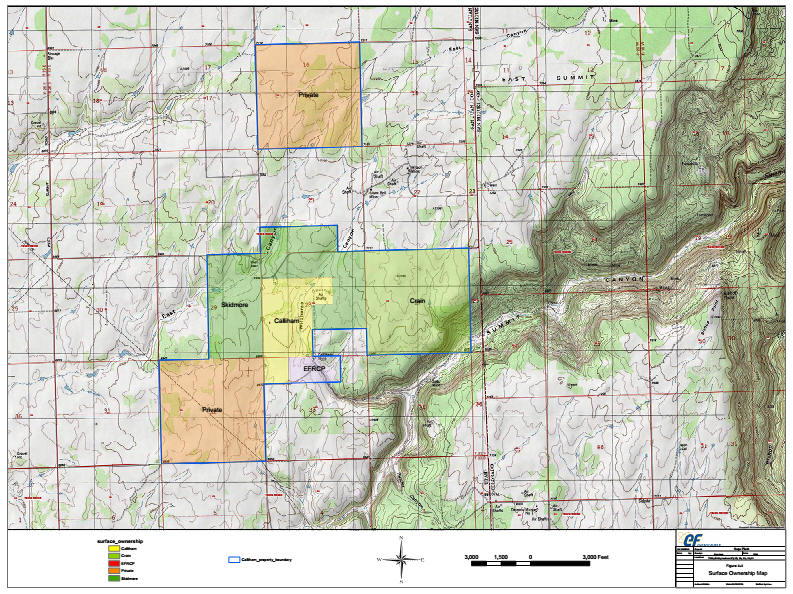
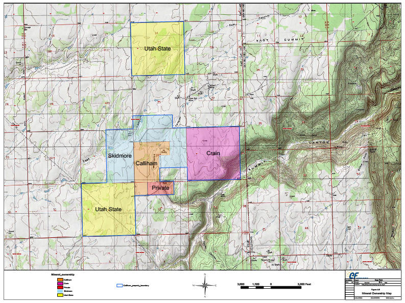


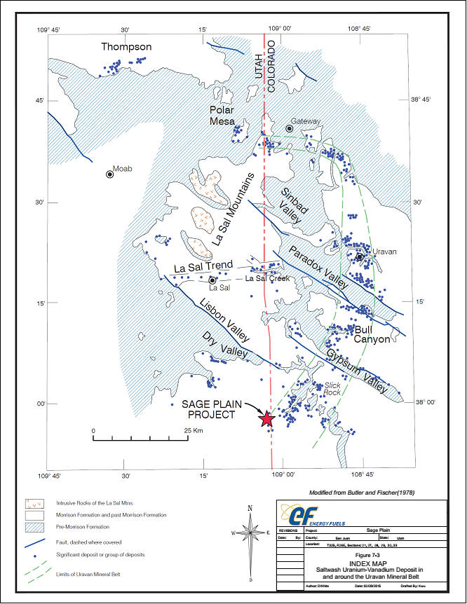

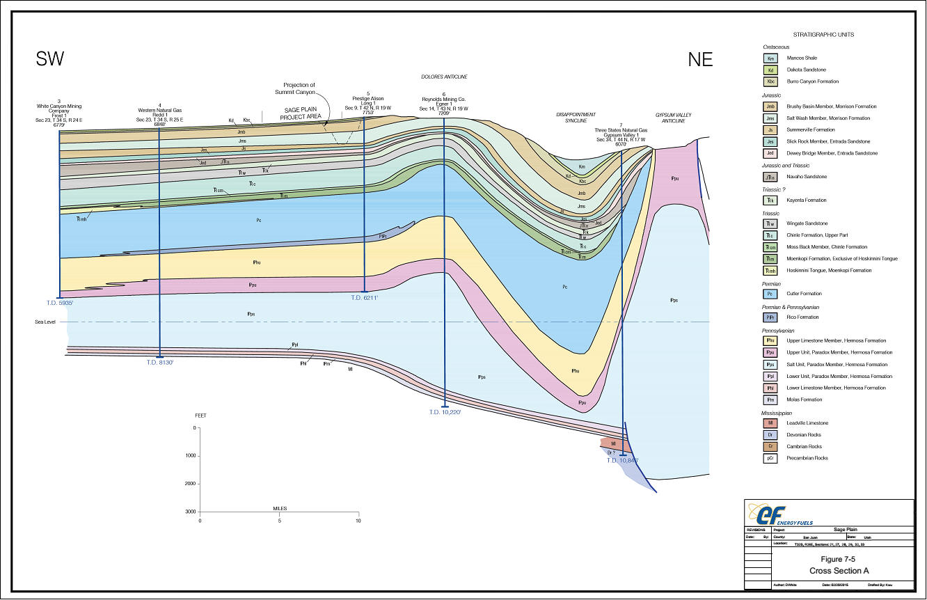

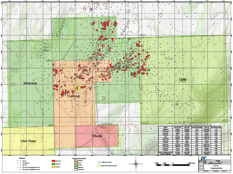


![]()
| ROCA HONDA RESOURCES, LLC |
| TECHNICAL REPORT ON THE |
| ROCA HONDA PROJECT, |
| MCKINLEY COUNTY, |
| STATE OF NEW MEXICO, U.S.A. |
NI 43-101 Report
Qualified Person:
Barton G. Stone,
C.P.G.
Robert Michaud, P.Eng.
Stuart Collins,
P.E.
Mark B. Mathisen, C.P.G.
Harold R. Roberts, P.E., COO
Energy Fuels
| February 27, 2015 |
| RPA Inc. 55 University Ave. Suite 501 I Toronto, ON, Canada M5J 2H7 I T + 1 (416) 947 0907 www.rpacan.com |
| Report Control Form | |||||
| Document Title |
Technical Report on the Roca Honda
Project, McKinley | ||||
|
| |||||
| Client Name & Address |
Roca Honda Resources, LLC
| ||||
|
|
|
|
|
| |
| Document Reference |
|
Status
& |
Final |
| |
|
|
|
| |||
| Issue Date |
February 27, 2015 |
|
|
| |
|
|
|
|
|
| |
| Lead Authors |
Barton G. Stone, P.Geo.
|
|
(Signed) | ||
|
|
|
|
|
| |
| Peer Reviewer |
Deborah McCombe, P.Geo.
|
|
(Signed) | ||
|
|
|
|
|
| |
| Project Manager Approval
|
Stuart E. Collins, P.E.
|
|
(Signed) | ||
|
|
|
|
|
| |
| Project Director Approval
|
Richard J. Lambert
|
|
(Signed) | ||
|
|
|
|
|
| |
| Report Distribution |
Name |
No. of Copies | |||
|
|
|
|
|
| |
|
Client |
| ||||
Roscoe Postle (USA) Ltd.
143 Union Boulevard, Suite
505
Lakewood, CO, USA 80228
T (303) 330-095
F (303) 330-0949
[email protected]
 |
www.rpacan.com |
TABLE OF CONTENTS
| PAGE | |||
| 1 | SUMMARY | 1-1 | |
| Executive Summary | 1-1 | ||
| Technical Summary | 1- 17 | ||
| 2 | INTRODUCTION | 2-1 | |
| 3 | RELIANCE ON OTHER EXPERTS | 3-1 | |
| 4 | PROPERTY DESCRIPTION AND LOCATION | 4-1 | |
| 5 | ACCESSIBILITY, CLIMATE, LOCAL RESOURCES, INFRASTRUCTURE AND PHYSIOGRAPHY | 5-1 | |
| 6 | HISTORY | 6-1 | |
| Roca Honda Ownership History | 6-1 | ||
| Roca Honda Exploration History | 6-2 | ||
| Roca Honda Historic Resource Estimates | 6-4 | ||
| White Mesa Mill Ownership History | 6-4 | ||
| White Mesa Mill Operations History | 6-5 | ||
| 7 | GEOLOGICAL SETTING AND MINERALIZATION | 7-1 | |
| Regional Geology | 7-1 | ||
| Local and Property Geology | 7-5 | ||
| Mineralization | 7- 14 | ||
| 8 | DEPOSIT TYPES | 8-1 | |
| 9 | EXPLORATION | 9-1 | |
| Exploration Potential | 9-1 | ||
| 10 | DRILLING | 10-1 | |
| RHR Drilling | 10-3 | ||
| Gamma Logging Procedures and Verification | 10-5 | ||
| Surveys | 10-5 | ||
| Recovery | 10-6 | ||
| 11 | SAMPLE PREPARATION, ANALYSES AND SECURITY | 11-1 | |
| Historic Sampling Methods | 11-1 | ||
| RHR Sampling | 11-5 | ||
| 12 | DATA VERIFICATION | 12-1 | |
| Historic Quality Assurance and Quality Control | 12-1 | ||
| RHR Quality Assurance and Quality Control | 12-1 | ||
| Data Verification 2004 to 2008 | 12-3 | ||
| RPA Data Verification 2010 to 2011 | 12-4 | ||
| 13 | MINERAL PROCESSING AND METALLURGICAL TESTING | 13-1 | |
| Mineralized Sand Zones | 13-1 | ||
| Roca Honda Resources, LLC– Roca Honda Project, Project #2438 | |
| NI 43-101 Technical Report– February 27, 2015 | Page i |
| |
www.rpacan.com |
| Historical Metallurgical Testing | 13-2 | |
| Conclusions | 13-5 | |
| 14 | MINERAL RESOURCE ESTIMATE | 14-1 |
| Summary | 14-1 | |
| Database | 14-2 | |
| Lithology Wireframe Models | 14-4 | |
| Mineralization Wireframe Models | 14-5 | |
| Radiometric Statistics | 14-8 | |
| Grade Capping | 14-8 | |
| Sample Composites | 14-12 | |
| Block Model Parameters | 14-14 | |
| Density | 4-14 | |
| Grade Estimation | 14-15 | |
| Block Grade Validation | 14-17 | |
| Resource Classification | 14-19 | |
| Mineral Resource Estimate | 14-26 | |
| 15 | MINERAL RESERVE ESTIMATE | 15-1 |
| 16 | MINING METHODS | 16-1 |
| Mining Operations | 16-2 | |
| Mining Method | 16-2 | |
| Mine Design | 16-8 | |
| Underground Mobile Equipment | 16-20 | |
| Mine Infrastructure | 16-21 | |
| Production Schedule | 16-33 | |
| Health and Safety | 16-36 | |
| Future Mining | 16-38 | |
| 17 | RECOVERY METHODS | 17-1 |
| Ore Receiving | 17-5 | |
| Grinding | 17-5 | |
| Leaching | 17-5 | |
| Counter Current Decantation | 17-6 | |
| Tailings Management | 17-6 | |
| Solvent Extraction | 17-7 | |
| Precipitation, Drying and Packaging | 17-7 | |
| 18 | PROJECT INFRASTRUCTURE | 18-1 |
| Roca Honda Roads and Access | 18-1 | |
| Material Handling and Storage | 18-2 | |
| Product Shipments | 18-2 | |
| Mine and Mill Facilities | 18-2 | |
| 19 | MARKET STUDIES AND CONTRACTS | 19-1 |
| Markets | 19-1 | |
| Supply | 19-1 | |
| Demand | 19-2 |
| Roca Honda Resources, LLC– Roca Honda Project, Project #2438 | |
| NI 43-101 Technical Report– February 27, 2015 | Page ii |
| |
www.rpacan.com |
| Price | 19-2 | |
| Contracts | 19-4 | |
| 20 | ENVIRONMENTAL STUDIES, PERMITTING, AND SOCIAL OR COMMUNITY IMPACT | 20-1 |
| Roca Honda Resources Environmental Policy | 20-1 | |
| Roca Honda | 20-2 | |
| Project Permitting | 20-10 | |
| Mine Closure Requirements | 20-16 | |
| 21 | CAPITAL AND OPERATING COSTS | 21-1 |
| Capital Cost Estimate | 21-1 | |
| Operating Cost Estimate | 21-4 | |
| 22 | ECONOMIC ANALYSIS | 22-1 |
| 23 | ADJACENT PROPERTIES | 23-1 |
| 24 | OTHER RELEVANT DATA AND INFORMATION | 24-1 |
| 25 | INTERPRETATION AND CONCLUSIONS | 25-1 |
| 26 | RECOMMENDATIONS | 26-1 |
| 27 | REFERENCES | 27-1 |
| 28 | DATE AND SIGNATURE PAGE | 28-1 |
| 29 | CERTIFICATE OF QUALIFIED PERSON | 29-1 |
LIST OF TABLES
| PAGE | ||
| Table 1-1 | Mineral Resources – February 4, 2015 | 1-3 |
| Table 1-2 | Proposed Budget - Phase 1 | 1-7 |
| Table 1-3 | Proposed Budget - Phase 2 | 1-8 |
| Table 1-4 | RPA Cash Flow Analysis | 1- 10 |
| Table 1-5 | Sensitivity Analysis | 1- 14 |
| Table 1-6 | Major Differences between the 2012 Roca Honda PEAand the 2015 Roca Honda PEA | 1-15 |
| Table 1-7 | Financial Comparison between the 2012 Roca Honda PEA and the 2015 Roca Honda PEA | 1-15 |
| Table 1-8 | Capital Cost Estimate | 1-24 |
| Table 1-9 | Operating Cost Estimate | 1-25 |
| Table 7-1 | Typical Stratigraphic Thickness Data for the Project Area | 7-6 |
| Table 10-1 | Summary of Drilling | 10-1 |
| Table 11-1 | RHR Gamma-ray Results | 11-6 |
| Table 11-2 | Core Sample Results | 11-8 |
| Table 12-1 | Independent Survey Check | 12-5 |
| Table 12-2 | Independent Core Gamma-Ray Check | 12-5 |
| Table 12-3 | Gamma Log vs. Core Lithology | 12-8 |
| Table 12-4 | Gamma Log vs. Core Sample Analyses | 12-9 |
| Roca Honda Resources, LLC– Roca Honda Project, Project #2438 | |
| NI 43-101 Technical Report– February 27, 2015 | Page iii |
| |
www.rpacan.com |
| Table 13-1 | Metallurgical Recovery by Zone | 13-1 |
| Table 13-2 | Mount Taylor Processing Data | 13-4 |
| Table 14-1 | Mineral Resources – February 4, 2015 | 14-2 |
| Table 14-2 | Resource Database | 14-3 |
| Table 14-3 | Grade Statistics | 14-8 |
| Table 14-4 | Mineralized wireframe Composite Statistics | 14-12 |
| Table 14-5 | Block Model Extents | 14-14 |
| Table 14-6 | Density Determination of Core Samples | 14-15 |
| Table 14-7 | Vulcan Domain Search Parameters | 14-16 |
| Table 14-8 | Grade Estimation Parameters | 14-17 |
| Table 14-9 | Mineral Resource Estimate at – FebruARy 4, 2015 | 14-26 |
| Table 16-1 | Key Life of Mine Production Statistics | 16-4 |
| Table 16-2 | Mine Equipment Summary | 16-20 |
| Table 16-3 | Mine Surface Infrastructure Space Requirements – Buildings | 16-22 |
| Table 16-4 | Estimated Electrical Load – Mine only | 16-24 |
| Table 16-5 | Annual Production Statistics from Life-of -Mine Schedule | 16-35 |
| Table 18-1 | White Mesa Mill Plant Estimated Electrical Load | 18-4 |
| Table 18-2 | Surface Equipment Fleet | 18-7 |
| Table 20-1 | Major and Minor Roca Honda Permits | 20-12 |
| Table 21-1 | Capital Cost Estimate | 21-1 |
| Table 21-2 | Surface Infrastructure Indirect Cost Estimate and Total Indirect Cost Estimate | 21-3 |
| Table 21-3 | Operating Cost Estimate | 21-4 |
| Table 21-4 | Underground Mine Cost Summary | 21-6 |
| Table 21-5 | Mill Operating Cost Details BY Area | 21-7 |
| Table 21-6 | Mill Operating Reagent Usage Details | 21-8 |
| Table 21-7 | Surface Maintenance Costs | 21-9 |
| Table 21-8 | Administration Costs | 21-9 |
| Table 21-9 | Power Generation Costs | 21-10 |
| Table 21-10 | Mine and Mill Staff Requirements | 21-11 |
| Table 22-1 | Project Economics Summary Base Case (No Toll Milling) | 22-2 |
| Table 22-2 | Cash Flow Summary | 22-5 |
| Table 22-3 | Sensitivity Analysis | 22-9 |
| Table 22-4 | Major Differences between the 2012 Roca Honda PEA and the 2015 Roca Honda PEA | 22-10 |
| Table 22-5 | Financial Comparison between the 2012 Roca Honda PEA and the 2015 Roca Honda PEA | 22-10 |
| Table 23-1 | “Non-Reserve” Mineralized Material– URI’s Sections 13, 15, and 17 | 23-1 |
| Table 25-1 | Mineral Resources – February 4, 2015 | 25-2 |
| Table 26-1 | Proposed Budget - Phase 1 | 26-3 |
| Table 26-2 | Proposed Budget - Phase 2 | 26-3 |
LIST OF FIGURES
| PAGE | ||
| Figure 1-1 | Summary of Roca Honda Pre-tax Sensitivity Analysis | 1- 13 |
| Figure 1-2 | Comparison of 2015 Roca Honda PEA at Different Uranium Prices to 2012 Roca Honda PEA at US๛/lb | 1-16 |
| Roca Honda Resources, LLC– Roca Honda Project, Project #2438 | |
| NI 43-101 Technical Report– February 27, 2015 | Page iv |
| |
www.rpacan.com |
| Figure 4-1 | Roca Honda Mine Location Map | 4-5 |
| Figure 4-2 | White Mesa Mill Location and Property Map | 4-6 |
| Figure 4-3 | Roca Honda Mine, White Mesa Mill, and Proposed Haul Route Location Map . | 4-7 |
| Figure 4-4 | Roca Honda Property Map | 4-8 |
| Figure 4-5 | Roca Honda Proposed Pipeline Route | 4-9 |
| Figure 7-1 | Regional Geological Map of Northwestern New Mexico | 7-3 |
| Figure 7-2 | Regional Structural Features | 7-4 |
| Figure 7-3 | Property Geology | 7- 11 |
| Figure 7-4 | Typical Stratigraphy of the Roca Honda Project Area | 7- 12 |
| Figure 7-5 | Typical Upper-Jurassic Stratigraphy of the Roca Honda Project Area | 7-13 |
| Figure 9-1 | Exploration Potential | 9-3 |
| Figure 10-1 | Drill Hole Location Map | 10-2 |
| Figure 10-2 | Stratigraphy of Section 16 Shaft Core Hole | 10-4 |
| Figure 11-1 | Typical Historical Kerr-McGee Gamma-Ray Logs | 11-2 |
| Figure 14-1 | Block Model Boundaries | 14-7 |
| Figure 14-2 | Histogram Plot | 14-9 |
| Figure 14-3 | Log Normal Probability Plot | 14-10 |
| Figure 14-4 | Cumulative Frequency Plot | 14-11 |
| Figure 14-5 | Roca Honda Longitudinal Section | 14-18 |
| Figure 14-6 | A Sand Resource Classification | 14-21 |
| Figure 14-7 | B1 Sand Resource Classification | 14-22 |
| Figure 14-8 | B2 Sand Resource Classification | 14-23 |
| Figure 14-9 | C Sand Resource Classification | 14-24 |
| Figure 14-10 | D Sand Resource Classification | 14-25 |
| Figure 14-11 | Roca Honda Resource Grade vs. Tons | 14-28 |
| Figure 16-1 | Roca Honda Mine Site Layout | 16-5 |
| Figure 16-2 | White Mesa Mill Layout | 16-6 |
| Figure 16-3 | Access Ramp Locations | 16-14 |
| Figure 16-4 | Southwest Deposit Access Ramp Locations | 16-15 |
| Figure 16-5 | Northeast Deposit Access Ramp Locations | 16-16 |
| Figure 16-6 | Step-Room -and-Pillar Mining Method | 16-17 |
| Figure 16-7 | Drift-and-Fill Mining Method | 16-18 |
| Figure 17-1 | White Mesa Mill Location Map | 17-2 |
| Figure 17-2 | White Mesa Mill - Site Map | 17-3 |
| Figure 17-3 | White Mesa Mill Block Diagram Flow Sheet | 17-4 |
| Figure 19-1 | Average Annual Price – Spot Market 2000-2014 | 19-3 |
| Figure 19-2 | Major Bank Uranium Price Forecast – 2013 | 19-4 |
| Figure 20-1 | USFS TCP and New Mexico TCP Boundaries | 20-8 |
| Figure 22-1 | Summary of Roca Honda Sensitivity Analysis (Pre-tax) | 22-8 |
| Figure 22-2 | Comparison of 2015 Roca Honda PEA at Different Uranium Prices to 2012 Roca Honda PEA at US$75/lb | 22-11 |
| Figure 23-1 | Adjacent Properties | 23-3 |
| Roca Honda Resources, LLC– Roca Honda Project, Project #2438 | |
| NI 43-101 Technical Report– February 27, 2015 | Page v |
| |
www.rpacan.com |
1 SUMMARY
EXECUTIVE SUMMARY
Roscoe Postle Associates Inc. (RPA) was retained by Roca Honda Resources, LLC (RHR) to prepare an Technical Report on the Roca Honda uranium project (the Project), located in McKinley County, New Mexico. The purpose of this report is to update the Preliminary Economic Assessment (PEA) of the Project. This Technical Report conforms to National Instrument 43-101 Standards of Disclosure for Mineral Projects (NI 43-101). RPA has visited the property multiple times, with the most recent site visit on February 15-17, 2015.
In 2007, Strathmore Minerals Corp. (Strathmore) (60%) and Sumitomo Corporation of Japan (Sumitomo) (40%) entered into a joint venture, Roca Honda Resources, LLC, to develop the Roca Honda deposit. In 2009, RHR submitted its Roca Honda Mine permit application to the New Mexico Mining and Minerals Division and U.S. Forest Service. This permit was deemed administratively complete by the regulatory agencies, and is now undergoing technical review. In August 2013, Energy Fuels Resources (USA) Inc. (Energy Fuels) acquired all of the assets of Strathmore, which is now a wholly-owned subsidiary of Energy Fuels. The Project is held by RHR, as the operator.
RPA has previously prepared a PEA for the Project, and the supporting NI 43-101 Technical Report was published in 2012. This updated PEA includes an underground operation using both step room-and-pillar stoping in the lower grade zones and drift-and-fill stoping in the higher grade sections. Ore processing will take place at the White Mesa Mill operated by Energy Fuels Resources (USA) Inc. under a toll milling agreement. The White Mesa Mill is an existing conventional uranium mill including agitated leaching, counter current decantation, solvent extraction, and precipitation. Based on the current Mineral Resources, the mine life will be nine years at an average mining rate of 1,085 tons per day (stpd). The mine is located in McKinley County, New Mexico, and the White Mesa Mill is located in San Juan County, Utah.
This report is considered by RPA to meet the requirements of a PEA as defined in Canadian NI 43-101 regulations. The economic analysis contained in this report is based, in part, on Inferred Resources, and is preliminary in nature. Inferred Resources are considered too geologically speculative to have mining and economic considerations applied to them and to be categorized as Mineral Reserves. There is no certainty that the reserves development, production, and economic forecasts on which this PEA is based will be realized.
| Roca Honda Resources, LLC– Roca Honda Project, Project #2438 | |
| NI 43-101 Technical Report– February 27, 2015 | Page 1-1 |
| |
www.rpacan.com |
CONCLUSIONS
RPA offers the following conclusions regarding the Roca Honda Project:
GEOLOGY AND MINERAL RESOURCES
| • |
The Project is a significant high grade uranium deposit. | |
|
| ||
| • |
Uranium mineralization at the Project is associated with large amounts of organic/high carbon material in sandstones. | |
|
| ||
| • |
Drilling to date has intersected localized, high-grade mineralized zones contained within five sandstone units of the Westwater Canyon Member of the Morrison Formation. | |
|
| ||
| • |
The sampling, sample preparation, and sample analysis programs are appropriate for the type of mineralization. | |
|
| ||
| • |
Although continuity of mineralization is variable, drilling to date confirms that local continuity exists within individual sandstone units. | |
|
| ||
| • |
No significant discrepancies were identified with the survey location, lithology, and electric and gamma log interpretations data in historic holes. | |
|
| ||
| • |
No significant discrepancies were identified with the lithology and electric and gamma log data interpretations in RHR holes. | |
|
| ||
| • |
Descriptions of recent drilling programs, logging, and sampling procedures have been well documented by RHR, with no significant discrepancies identified. | |
|
| ||
| • |
There is a low risk of depletion of chemical uranium compared to radiometrically determined uranium in the Roca Honda deposit. | |
|
| ||
| • |
RPA is of the opinion that the quality assurance and quality control (QA/QC) procedures undertaken support the integrity of the database used for Mineral Resourceestimation. | |
|
| ||
| • |
The resource database is valid and suitable for Mineral Resource estimation. | |
|
| ||
| • |
The Mineral Resource estimate and classification are in accordance with the Canadian Institute of Mining, Metallurgy and Petroleum Definition Standards on Mineral Resources and Mineral Reserves dated May 10, 2014 (CIM definitions) incorporated in NI 43-101. The resource model and underlying data have not changed since the 2012 Technical Report, however, RPA has reported Mineral Resources at a higher cut- off grade, consistent with the production scenario proposed in this PEA. Table 1-1 summarizes the Mineral Resources for the Roca Honda Project. |
| Roca Honda Resources, LLC– Roca Honda Project, Project #2438 | |
| NI 43-101 Technical Report– February 27, 2015 | Page 1-2 |
| |
www.rpacan.com |
TABLE 1-1 MINERAL RESOURCES – FEBRUARY 4, 2015
Roca Honda Resources LLC – Roca Honda Project
| Classification | Tons (000) |
Grade U3O8 (%) |
Pounds U3O8 (000) |
| Measured Resources | 208 | 0.477 | 1,984 |
| Indicated Resources | 1,303 | 0.483 | 12,580 |
| Total Measured and Indicated Resources | 1,511 | 0.482 | 14,564 |
| Inferred Resources | 1,198 | 0.468 | 11,206 |
| Notes: | ||
| 1. | CIM definitions were followed for Mineral Resources. | |
| 2. | Mineral Resources are estimated using an undiluted cut-off grade of 0.19% U3O8. | |
| 3. | A minimum mining thickness of six feet was used, along with $241/ton operating cost and $65/lb U3O8 cut-off grade and 95% recovery. | |
| 4. | Mineral Resources that are not Mineral Reserves do not have demonstrated economic viability. | |
| 5. | Numbers may not add due to rounding. | |
| • |
RPA did not update the mine design and production schedule, which was developed using a cut-off grade of 0.13%U3O8. The previous work was reviewed, and it was determined that stopes remain above the updated cut-off grade of 0.19% U3O8. Some material below 0.19% U3O8 is included within the stope designs, and should be considered incremental material. | |
| • |
In RPA’s opinion, a stope re-design at a higher cut-off grade would remove some incremental material, raise the average production grade, and improve the cash flow, although the mine life would be somewhat shorter. | |
| • |
RPA is not aware of any known environmental, permitting, legal, title, taxation, socioeconomic,marketing, political, or other relevant factors that could materially affect the current resource estimate. |
MINING
| • | The mineralization is relatively flat-lying, and will be mined with a combination of step room-and-pillar and drift-and-fill stoping. | |
| • | In the development of the Mineral Resource estimate for this PEA, RPA used a diluted cut-off grade of 0.110% U3O8, a minimum mining thickness of six feet, and the historical mining recovery of 85% for the step room-and-pillar mining method and 90% recovery for the drift-and-fill mining method. | |
| • | The PEA is based on 2.033 million tons of Measured and Indicated Resources at a diluted grade of 0.365% U3O8 and 1.400 million tons of Inferred Resources at a diluted grade of 0.355% U3O8. RPA notes that Inferred Mineral Resources are considered too geologically speculative to have mining and economic considerations applied to them and to be categorized as Mineral Reserves. |
| Roca Honda Resources, LLC– Roca Honda Project, Project #2438 | |
| NI 43-101 Technical Report– February 27, 2015 | Page 1-3 |
| |
www.rpacan.com |
| • |
RPA considers the mining plan to be relatively simple and the mining conditions are expected to be acceptable after the ground is sufficiently dewatered. | |
|
| ||
| • |
Mining is dependent upon the use of a suitable backfill, assumed to be backfill with cement added as a binder. Initial test work to demonstrate that a suitable backfill will be generated before and during the mine development period needs to be completed. |
PROCESSING
| • |
Mineral processing test work indicates that uranium can be recovered in an acid leaching circuit after grinding to 80% minus 28 mesh with estimated recoveries of 95% from the mineralized material. Feed to the semi-autogenous grinding (SAG) mill is assumed to be F80 of three inch. The comminution circuit at White Mesa Mill can produce P80 28-mesh sized material. | |
|
| ||
| • |
White Mesa Mill uses an atmospheric hot acid leach followed by counter current decantation (CCD). This in turn is followed by a clarification stage, which precedes the solvent extraction (SX) circuit. Kerosene containing iso-decanol and tertiary amines extracts the uranium and vanadium from the aqueous solution in the SX circuit. Salt and sulfuric acid are then used to strip the uranium from the organic phase. | |
|
| ||
| • |
After extraction of the uranium values from the aqueous solution in SX, uranium is precipitated with anhydrous ammonia, dissolved, and re-precipitated to improve product quality. The resulting precipitate is then washed and dewatered using centrifuges to produce a final product called "yellowcake." The yellowcake is dried in a multiple hearth dryer and packaged in drums weighing approximately 800 lb to 1,000 lb for shipping to converters. | |
|
| ||
| • |
The yellowcake (U3O8 concentrate) will be stored in 55 gallon drums at the White Mesa Mill until shipped off-site. | |
|
| ||
| • |
Tailings from the acid leach plant will be stored in 40-acre tailing cells located in the southwest and southern portion of the mill site. | |
|
| ||
| • |
Process solutions will be stored in the evaporation cells for reuse and excess solutions will be allowed to evaporate. |
INFRASTRUCTURE
| • |
The Roca Honda site is easily accessed via existing paved highways and gravel roads that can be readily improved to accommodate haul trucks. | |
|
| ||
| • |
The initial mine site power will be provided by an upgrade to a 25 kV power line with backup capacity supplied by a diesel, generating station. The diesel plant design is based upon having two spare units at any given time. | |
|
| ||
| • |
The White Mesa Mill is currently fully operational. Additional tailings storage capacity is required at White Mesa Mill for the Roca Honda ore. Costs for construction of additional capacity are included in the estimated milling operating cost. |
| Roca Honda Resources, LLC– Roca Honda Project, Project #2438 | |
| NI 43-101 Technical Report– February 27, 2015 | Page 1-4 |
| |
www.rpacan.com |
ENVIRONMENT
| • |
Extensive baseline studies have been completed for the Project’s proposed mine location. All required permits for the White Mesa Mill to operate are in place. | |
|
| ||
| • |
The Draft Environmental Impact Statement (EIS) was published by the United States Forest Service (USFS) in February 2013 with an expected Record of Decision (ROD) and Final EIS in late 2016. A mine permit is expected to be issued following the ROD and Final EIS in early 2017. | |
|
| ||
|
| ||
| • |
Rock characterization studies indicate that waste rock from the Project is not an acid producer. | |
|
| ||
| • |
Environmental considerations are typical of underground mining and processing facilities and are being addressed in a manner that is reasonable and appropriate for the stage of the Project. |
ECONOMICS
| • |
The uranium prices used in the PEA are higher (US$65.00 per pound) than the current uranium price (February 24, 2015) of US$37.15 per pound. The prices are based on independent, third-party and market analysts’ average forecasts for 2015, and the supply and demand projections are from 2011 to 2015. In RPA’s opinion, these long- term price forecasts are a reasonable basis for estimation of Mineral Resources. | |
|
| ||
| • |
Income taxes and New Mexico mining royalties on the Project are dependent on the selected method of depreciation of capital, and may also be reduced by application of credits accumulated by RHR. In RPA’s opinion, there is potential to improve the after- tax economic results, as the Project is advanced. |
RISKS
| • |
There are potential risks associated with the fluctuating price of uranium, socio- economic community relations, and the issue of water, dewatering, and disposal of mine water. Based on previous mining history in the area, risks associated with water can be managed. |
RECOMMENDATIONS
RPA recommends that Roca Honda Resources advance the Roca Honda Project to the Prefeasibility Study stage, and continue the New Mexico and Federal permitting processes. Specific recommendations by area are as follows.
GEOLOGY
| • |
Although RPA is of the opinion that there is a relatively low risk in assuming that density of mineralized zones is similar to that reported in mining operations east and west of the Roca Honda property, additional density determinations should be carried out, particularly in the mineralized zones, to confirm and support future resource estimates. |
| Roca Honda Resources, LLC– Roca Honda Project, Project #2438 | |
| NI 43-101 Technical Report– February 27, 2015 | Page 1-5 |
| |
www.rpacan.com |
| • |
Although there is a low risk of depletion of chemical uranium compared to radiometrically determined uranium in the Roca Honda mineralization, additional sampling and analyses should be completed to supplement results of the limited disequilibrium testing to date. | |
|
| ||
| • |
In the future, implement a QA/QC protocol for sample analysis that includes the regular submission of blanks and standards. | |
|
| ||
| • |
Review additional fault modelling once additional data have been obtained. | |
|
| ||
| • |
Complete additional confirmation drilling at the earliest opportunity to confirm historic drill hole data on all zones. |
RESOURCES
| • |
Complete further definition drilling in the Mineral Resource areas to increase the quantity and quality of the resources and improve the overall confidence, i.e., resource classification (Measured, Indicated, and Inferred). | |
|
| ||
| • |
Include one-half foot assays in the geologic database for future grade shell analysis. |
HYDROLOGY
| • |
Continue to gather data, which will improve knowledge about the local and regional aquifers. | |
|
| ||
| • |
Continue to update the regional groundwater model as new data becomes available to determine the impacts that the depressurization of the Roca Honda Project will have on local and regional aquifers. The regional groundwater model has been accepted by both the USFS and New Mexico Office of the State Engineer. |
MINING
| • |
Geotechnical designs are based on the laboratory testing of only a limited number of core samples. Additional sampling and testing should be pursued in concert with the definition drilling program. Boreholes should be located on the centerline of the various proposed ventilation shafts. The cores from these holes will define the different lithologies to be encountered, and provide samples for rock strength testing and other needed geotechnical design information. The geotechnical study on the proposed shaft core hole was completed in 2012. More detailed designs and cost estimates should be completed. | |
|
| ||
| • |
Investigate more thoroughly the applicability of using roadheaders, and other selective mining methods that may reduce dilution for development and stope mining, which will reduce the tonnage and increase the grade of material shipped and processed at White Mesa Mill. | |
|
| ||
| • |
Pursue the acquisition or joint venturing of potential extensions of the mineralized zones onto adjacent land. The Project is sensitive to total resources tonnage and grade, i.e., total pounds of contained uranium. Potential acquisitions could impact the preferred locations of underground mine access, surface infrastructure, and possibly the processing facilities. |
| Roca Honda Resources, LLC– Roca Honda Project, Project #2438 | |
| NI 43-101 Technical Report– February 27, 2015 | Page 1-6 |
| |
www.rpacan.com |
PROCESSING
| • |
Obtain representative metallurgical samples for site specific test work including disequilibrium analysis of the Roca Honda Sand Horizons: A, B, C and D Sands. | |
|
| ||
| • |
Finalize processing parameters to be used at the White Mesa Mill . |
PROPOSED PROGRAM AND BUDGET
RPA recommends a two-phase work program and budget for the Roca Honda property, with Phase 2 being contingent on the outcome of Phase 1. The focus of the Phase 1 program is to continue the permitting process for the Project with State and Federal Agencies as well as continue environmental, engineering, and design studies to support the permitting process. The Phase 2 program includes additional drilling to increase and upgrade existing Mineral Resources, and mine design. The work programs and budgets are summarized in Tables 1-2 and 1-3.
TABLE 1-2 PROPOSED BUDGET - PHASE 1
Roca Honda
Resources LLC – Roca Honda Project
| Proposed Budget Item | US$ | ||
| Legal/Regulatory | 301,500 | ||
| Project Management/Staff Cost | 419,260 | ||
| Expense Accounts/Travel Costs | 25,525 | ||
| Holding Costs | 84,320 | ||
| Access Fees | 300,000 | ||
| Environmental Studies | 40,000 | ||
| Engineering Studies | 310,000 | ||
| Community Relations | 13,000 | ||
| Permitting | 461,000 | ||
| Communications | 8,820 | ||
| Transportation | 7,200 | ||
| Subtotal | 1,970,625 | ||
| Contingency (10%) | 197,063 | ||
| TOTAL | 2,167,688 |
| Roca Honda Resources, LLC– Roca Honda Project, Project #2438 | |
| NI 43-101 Technical Report– February 27, 2015 | Page 1-7 |
| |
www.rpacan.com |
TABLE 1-3 PROPOSED BUDGET - PHASE 2
Roca Honda
Resources LLC – Roca Honda Project
| Proposed Budget Item | US$ | ||
| Legal/Regulatory | 100,000 | ||
| Project Management/Staff Cost | 400,000 | ||
| Expense Accounts/Travel Costs | 25,000 | ||
| Holding Costs | 90,000 | ||
| Access Fees | 200,000 | ||
| Drilling (32 holes ~60,000 ft) | 2,361,000 | ||
| Assaying/Geophysical Logging | 124,000 | ||
| Environmental Studies | 50,000 | ||
| Metallurgical Test Work | 200,000 | ||
| Community Relations | 100,000 | ||
| Geotechnical Analysis | 200,000 | ||
| Reclamation Bonding | 400,000 | ||
| Communications | 20,000 | ||
| Transportation | 30,000 | ||
| Subtotal | 4,300,000 | ||
| Contingency (10%) | 430,000 | ||
| TOTAL | 4,730,000 |
ECONOMIC ANALYSIS
The economic analysis contained in this report includes Inferred Resources,and is preliminary in nature. Inferred Resources are considered too geologically speculative to have mining and economic considerations applied to them and to be categorized as Mineral Reserves. There is no certainty that the reserves development, production, and economic forecasts on which this PEA is based will be realized.
A pre-tax cash flow projection has been generated from the Life of Mine (LoM) schedule and capital and operating cost estimates, and is summarized in Table 1-4. A summary of the key criteria is provided below.
REVENUE
| • | Average of 1,085 stpd of Roca Honda material (base case). | |
| • | Waste mining of 0.82 Mt. | |
| • | Mill recovery averaging 95%. | |
| • | Metal price: US$65.00 per pound U3O8. | |
| • | Revenue is recognized at the time of production. |
| Roca Honda Resources, LLC– Roca Honda Project, Project #2438 | |
| NI 43-101 Technical Report– February 27, 2015 | Page 1-8 |
| |
www.rpacan.com |
COSTS
| • | Pre-production period of 54 months. | |
| • | Mine life of nine years. | |
| • | Pre-production capital cost of US$254 million including contingency of US$45 million. | |
| • | Toll milling charge of $35.90 per ton. | |
| • | Sustaining capital costs of US$72 million. | |
| • | Roca Honda closure capital cost of approximately US$3.4 million. | |
| • | Total mine life capital cost of US$326 million including contingency. | |
| • | Total LoM operating cost of US$829 million. |
ROYALTIES
| • | There is a New Mexico mining royalty payable on the “value” of mineral production for | ||
| New Mexico state leases. The royalty is based upon the operating cash flow less a | |||
| development allowance, depreciation, and a processing allowance. | |||
| • | New Mexico mining and private royalties on value of minerals extracted as shown | ||
| below: | |||
| o | Notional Gross Royalty (1%); | ||
| o | Section 9 Gross Royalty (1%); and | ||
| o | Section 16 New Mexico State Lease Royalty (5%). | ||
| Roca Honda Resources, LLC– Roca Honda Project, Project #2438 | |
| NI 43-101 Technical Report– February 27, 2015 | Page 1-9 |
| |
www.rpacan.com |
TABLE 1-4 PRE-TAX CASH FLOW SUMMARY Roca Honda Resources, LLC - Roca Honda Project

| Roca Honda Resources, LLC– Roca Honda Project, Project #2438 | |
| NI 43-101 Technical Report– February 27, 2015 | Page 1-10 |
| |
www.rpacan.com |
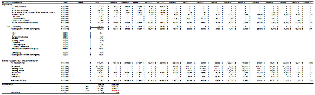
| Roca Honda Resources, LLC– Roca Honda Project, Project #2438 | |
| NI 43-101 Technical Report– February 27, 2015 | Page 1-11 |
| |
www.rpacan.com |
CASH FLOW ANALYSIS
Considering the Project on a stand-alone basis, the base case undiscounted pre-tax cash flow and including contingency totals US$317 million over the mine life, and payback occurs early in the fifth year of production. The average uranium production is 2.7 million pounds of uranium per year (1,450 tons of uranium oxide) with a maximum annual production of 3.9 million pounds.
The pre-tax internal rate of return (IRR) is 12% and the pre-tax net present value (NPV) is as follows:
| • | US$317 million at a 0% discount rate; | |
| • | US$125 million at a 5% discount rate; | |
| • | US$58 million at an 8% discount rate; and | |
| • | US$1 million at a 12% discount rate. |
The net revenue per pound of product is US$62.60, and the operating cost per pound of product is US$35.23/lb
SENSITIVITY ANALYSIS
Project risks can be identified in both economic and non-economic terms. Key economic risks were examined by running cash flow sensitivities:
| • | Uranium Oxide Price | |
| • | Head Grade | |
| • | Recovery | |
| • | Operating Cost per ton milled | |
| • | Capital Cost |
Sensitivity has been calculated over a range of variations based on realistic fluctuations within above listed factors.
The sensitivities are shown in Figure 1-1 and Table 1-5. The Project is most, and equally, sensitive to head grade, uranium price, and recovery, and least, and equally, sensitive to operating cost and capital cost. The sensitivities to metallurgical recovery and head grade are identical to that of price (for all constituents combined) and are therefore plotted on the same line.
| Roca Honda Resources, LLC– Roca Honda Project, Project #2438 | |
| NI 43-101 Technical Report– February 27, 2015 | Page 1-12 |
| |
www.rpacan.com |
FIGURE 1-1 SUMMARY OF ROCA HONDA PRE-TAX SENSITIVITY ANALYSIS

| Roca Honda Resources, LLC– Roca Honda Project, Project #2438 | |
| NI 43-101 Technical Report– February 27, 2015 | Page 1-13 |
| |
www.rpacan.com |
TABLE 1-5 SENSITIVITY ANALYSIS
Roca Honda Resources LLC – Roca Honda Project
| Parameter Variables |
Units | -33% | -13% | Base | 20% | 30% |
| U3O8 Price | $/lb | 43 | 56 | 65 | 78 | 87 |
| Pre-tax NPV @ 8% | ($ millions) | -171 | -34 | 58 | 196 | 287 |
| IRR | % | -11% | 5% | 12% | 20% | 24% |
| Parameter Variables |
-25% | -10% | Base | 10% | 25% | |
| Grade | % | 0.27 | 0.3% | 0.36 | 0.40 | 0.45 |
| Pre-tax NPV @ 8% | ($ millions) | -113 | -10 | 58 | 126 | 229 |
| IRR | % | -3% | 7% | 12% | 16% | 22% |
| Parameter Variables |
-20% | -10% | Base | 2% | 3% | |
| Recovery | % | 76 | 86 | 95 | 97 | 98 |
| Pre-tax NPV @ 8% | ($ millions) | -80 | -11 | 58 | 72 | 79 |
| IRR | % | 1% | 7% | 12% | 13% | 13% |
| Parameter Variables |
-20% | -10% | Base | 10% | 20% | |
| Operating Cost | $ millions | 542 | 678 | 829 | 995 | 1,176 |
| Pre-tax NPV @ 8% | ($ millions) | 192 | 129 | 58 | -20 | -104 |
| IRR % | % | 20% | 16% | 12% | 6% | -2% |
| Parameter Variables |
-30% | -15% | Base | 15% | 30% | |
| Capital Cost | $ millions | 242 | 284 | 327 | 369 | 411 |
| Pre-tax NPV @ 8% | ($ millions) | 120 | 89 | 58 | 27 | -5 |
| IRR | % | 18% | 15% | 12% | 10% | 8% |
COMPARISON WITH THE 2012 PEA
The significant changes between the 2012 PEA and the 2015 PEA are listed in Table 1-6, and the sensitivity financial impacts of these changes are listed in Table 1-7 and Figure 1-2.
RPA notes that the uranium price used for the 2015 PEA is $65/lb and the uranium price used for the 2012 PEA was $75/lb. Table 1-7 shows that if a $75/lb price is used for the 2015 Roca Honda PEA, the pre-tax IRR is only one percent less than the 2012 Roca Honda PEA.
| Roca Honda Resources, LLC– Roca Honda Project, Project #2438 | |
| NI 43-101 Technical Report– February 27, 2015 | Page 1-14 |
| |
www.rpacan.com |
TABLE 1-6 MAJOR DIFFERENCES BETWEEN THE 2012 ROCA
HONDA
PEA AND THE 2015 ROCA HONDA PEA
Roca Honda Resources LLC – Roca Honda
Project
| Item Changed in PEA | 2012 PEA Assumption | 2015 Assumption | Comment |
| Uranium Price | US$75/lb | US$65/lb | |
| Process Plant Location | Peña Ranch, NM | Blanding, UT | |
| Mill Capital Cost | US$120 million | US$0 | |
| (Directs, Indirects, & | |||
| Contingency) | |||
| Ventilation Shaft(s) | Blind Bore | Raise Boring | |
| Method | |||
| Transportation Distance | 25 to 29 road miles | 275 road miles | |
| Transportation Cost | US$4.05/t ore | US$43.50/t ore | |
| (mine to mill) | |||
| Toll Milling Charge of | US$0.00/t ore | US$35.90/t ore | |
| Roca Honda Material | |||
| Water Pipeline | 10 mile Northern Route | 26 mile Southern | |
| Route | |||
| Capital Cost Estimate | US$445 million | US$327 million | |
| (Life of Mine) | |||
| Process Plant | New Construction | Existing – White | |
| Mesa Mill (WMM) | |||
| Process Plant Permitting | Unknown – High Risk – | In place – Low | No NRC license required with |
| Very Long Lead Time to | Risk | the WMM | |
| Obtain NRC | |||
| Process Recovery Used | 94% | 95% | EFR has processed many |
| different types of uranium ores | |||
| at their existing White Mesa Mill. |
TABLE 1-7 FINANCIAL COMPARISON BETWEEN THE 2012 ROCA HONDA
PEA AND THE 2015 ROCA HONDA PEA
Roca Honda Resources LLC – Roca
Honda Project
| Description | Units | Price Sensitivities and Recovery | |||||
| Date of PEA | Feb-15 | Feb-15 | Feb-15 | Feb-15 | Feb-15 | Aug-12 | |
| Uranium Price | US$/lb | 45.00 | 55.00 | 65.00 | 75.00 | 90.00 | 75.00 |
| Processing Recovery | % | 95 | 95 | 95 | 95 | 95 | 94 |
| Pre-tax Cash Flow | $US 000s | (137,472) | 89,965 | 317,403 | 544,840 | 885,997 | 713,087 |
| Pre-tax NPV @ 8% Discount Rate | $US 000s | (153,637) | (47,821) | 57,996 | 163,812 | 322,536 | 220,075 |
| Pre-tax IRR | % | -8 | 4 | 12 | 18 | 26 | 19 |
| Roca Honda Resources, LLC– Roca Honda Project, Project #2438 | |
| NI 43-101 Technical Report– February 27, 2015 | Page 1-15 |
| |
www.rpacan.com |
FIGURE 1-2 COMPARISON OF 2015 ROCA HONDA PEA AT DIFFERENT
URANIUM PRICES TO 2012 ROCA HONDA PEA AT US$75/LB

Energy Fuels believes that the financial risk of permitting a mill in New Mexico is greater than the risk of using the existing White Mesa Mill in Blanding, Utah. In addition, Energy Fuels believes that the capital cost risk is lower using the White Mesa Mill than building a mill near the RocaHonda Mine. Operating costsforthe processingof RocaHonda material at the White Mesa Mill are higher because of the transportation cost from the Roca Honda Mine to the White Mesa Mill.
| Roca Honda Resources, LLC– Roca Honda Project, Project #2438 | |
| NI 43-101 Technical Report– February 27, 2015 | Page 1-16 |
| |
www.rpacan.com |
TECHNICAL SUMMARY
PROPERTY DESCRIPTION AND LOCATION
The Roca Honda uranium project is located approximately three miles northwest of the community of San Mateo, New Mexico, near the southern boundary of McKinley County and north of the Cibola County boundary, and approximately 22 miles by road northeast of Grants, New Mexico. The property is located in the east part of the Ambrosia Lake subdistrict of the Grants Mineral Belt in northwest New Mexico and comprises nearly all of Sections 9, 10, and a narrow strip of Section 11, and the New Mexico State Lease, consisting of Section 16, all in Township 13 North – Range 8 West (T13N-R8W), New Mexico Principal Meridian.
The White Mesa Mill is located on 4,816 acres of private land owned by Energy Fuels. This land is located in Township 37S and 38S Range 22E Salt Lake Principal Meridian. The mill is located approximately six miles south of Blanding, Utah along US Highway 191. Energy Fuels also holds 253 acres of mill site claims and a 320 acre Utah state lease. No facilities are planned on the claims or leased land, which will be used as a buffer to the operations.
LAND TENURE
The Roca Honda property is held by RHR, which is jointly owned by Energy Fuels’ wholly-owned subsidiary Strathmore Resources, U.S. Ltd. (60%) and Sumitomo’s subsidiaries SC Clean Energy and Summit New Energy Holding, LLC (40%). RHR was established on July 26, 2007, when Strathmore formed a limited liability company with Sumitomo and transferred the property to RHR.
The Roca Honda property covers an area of 1,886.5 acres, and includes 63 unpatented lode mining claims in Sections 9 and 10, and one adjoining New Mexico State General Mining Lease in Section 16. The mining claims also extend onto a 9.4 acre narrow strip of Section 11. Strathmore acquired the mining claims on March 12, 2004, from Rio Algom Mining LLC (Rio Algom), a successor to Kerr-McGee Corporation (Kerr-McGee), which had staked the claims in 1965 and had continuously maintained them. The New Mexico State Lease was acquired by David Miller (former Strathmore CEO) on November 30, 2004, and subsequently transferred to Strathmore.
The WhiteMesa Mill is located approximately six miles south of Blanding, Utah on US Highway 191 on a parcel of land encompassing all or part of Sections 21, 22, 27, 28, 29, 32, and 33 of T37S, R22E, and Sections 4, 5, 6, 8, 9, and 16 of Township 38 South, Range 22 East, Salt Lake Base and Meridian. Additional land is controlled by 46 mill site claims. Total White Mesa Mill land holdings are approximately 5,375 acres.
| Roca Honda Resources, LLC– Roca Honda Project, Project #2438 | |
| NI 43-101 Technical Report– February 27, 2015 | Page 1-17 |
| |
www.rpacan.com |
ROCA HONDA EXISTING INFRASTRUCTURE
Old drill roads were previously established across the property, and an electrical line transects the northern half of Section 16 in the Project area. The line continues on the west side of the Project area into Section 17, where it terminates, and on the east side of Section 16 through the northwest quarter of Section 15 and along the southern section boundary of Section 10.
Three monitor water wells were drilled by RHR in 2007, and are located on Section 16.
WHITE MESA MILL INFRASTRUCTURE
The White Mesa Mill was constructed in 1979–1980 and is a fully functioning uranium/vanadium mill. It is the only fully operational and licensed conventional uranium mill in the US. The mill is capable of functioning independent of off-site support except for commercial power from Rocky Mountain Power and supplemental water supply from the City of Blanding, Utah, and the San Juan Water Conservancy District. Off-site infrastructure includes paved highway access from State Highway 191, and right-of-ways for commercial power and a water supply pipeline from Recapture Reservoir, which brings up to 1,000 acre-feet of water per year to the mill site. The mill also has four deep (2,000+ ft) water supply wells which supply process water during normal operations. In addition to the mill processing equipment, which includes the grinding and leaching circuits, CCD (liquid–solid separation), solvent extraction, and precipitation and drying circuits, the mill has several days reagent storage for sulfuric acid, ammonia, salt, soda ash, caustic soda, ammonium sulfate, flocculants, kerosene, amines, and liquefied natural gas (LNG). The on-site infrastructure also includes an ore stockpile area capable of storing up to 450,000 tons of ore, and existing tailings capacity of approximately 3.5 million tons of solids. In addition, the mill has approximately 90 acres of evaporation capacity.
HISTORY
Kerr-McGee Oil Industries, Inc. (Kerr-McGee) staked the Roca Honda unpatented mining claims in Sections 9 and 10 in June 1965. Kerr-McGee, its subsidiaries, and successor in interest Rio Algom had held the claims until the property was acquired by Strathmore on March 12, 2004. Energy Fuels acquired a 100% interest in Strathmore in August 2013, assuming Strathmore’s 60% ownership interest in RHR and becoming the Project operator.
| Roca Honda Resources, LLC– Roca Honda Project, Project #2438 | |
| NI 43-101 Technical Report– February 27, 2015 | Page 1-18 |
| |
www.rpacan.com |
Drilling on the property began in 1966. Kerr-McGee performed a number of rotary drill hole exploration programs from 1966 to 1985. In Section 9, the first drill hole wascompleted in July 1966. Discovery was made in drill hole number 7 completed on August 2, 1970, which encountered mineralization at a depth of 1,900 ft. From 1966 to 1982, a total of 187 drill holes were completed for a total of 388,374 ft.
In Section 10, the first hole was drilled in October 1967. Discovery was made in drill hole number 6 completed on March 19, 1974, which encountered mineralization at a depth of 2,318 ft. From 1967 to 1985, a total of 175 drill holes were completed for a total of 449,535 ft.
In Section 16, the first drilling was in the 1950s by Rare Metals, which drilled 13 holes, including two that intercepted high-grade uranium mineralization at depths of 1,531 ft and 1,566 ft. No records of the total drilled footage were located. Subsequently, Western Nuclear acquired a mining lease for Section 16 from the State and began drilling in 1968, with the first drill hole completed on August 17, 1968. The second drill hole intercepted high-grade uranium mineralization at a depth of 1,587 ft. From 1968 through September 1970, Western Nuclear drilled 64 holes totalling 123,151 ft, not including six abandoned holes totalling 7,835 ft. Two of the drill holes reported cored intervals, but the cores and analyses were not available.
From the late 1960s to the early 1980s, a total of 444 drill holes totaling over 971,300 ft were completed on the three Sections of the Roca Honda property.
There have been several historical mineral resource estimates prepared for the property, all of which pre-dated NI 43-101. In 2012, RPA prepared a Mineral Resource estimate and reported it in a NI 43-101 Technical Report prepared for Strathmore. That estimate is superseded by the Mineral Resource estimate in Table 1-1.
GEOLOGY AND MINERALIZATION
Rocks exposed in the Ambrosia Lake subdistrict of the Grants Mineral Belt, which includes the Roca Honda area, comprise marine and non-marine sediments of Late Cretaceous age, unconformably overlying the uranium-bearing Upper Jurassic Morrison Formation. The uppermost sequence of conformable strata consists of the Mesaverde Group, Mancos Shale, and Dakota Sandstone. All rocks that outcrop at the Roca Honda Project area are of Late Cretaceous age.
| Roca Honda Resources, LLC– Roca Honda Project, Project #2438 | |
| NI 43-101 Technical Report– February 27, 2015 | Page 1-19 |
| |
www.rpacan.com |
The uranium found in the Roca Honda Project area is contained within five sandstone units of the Westwater Canyon Member. Zones of mineralization vary from approximately one foot to 32 ft thick, 100 ft to 600 ft wide, and 200 ft to 2,000 ft long. Uranium mineralization in the Project area trends west-northwest, consistent with trends of the fluvial sedimentary structures of the Westwater Canyon Member, and the general trend of mineralization across the Ambrosia Lake subdistrict.
Core recovery from the 2007 drilling program indicates that uranium occurs in sandstones with large amounts of organic/high carbon material. Non-mineralized host rock is much lighter (light brown to light grey) and has background to slightly elevated radiometric readings.
Uranium mineralization consists of unidentifiable organic-uranium oxide complexes. The uranium in the Project area is dark grey to black in color, and is found between depths of approximately 1,650 ft and 2,600 ft below the surface.
Primary mineralization pre-dates, and is not related to, present structural features. There is a possibility of some redistribution and stack mineralization along faults; however, it appears that most of the Roca Honda mineralization is primary. Paleochannels that contain quartz-rich, arkosic, fluvial sandstones are the primary mineralization control associated with this trend.
EXPLORATION STATUS
No additional exploration work or activities have been conducted on the Roca Honda property since November 2011, when a core drill hole was completed in Section 16 for geotechnical studies.
A few widely spaced holes that were previously drilled in the central part of Section 16 intersected mineralization in the A and B1 sands grading over 0.10% U3O8 across a minimum thickness of six feet. Based on this drilling, an exploration potential of 600,000 tons to 800,000 tons at 0.30% U3O8 to 0.40% U3O8 was identified, containing four million pounds of uranium.
| Roca Honda Resources, LLC– Roca Honda Project, Project #2438 | |
| NI 43-101 Technical Report– February 27, 2015 | Page 1-20 |
| |
www.rpacan.com |
RPA notes that the potential quantity and grade identified are conceptual in nature and additional exploration is required to define a Mineral Resource.
MINERAL RESOURCES
The updated Mineral Resource estimate for the Roca Honda deposit effective as at February 4, 2015, is summarized in Table 1-1. Mineral Resources are constrained by wireframes generated around individual mineralized zones within five sand horizons designated as A, B1, B2, C, and D sands.
The Mineral Resource estimate and classification are in accordance with the CIM definitions.
There are no Mineral Reserves on the property at this time.
MINING METHODS
The PEA includes 2.033 million tons of Measured and Indicated Mineral Resources at a diluted grade of 0.365% U3O8 and 1.400 million tons of Inferred Resources at a diluted grade of 0.355% U3O8. To arrive at this estimate, RPA used a diluted cut-off grade of 0.110% U3O8, a minimum mining thickness of six feet, and the historical mining recovery of 85% for the step room-and-pillar mining method and 90% recovery for the drift-and-fill mining method. RPA notes that Inferred Resources are considered too geologically speculative to have mining and economic considerations applied to them and to be categorized as Mineral Reserves.
Dilution is estimated to average 17.1% at a grade of 0.030% U3O8. This includes both low grade and waste material. Dilution estimates are based on one foot of overbreak in the roof and six inches in the floor of all single lift stopes. In the case of multi-lift stopes, the initial cuts include only six inches of dilution from the floor of the drift. The final cut includes both floor dilution and roof dilution. Average minimum stope height is six feet.
The mineralization is relatively flat-lying and will be mined using both step room-and-pillar (SRP) stoping in the lower grade zones and drift-and-fill (DF) stoping in the higher grade zones. The transition grade has been calculated at 0.265% U3O8. Stopes with average diluted grades of less than 0.265% U3O8 will be mined using the SRP method. Stopes with average diluted grades higher than 0.265% U3O8 will be mined using the DF method. With the SRP method, permanent pillars will be left in a pre-designed pattern and low-strength cemented rockfill (CRF) will be placed in mined-out areas as backfill. For the DF method, a high-strength CRF will be placed in the mined-out areas. The mineralized zones range in thickness from 6 ft to 21 ft. Zones in the 6 ft to 12 ft thickness range will be mined in one pass. Mineralized zones exceeding 12 ft in thickness will be mined in two sequential overhand cuts with each cut being approximately one half of the overall zone thickness.
| Roca Honda Resources, LLC– Roca Honda Project, Project #2438 | |
| NI 43-101 Technical Report– February 27, 2015 | Page 1-21 |
| |
www.rpacan.com |
The LoM schedule (24 hours/day, 7 days per week) is based on initiating development from the production shaft located in Section 16. The mining areas in the Southwest mining area will be connected to the Northeast mining area via a 3,600 ft double decline. Primary development connecting the shaft to the various mineralized zones (including the double decline) will be driven 10 ft wide by 12 ft high to allow for infrastructure. Stope access development connecting the primary development to the individual stopes will be driven 10 ft wide by 10 ft high.
The mining sequence in each area is dependent upon the development schedule, but in general, prioritizes the mining of the largest and highest grade zones in each area of the mine. There is also a requirement to sequence the mining of any stacked zones from top down.
Stope mining begins approximately four years after the start of construction and the operating mine life spans nine years. The production rate averages approximately 1,030 stpd during the time that mining occurs in Sections 9 and 16 only, increasing to 1,200 stpd when mining in Sections 9, 16, and 10 are mined simultaneously then dropping to 1,020 stpd when mining from Section 10 only.
Depressurization of the three main aquifers in the Project area will be accomplished by the use of up to 15 depressurization wells and underground long holes that supply water to eleven underground pumping stations that ultimately feed water to the Section 16 shaft sump pumps, and three discharge pump stations located in the shaft. It has been estimated that the mine will discharge a nominal 2,500 US gpm of water at temperatures between 90ºF and 95ºF. An additional 2,000 gpm will be produced by surface wells so the total discharge rate is anticipated to be up to 4,500 gpm.
The deposit will be developed and mined on the basis of single-pass ventilation using a series of separate and independent intake and exhaust networks. The design requires a total of five exhaust ventilation raises (three in Section 9 and two in Section 10) as well as an intake ventilation raise in Section 10. Two of the ventilation raises, one in Section 16 and one in Section 10, will be equipped with emergency evacuation hoisting equipment. Midway through the mine life, one of the raises in Section 9 will be converted from exhaust to intake.
| Roca Honda Resources, LLC– Roca Honda Project, Project #2438 | |
| NI 43-101 Technical Report– February 27, 2015 | Page 1-22 |
| |
www.rpacan.com |
METALLURGY AND PROCESSING
The White Mesa Mill utilizes agitated hot acid leach and solvent extraction to recover uranium. Historical metallurgical tests and White Mesa Mill production records confirm this processing method will recover 95% of the contained uranium.
The Energy Fuels’ owned White Mesa Mill is located near Blanding, Utah, 275 mi from the Roca Honda Project.
Operations at the White Mesa Mill can receive run-of-mine (RoM) material from the Roca Honda Project and various other mines. Material will be dumped from trucks on an ore pad area and stockpiled by type to be blended as needed. Material will be weighed, sampled, and probed for uranium grade. The ore pad area has an approximate capacity of 450,000 tons.
Material will be withdrawn from the stockpiles by CAT 980 (or equivalent) front end loader and fed to a SAG mill at a rate of up to 2,500 stpd. The ground material, which will be in slurry with water, will be placed in agitated storage tanks and fed to the leaching circuit.
The leaching will be conducted in seven, 25 ft diameter by 26 ft high agitated leach tanks using sulfuric acid, steam, and sodium chlorate. After leaching, the slurry proceeds to the CCD washing circuit to recover the dissolved uranium values. Once the uranium is recovered, the tailings solids are sent to the tailings cells. The pregnant solution recovered in the CCD circuit is clarified, and then treated in a SX circuit to increase the concentration of uranium in solution and remove impurities.
Uranium is precipitated from the SX pregnant strip solution using ammonia for pH control. Precipitated uranium is sent to a thickener and a centrifuge for washing and dewatering. The uranium is then dried in a multi-hearth dryer and the resulting “yellowcake” is placed in 55-gallon sealed drums for shipment.
The White Mesa Mill was constructed in 1977-1980 and is currently fully operational. Additional tailings storage capacity is required to handle the Roca Honda material, and these tailing cells are designed and identical to the two most recently approved cells, but the design has not been submitted to Utah Department of Environmental Quality (DEQ) for approval. All other mill infrastructure items are already in place at the White Mesa Mill.
| Roca Honda Resources, LLC– Roca Honda Project, Project #2438 | |
| NI 43-101 Technical Report– February 27, 2015 | Page 1-23 |
| |
www.rpacan.com |
ENVIRONMENTAL, PERMITTING AND SOCIAL CONSIDERATIONS
The Draft EIS was published by the USFS in February 2013 with an expected ROD and Final EIS in late 2016. A mine permit is expected to be issued following the ROD and Final EIS in early 2017.
No permitting is required to start milling Roca Honda material at the White Mesa Mill. The White Mesa Mill is fully permitted with the State of Utah, and has all the necessary operating licenses for a conventional uranium mill.
As additional tailings storage capacity is required, an Amendment to the Radioactive Materials License issued by the Utah Division of Radiation Control will be required to construct the next tailing cells. Designs for the next two cells are complete.
CAPITAL AND OPERATING COSTS
Table 1-8 summarizes the capital cost estimate for the Project.
TABLE 1-8 CAPITAL COST ESTIMATE
Roca Honda
Resources LLC – Roca Honda Project
| Capital Cost Area | Project | Preproduction | Production | ||||||
| Capital Totals | (Years -4 to -0) | (1 to 11) | |||||||
| (US$000) | (US$000) | (US$000) | |||||||
| Underground Mine | 127,229 | 127,229 | - | ||||||
| Mill | - | - | - | ||||||
| Surface Infrastructure | 46,893 | 46,893 | - | ||||||
| Indirects | 29,148 | 27,146 | 2,001 | ||||||
| Working Capital | - | 5,075 | (5,075) | ||||||
| Exploration | 2,517 | 2,517 | - | ||||||
| Sustaining Capital | 71,972 | - | 71,972 | ||||||
| Closure & Reclamation | 3,400 | - | 3,400 | ||||||
| Total Capital Before Contingency | 281,159 | 208,861 | 72,298 | ||||||
| Contingency | 45,354 | 44,978 | 375 | ||||||
| Total Capital Cost With Contingency | 326,512 | 253,839 | 72,673 |
| Roca Honda Resources, LLC– Roca Honda Project, Project #2438 | |
| NI 43-101 Technical Report– February 27, 2015 | Page 1-24 |
| |
www.rpacan.com |
The average LoM operating costs and the annual estimated operating costs are shown in Table 1-9. The LoM average operating cost includes mining, processing at the White Mesa Mill, general and administration, and freight of the product to a point of sale at the White Mesa Mill located near Blanding, Utah.
TABLE 1-9 OPERATING COST ESTIMATE
Roca Honda
Resources LLC – Roca Honda Project
| Operating Cost Summary | Units | Total | ||||
| Mining & Development (includes mine maintenance) | US$(000) | 368,136 | ||||
| Transportation Cost | US$(000) | 149,314 | ||||
| Processing (includes Tailings Reclamation/Replacement Cost) | US$(000) | 167,022 | ||||
| Toll Milling Process Cost Average | US$(000) | 123,227 | ||||
| Maintenance (labor) | US$(000) | 2,647 | ||||
| G&A | US$(000) | 18,418 | ||||
| Total Operating | US$(000) | 828,763 | ||||
| Mining & Development | US$/t mined | 86.55 | ||||
| Mining & Development | US$/t milled | 107.25 | ||||
| Transportation Cost | US$/t milled | 43.50 | ||||
| Processing (includes Tailings Reclamation/Replacement Cost) | US$/t milled | 48.66 | ||||
| Toll Milling Process Cost Average | US$/t milled | 35.90 | ||||
| Maintenance | US$/t milled | 0.77 | ||||
| G&A | US$/t milled | 5.37 | ||||
| Total Operating Cost per Ton | US$/t milled | 241.45 | ||||
| Mining & Development | US$/lb | 15.65 | ||||
| Transportation Cost | US$/lb | 6.35 | ||||
| Processing (includes Tailings Reclamation/Replacement Cost) | US$/lb | 7.10 | ||||
| Toll Milling Process Cost Average | US$/lb | 5.24 | ||||
| Maintenance | US$/lb | 0.11 | ||||
| G&A | US$/lb | 0.78 | ||||
| Total Operating Cost per lb | US$/lb | 35.23 |
| Roca Honda Resources, LLC– Roca Honda Project, Project #2438 | |
| NI 43-101 Technical Report– February 27, 2015 | Page 1-25 |
| |
www.rpacan.com |
2 INTRODUCTION
Roscoe Postle Associates Inc. (RPA) was retained by Roca Honda Resources, LLC (RHR) to prepare an Technical Report on the Roca Honda uranium project (the Project), located in McKinley County, New Mexico. The purpose of this Technical Report is to present the results of an updated Preliminary Economic Assessment (PEA). This Technical Report conforms to NI 43-101 Standards of Disclosure for Mineral Projects.
RHR is a joint venture between Strathmore Minerals Corp. (Strathmore) and Sumitomo Corporation of Japan (Sumitomo). It was formed in 2007 to develop the Roca Honda deposit. In 2013, Energy Fuels Resources (USA) Inc. (Energy Fuels) acquired all the assets of Strathmore, which is now a wholly owned subsidiary of Energy Fuels. In 2009, RHR submitted its Roca Honda Mine permit application to the New Mexico Mining and Minerals Division of the New Mexico Energy, Minerals and Natural Resources Department and the U.S. Forest Service. This permit application was deemed administratively complete by the regulatory agencies, and is now undergoing technical review. The U.S. Forest Service issued a Draft Environmental Impact Statement (EIS) on the Project in March 2013 and a Scoping Notice for a Draft Supplemental EIS in February 2015. The final EIS is expected to be issued in late 2016 or early 2017. A permit to mine will be issued by the State of New Mexico after issuance of the Final EIS and Record of Decision (ROD) from the Forest Service. Additionally, the New Mexico Office of the State Engineer issued a dewatering permit for the mine in December 2013. RHR continues advancing other permits as necessary to complete the permitting process.
RPA has previously prepared a PEA for the Project, and the supporting NI 43-101 Technical Report was published in 2012 (Nakai-Lajoie et al., 2012). The updated PEA includes an underground operation scenario using both step room-and-pillar stoping in the lower grade zones and drift-and-fill stoping in the higher grade sections. Based on the current Mineral Resources, the mine life will be nine years at a mining rate of 1,085 stpd. Roca Honda mineralization is planned to be processed at the Energy Fuels owned White Mesa Mill located near Blanding, Utah, 275 miles from the Project. The White Mesa Mill is a conventional uranium mill including agitated acid leaching, counter-current decantation, solvent extraction, and precipitation.
| Roca Honda Resources, LLC– Roca Honda Project, Project #2438 | |
| NI 43-101 Technical Report– February 27, 2015 | Page 2-1 |
| |
www.rpacan.com |
This report is considered by RPA to meet the requirements of a PEA as defined in Canadian NI 43-101 regulations. The economic analysis contained in this report is based, in part, on Inferred Resources, and is preliminary in nature. Inferred Resources are considered too geologically speculative to have mining and economic considerations applied to them and to be categorized as Mineral Reserves. There is no certainty that the reserves development, production, and economic forecasts on which this PEA is based will be realized.
SOURCES OF INFORMATION
RPA has visited the Project multiple times, with the first visit on November 11, 2009 by Stuart E. Collins, P.E., RPA Principal Mining Engineer. Patti Nakai-Lajoie, P.Geo., a former Principal Geologist of RPA, visited the Project on May 10 to 12, 2011, and Robert Michaud, P. Eng., RPA Associate Principal Mining Engineer, visited the Project on October 13, 2011. Ms. Nakai-Lajoie and Messrs. Michaud and Collins visited the Strathmore office in Riverton, Wyoming, on March 1 to 5, 2010. Subsequently Mr. Collins visited the site on February 17, 2015.
Discussions for this updated report were held with personnel from Energy Fuels Resources:
| • | Mr. Harold Roberts, P.E., Executive Vice President, COO | |
| • | Mr. Ryan Ellis, P.E., Project Engineer | |
| • | Mr. Dan Kapostasy, P.G., Geologist | |
| • | Mr. Dan Hillsten, White Mesa Mill Manager | |
| • | Terry V. Wetz, P.E., TVWetz Inc. | |
| • | Race Fisher, Mine Superintendent, Colorado Plateau Operations |
Mr. Barton Stone is responsible for the preparation of Sections 2 to 12 and contributed to Sections 1, 24, 25, and 26. Mr. Mark Mathisen is responsible for preparation of Section 14 and 19 and contributed to Sections 1, 4, 8 to 10, 12, 24, 25, and 26. Mr. Michaud is responsible for preparation of Sections 15 and 16 and contributed to Sections 1, 18, 21, 22, 25, and 26. Mr. Collins is responsible for preparation of Sections 20 to 23 and contributed to Sections 1, 16, 18, 25, and 26. Mr. Harold Roberts is responsible for Sections 13, 17, and 18 and contributed to Sections 1, 4, 5, 25, and 26.
The documentation reviewed, and other sources of information, are listed at the end of this report in Section 27 References.
| Roca Honda Resources, LLC– Roca Honda Project, Project #2438 | |
| NI 43-101 Technical Report– February 27, 2015 | Page 2-2 |
| |
www.rpacan.com |
Units of measurement used in this report conform to the Imperial system. All currency in this report is US dollars (US$) unless otherwise noted. The following lists define the primary abbreviations and acronyms used in the Technical Report.
LIST OF ABBREVIATIONS
| Nomenclature | Description | Nomenclature | Description |
| % | Percent | m3 | Cubic meter |
| % solids | Percent solids by weight | m3/s | Cubic meters per second |
| o | Angular degree | mD | Duration of Magnitude (earthquakes) |
| oF | Degree Fahrenheit | mesh | US Mesh |
| K | Kelvin | MeV | Million electron-volts |
| µm | Micrometer | mg/kg | Milligrams per kilogram |
| amsl | Above mean sea level | mg/L | Milligrams per liter |
| amu | Atomic mass units | mi | Mile (5,280 feet) |
| Btu | British Thermal Units | min | Minute |
| cfm | Cubic feet per meter | mm | Millimeter |
| d | Day (24 hours) | mol | Mole |
| dt | Dry ton | mph | Miles per hour |
| F80 | 80% Passing Feed | mR | Milliroentgen |
| fasl | Feet above sea level | oz | Ounce |
| ft | Foot | Pa | Million Pascal |
| ft/s | Feet per second | P100 | 100% Passing, Product |
| ft2 | Square foot | P80 | 80% Passing, Product |
| ft3 | Cubic foot | pCi | Picocurie |
| ft3/s | Cubic feet per second | pCi/L | Picocuries per liter |
| ft3/st | Cubic feet per short ton | pm | Picometer (atomic radius) |
| g | Gram | ppm | Parts per million |
| g | Gravitational acceleration | psf | Pounds per square foot |
| g/cm3 | Grams per cubic centimeter | psi | Pounds per square inch - gauge |
| gal | US gallon | psia | Pounds per square inch - absolute |
| gpd | US gallons per day | rd | Round (development/mining) |
| gph | US gallons per hour | s | Second |
| gpm | US gallons per minute | stpd | Short tons per day |
| h or hr | Hour | S.G. | Specific Gravity |
| hp | Horsepower | REO | Rare Earth Oxide |
| Hz | Hertz | st | Short ton (2,000 pounds) |
| in | Inch | stpd | Short tons per day |
| in2 | Square inch | stpa | Short tons per year |
| J | Joule | stpa | Short tons per year |
| k | Kilo, thousand | td | Dry tons |
| keV | Thousand electron-volts | tw | Wet tons |
| ksi | Kilopounds per square inch | V | Volt |
| kV | Kilovolt | w.g.s.p. | Water gauge static pressure |
| kW | Kilowatt | wk | Week |
| kWh | Kilowatt hour | WL | Working level (ventilation) |
| kWh/st | Kilowatt hour per short ton | WLM | Working level month (ventilation) |
| lb | Pound | wt | Wet ton |
| lb/ft3 | Pounds per cubic foot | wt% | Weight Percent |
| M | Million | y or yr | Year |
| m | Meter | yd | Yard |
| yd3 | Cubic yard |
| Roca Honda Resources, LLC– Roca Honda Project, Project #2438 | |
| NI 43-101 Technical Report– February 27, 2015 | Page 2-3 |
| |
www.rpacan.com |
3 RELIANCE ON OTHER EXPERTS
This report has been prepared by Roscoe Postle Associates Inc. (RPA) for Roca Honda Resources, LLC (RHR). The information, conclusions, opinions, and estimates contained herein are based on:
| • | Information available to RPA at the time of preparation of this report; | |
| • | Assumptions, conditions, and qualifications as set forth in this report; and | |
| • | Data, reports, and other information supplied by RHR and other third-party sources. |
For the purpose of this report, RPA has relied on ownership information provided by RHR. RHR has provided a legal opinion on current land status from Comeau, Maldegen, Templeman & Indall, LLP, dated October 12, 2011, and RPA has relied on this opinion in Sections 1 and 4 of this report. RPA has not researched property title or mineral rights for the Roca Honda Project, and expresses no opinion as to the ownership status of the property.
RHR has provided a legal opinion on current White Mesa Mill land status from Parsons, Behle & Latimer, dated October 16, 2013, and RPA has relied on this opinion in Sections 1 and 4 of this report. RPA has not researched property title or mineral rights for the White Mesa Mill property, and expresses no opinion as to the ownership status of the property.
Except for the purposes legislated under provincial securities laws, any use of this report by any third party are at that party’s sole risk.
| Roca Honda Resources, LLC– Roca Honda Project, Project #2438 | |
| NI 43-101 Technical Report– February 27, 2015 | Page 3-1 |
| |
www.rpacan.com |
4 PROPERTY DESCRIPTION AND LOCATION
The Roca Honda uranium project is located approximately three miles northwest of the community of San Mateo, New Mexico, in McKinley County, just north of the Cibola/McKinley County line, and approximately 22 miles by road northeast of Grants, New Mexico (Figure 4-1). The property is located in the east part of the Ambrosia Lake subdistrict of the Grants Mineral Belt in northwest New Mexico and comprises nearly all of Sections, 9, 10, and a narrow strip of Section 11, and the New Mexico State Lease, consisting of Section 16, all in Township 13 North – Range 8 West (T13N-R8W), New Mexico Principal Meridian.
The White Mesa Mill is located on 4,816 acres of private land owned by Energy Fuels. This land is located in Township 37S and 38S Range 22E Salt Lake Principal Meridian. The White Mesa Mill is located approximately six miles south of Blanding, Utah along US Highway 191. Energy Fuels also holds 253 acres of mill site claims and a 320 acre Utah state lease. No facilities are planned on the claims or leased land, which will be used as a buffer to the operations (shown in Figure 4-2). Annual property holding costs and property tax are included in the monthly milling costs as described in Section 21, Table 21-5.
Figure 4-3 shows the relative locations of the Roca Honda Project and the White Mesa Mill, and the proposed haul route for the Roca Honda mineralized material to the White Mesa Mill. The mine and the White Mesa Mill are located approximately 275 road miles apart. Each operation would be considered as a “stand-alone” operation, i.e., each would have its own administration, warehouse, accounting, environmental, and safety staff.
ROCA HONDA LAND TENURE
The Roca Honda property is held by RHR, which is jointly owned by Strathmore Resources (U.S.) Ltd. (Strathmore) (60%), a wholly-owned subsidiary of Energy Fuels, and subsidiaries of Sumitomo (40%), SC Clean Energy and Summit New Energy Holding, LLC. RHR was established on July 26, 2007, when Strathmore formed a limited liability company with Sumitomo and transferred the property to RHR. Strathmore acquired the property on March 12, 2004, from Rio Algom Mining LLC (Rio Algom), a successor to Kerr-McGee Corporation (Kerr-McGee), which had staked the claims in 1965 and had continuously maintained them. Energy Fuels acquired a 100% interest in Strathmore in August 2013, and assumed Strathmore’s 60% ownership interest in RHR. Energy Fuels through its Strathmore subsidiary is the Project’s operator.
| Roca Honda Resources, LLC– Roca Honda Project, Project #2438 | |
| NI 43-101 Technical Report– February 27, 2015 | Page 4-1 |
| |
www.rpacan.com |
The Roca Honda property covers an area of about 1,886.5 acres; and includes 63 unpatented lode mining claims in Sections 9 and 10, and one adjoining New Mexico State General Mining Lease in Section 16 (Figure 4-4). The mining claims also extend onto a 9.4 acre narrow strip of Section 11. The New Mexico State Lease was acquired by David Miller (former Strathmore CEO) on November 30, 2004, and subsequently transferred to Strathmore. An official land survey was completed in 2011 and covered the entire property.
Mining claim numbers RH 252, RH 279, RH 306, and RH 333, located in the southern part of Section 10, overlap into the northern part of Section 15, which is privately-owned land, therefore, the overlapping portion of these claims are not valid. The Roca Honda property extends only to the Section 15 boundary.
Mining claim numbers RH 325 to RH 333 are located along the eastern boundary of Section 10, extend west across the Section 11 line by approximately 150 ft.
The 63 unpatented, contiguous mining claims (the Roca Honda group), covering an area of approximately 1,248.5 acres, are located on Sections9, 10, and 11, which are federally- owned lands within the Cibola National Forest administered by the US Forest Service (USFS). Sections 9, 10, and 11 are open to the public, with the land used for a multitude of purposes including grazing, mineral extraction, hunting, hiking, and other outdoor recreation activities. The claims are listed in the US Bureau of Land Management (BLM) Mining Claim Geographic Index Report (LR2000) with a location date of June 29 and 30, 1965. The latest assessment year is 2015 and the claims are shown as “Active”. There is a one percent gross revenue, no deduction royalty payable to the original claim holders for the claims on Section 9. There is no royalty associated with the claims on Section 10 or 11.
Holding costs for the 63 claims include a claim maintenance fee of $155.00 per claim payable to the BLM before September 1 of each calendar year and recording an affidavit and Notice of Intent to hold with the McKinley County Clerk, New Mexico. County recording fees for the claims are approximately $400 per year.
| Roca Honda Resources, LLC– Roca Honda Project, Project #2438 | |
| NI 43-101 Technical Report– February 27, 2015 | Page 4-2 |
| |
www.rpacan.com |
New Mexico General Mining Lease number HG-0036-002, located on Section 16 covers an area of 638 acres. The surface of Section 16, also referred to as the Lee Ranch, is leased to Fernandez Company, Ltd. (Fernandez) as rangeland for grazing. The lease has a primary, secondary, tertiary, and quaternary term, each with annual rentals to be paid in advance. The lease passed into the quaternary term of five years on November 30, 2014, with an annual rental of $10.00 per acre. An advanced royalty is also now due. The advanced royalty starts at $10/acre with the November 2014 payment and increases $10.00/acre/year through the November 2018 payment. At the end of the quaternary term, the lease may be automatically extended if production has begun.
The lease stipulates a 5% of gross returns royalty to the State of New Mexico, less smelting or reduction costs, for production of uranium, which is designated a “special mineral” in the lease. Figure 4-4 shows the Roca Honda land holdings.
WHITE MESA MILL LAND TENURE
The WhiteMesa Mill is located approximately six miles south of Blanding, Utah on US Highway 191 on a parcel of land encompassing all or part of Sections 21, 22, 27, 28, 29, 32, and 33 of T37S, R22E, and Sections 4, 5, 6, 8, 9, and 16 of Township 38 South, Range 22 East, Salt Lake Base and Meridian described as follows (shown in Figure 4-2):
| • | the south half of the south half of Section 21; | |
| • | the southeast quarter of the southeast quarter of Section 22; | |
| • | the northwest quarter of the northwest quarter and lots 1 and 4 of Section 27 all that part of the southwest quarter of the northwest quarter and the northwest quarter of the southwest quarter of Section 27 lying west of Utah State Highway 163; | |
| • | the northeast quarter of the northwest quarter, the south half of the northwest quarter, the northeast quarter and the south half of Section 28; | |
| • | the southeast quarter of the southeast quarter of Section 29; | |
| • | the east half of Section 32 and all of Section 33, Township 37 South, Range 22 East, Salt Lake Base and Meridian; | |
| • | lots 1 through 4, inclusive, the south half of the north half, the southwest quarter, the west half of the southeast quarter, the west half of the east half of the southeast quarter and the west half of the east half of the east half of the southeast quarter of Section 4; | |
| • | lots 1 through 4, inclusive, the south half of the north half and the south half of Section 5 (all); |
| Roca Honda Resources, LLC– Roca Honda Project, Project #2438 | |
| NI 43-101 Technical Report– February 27, 2015 | Page 4-3 |
| |
www.rpacan.com |
| • | lots 1 and 2, the south half of the northeast quarter and the south half of Section 6 (E1/2); the northeast quarter of Section 8; all of Section 9 and all of Section 16, Township 38 South, Range 22 East, Salt Lake Base and Meridian. |
Additional land is controlled by 46 mill site claims. Total White Mesa Mill land holdings are approximately 5,389 acres. Figure 4-2 shows the White Mesa Mill property holdings.
ROCA HONDA PERMITTING
A number of required documents were submitted in October 2009, and revised in 2011, to the State of New Mexico Mining and Minerals Division, of the New Mexico Energy, Minerals and Natural Resources Department, and concurrently to the USFS, Cibola National Forest, which address various aspects of environmental assessment, protection, and analysis related to the Roca Honda Mine. Details regarding these permits can be found in Section 20 of this report, but the major permits are listed below. These include:
| • | Permit Application for a New Mine, Roca Honda Mine – submitted to the New Mexico Mining and Minerals Division; | |
| • | Baseline Data Report (Roca Honda Project Area); | |
| • | Mine Operations Plan for the Roca Honda Mine; | |
| • | Reclamation Plan for the Roca Honda Mine; and | |
| • | Sampling and Analysis Plan (for mine permit application). |
Additionally, in order to operate the Roca Honda Mine, the following permits are required from various state and federal agencies:
| • | A dewatering permit from the New Mexico State Engineer (issued December 2013); | |
| • | A discharge permit from the New Mexico Environment Department; | |
| • | A National Pollutant Discharge Elimination System (NPDES) permit from Region 6 of the Environmental Protection Agency; and | |
| • | A Nationwide 44 permit from the Army Core of Engineers to modify the San Jose River at the discharge point of the dewatering pipeline (Figure 4-5). |
RPA is not aware of any environmental liabilities on the property. RHR has all required permits to conduct the proposed work on the property. To RPA’s knowledge, there are no other significant factors and risks that may affect access, title, or the right or ability to perform the proposed work program on the property.
| Roca Honda Resources, LLC– Roca Honda Project, Project #2438 | |
| NI 43-101 Technical Report– February 27, 2015 | Page 4-4 |
| |
www.rpacan.com |
![]()
4-5
| Roca Honda Resources, LLC– Roca Honda Project, Project #2438 | |
| NI 43-101 Technical Report– February 27, 2015 | Page 4-5 |
| |
www.rpacan.com |

4-6
| Roca Honda Resources, LLC– Roca Honda Project, Project #2438 | |
| NI 43-101 Technical Report– February 27, 2015 | Page 4-6 |
| |
www.rpacan.com |

4-7
| Roca Honda Resources, LLC– Roca Honda Project, Project #2438 | |
| NI 43-101 Technical Report– February 27, 2015 | Page 4-7 |
| |
www.rpacan.com |

4-8
| Roca Honda Resources, LLC– Roca Honda Project, Project #2438 | |
| NI 43-101 Technical Report– February 27, 2015 | Page 4-8 |
| |
www.rpacan.com |

4-9
| Roca Honda Resources, LLC– Roca Honda Project, Project #2438 | |
| NI 43-101 Technical Report– February 27, 2015 | Page 4-9 |
| |
www.rpacan.com |
5 ACCESSIBILITY, CLIMATE, LOCAL RESOURCES, INFRASTRUCTURE AND PHYSIOGRAPHY
ROCA HONDA MINE ACCESSIBILITY
The Roca Honda property is located approximately 17 mi (22 mi by road) northeast of Grants, New Mexico. The southern part of the property, on Section 16, can be reached by travelling north from Milan, New Mexico on State Highway 605 toward the town of San Mateo to mile marker 18 and then north on a private gravel road. Access rights from Highway 605 onto Section 16 are subject to an existing temporary agreement with the surface owner, Fernandez Company, dated January 1, 2014. The agreement expires on December 31, 2015. This temporary agreement replaces all previous access agreements between RHR and Fernandez Company. Currently, a long-term access agreement across the Fernandez Company land is being negotiated.
The north part of the Roca Honda property can be reached by travelling 23.5 mi from Milan, New Mexico, on paved public Highway 605, and then west on US Forest Service dirt roads to the southeast corner of Section 10 (Figure 4-1). There are numerous drill roads that provide access to different parts of Sections 9 and 10, many of which require maintenance.
WHITE MESA MILL ACCESSIBILITY
The White Mesa Mill is accessed byUS Highway 191. Blanding, Utah has a similar climate to Grants, New Mexico. The majority of mill employees live in Blanding, Utah, and surrounding communities. The White Mesa Mill is serviced by commercial line power, and all other supplies are trucked to the site. Ranching is the primary land use surrounding the White Mesa Mill and tourism is the primary economy of Blanding, Utah, excluding uranium processing and State and Federal government services.
ROCA HONDA MINE CLIMATE AND VEGETATION
Climate in the Roca Honda Project area may be classified as arid to semi-arid continental, characterized by cool, dry winters, and warm, dry summers. The area is in the north end of Climate Division 4 (Southwestern Mountains) for New Mexico (Sheppard et al., 1999).
| Roca Honda Resources, LLC– Roca Honda Project, Project #2438 | |
| NI 43-101 Technical Report– February 27, 2015 | Page 5-1 |
| |
www.rpacan.com |
Abundant sunshine, low relative humidity, and large annual and diurnal ranges in temperature are characteristics of this climate division, which is a significant distance from any source of oceanic moisture (600 miles from the Pacific Ocean and 800 mi from the Gulf of Mexico).
On average, the Roca Honda property receives approximately 11 inches of precipitation annually. The major part of annual precipitation occurs with thunderstorms in July and August. Winter is the driest season, and what precipitation falls (mostly as snow) is from storms that form in the Pacific Ocean, move inland, and lose most of their moisture in the mountains of California and Arizona before reaching western New Mexico. An average of approximately 13 inches of snow falls annually, mostly during the period from December through February. Snow is light on the valley floors, but increases at higher elevations of the nearby mesas and mountains.
Grants, New Mexico has an annual average temperature of 50oF, with an average summer high of 87oF and low of 52oF, and average winter high of 47oF and low of 18oF.
WHITE MESA MILL CLIMATE AND VEGETATION
The climate of southeastern Utah is classified as dry to arid continental. Although varying somewhat with elevation and terrain, the climate in the vicinity of the White Mesa Mill can be considered as semi-arid with normal annual precipitation of about 13.3 in. Most precipitation is in the form of rain with snowfall accounting for about 29% of the annual total precipitation. There are two separate rainfall seasons in the region, the first in late summer and early autumn (August to October) and the second during the winter months (December to March). The mean annual relative humidity is about 44% and is normally highest in January and lowest in July. The average annual Class A pan evaporation rate is 68 in. (National Oceanicand Atmospheric Administration and U.S. Department of Commerce, 1977), with the largest evaporation rate typically occurring in July. This evaporation rate is not appropriate for determining water balance requirements for the tailings management system and must be reduced by the Class A pan coefficient to determine the latter evaporation rate. Values of pan coefficients range from 60% to 81%. Energy Fuels has assumed for water balance calculations an average value of 70% to obtain an annual lake evaporation rate for the White Mesa Mill area of 47.6 in. Given the annual average precipitation rate of 13.3 in., the net evaporation rate is 34.3 in. per year. The weather in the Blanding, Utah area is typified by warm summers and cold winters. The National Weather Service Station in Blanding, Utah, is located about 6.25 mi north of the White Mesa Mill. Data from the station is considered representative of the local weather conditions. The mean annual temperature in Blanding was 50.3°F, based on the current Period of Record Summary (1904-2006). January is usually the coldest month and July is usually the warmest month. The town of Blanding, Utah has an approximate area of 2.4 mi2, temperatures average 53°F, and it has a precipitation average of 14 in.
| Roca Honda Resources, LLC– Roca Honda Project, Project #2438 | |
| NI 43-101 Technical Report– February 27, 2015 | Page 5-2 |
| |
www.rpacan.com |
ROCA HONDA MINE LOCAL RESOURCES
The community of Grants, located in Cibola County, is the largest community near the Roca Honda Project area. As of the 2010 census, there are 8,772 people residing in Grants, New Mexico, where personnel experienced in open pit and underground mining, construction, and mineral processing are available.
WHITE MESA MILL LOCAL RESOURCES
The White Mesa Mill is the only fully licensed and operating conventional uranium mill in the United States, and only one of three in North America. The facility has a licensed capacity of 2,000 tons per day and can produce up to eight million pounds of uranium per year. White Mesa also has a co-recovery circuit to produce vanadium from Colorado Plateau ores, and an alternate feed circuit to process other uranium-bearing materials, such as those derived from uranium conversion and other metal processing.
White Mesa is strategically located in Blanding, Utah, central to the uranium mines of the Four Corners region of the United States. The White Mesa Mill was constructed in 1980 by Energy Fuels Nuclear Inc. In 2007, a $31 million refurbishment of the facility was completed. To extract uranium (U3O8) and vanadium (V2O5), the White Mesa Mill utilizes sulfuric acid leaching and a solvent extraction recovery process. The uranium is purchased by utility companies and shipped to conversion facilities as the next step in the production of fuel for nuclear power. The vanadium is shipped mostly to steel and alloy manufacturers.
In full operation, the White Mesa Mill employs about 150 people. Blanding is a town in San Juan County, Utah, United States. The population was approximately 3,500 in 2012, making it the most populated town in San Juan County. Median income in 2012 was approximately $46,000.
| Roca Honda Resources, LLC– Roca Honda Project, Project #2438 | |
| NI 43-101 Technical Report– February 27, 2015 | Page 5-3 |
| |
www.rpacan.com |
ROCA HONDA MINE INFRASTRUCTURE
There is no infrastructure on the property other than old drill roads and an electrical distribution power line that transects the northern half of Section 16 in the Project area. The line continues on the west side of the Project area into Section 17, where it terminates, and on the east side of Section 16 through the northwest quarter of Section 15 and along the southern section boundary of Section 10.
A monitoring well network composed of three wells, completed in the Westwater Canyon Member of the Morrison Formation, was installed in 2007-2008 by RHR. Other environmental monitoring equipment installed by RHR include:
| • | a permanent electrical weather station, which replaced the old solar powered weather station in 2011; | |
| • | high volume TSP (total suspended particulates) and PM10 (particulate matter less than 10 microns) air samplers, which replaced the old air monitoring station in 2011; | |
| • | Three, dry man-made impoundments are also located within Section 16. All of these ponds have been constructed by either damming arroyos (brooks) or creating berms. |
WHITE MESA MILL INFRASTRUCTURE
The White Mesa Mill was constructed in 1979–1980 and is a fully functioning uranium/vanadium mill. It is the only fully operational and licensed conventional uranium mill in the US. The mill is capable of functioning independent of off-site support except for commercial power from Rocky Mountain Power and supplemental water supply from the City of Blanding and the San Juan Water Conservancy District. Off-site infrastructure includes paved highway access from State Highway 191, and right-of-ways for commercial power and a water supply pipeline from Recapture Reservoir, which brings up to 1,000 acre-feet of water per year to the mill site. The mill also has four deep (2,000+ ft) water supply wells which supply process water during normal operations. In addition to the mill processing equipment, which includes the grinding and leaching circuits, CCD (liquid–solid separation), solvent extraction, and precipitation and drying circuits, the mill has several days’ reagent storage for sulfuric acid, ammonia, salt, soda ash, caustic soda, ammonium sulfate, flocculants, kerosene, amines, and LNG. The on-site infrastructure also includes an ore stockpile area capable of storing up to 450,000 tons of ore, and existing tailings capacity of approximately 3.5 million tons of solids. In addition, the mill has approximately 90 acres of evaporation capacity.
| Roca Honda Resources, LLC– Roca Honda Project, Project #2438 | |
| NI 43-101 Technical Report– February 27, 2015 | Page 5-4 |
| |
www.rpacan.com |
ROCA HONDA MINE PHYSIOGRAPHY
The Roca Honda Project area is sparsely populated, rural, and largely undeveloped. The predominant land uses include low density livestock grazing, hay cultivation, and recreational activities such as hiking, sightseeing, picnicking, and seasonal hunting.
The Roca Honda property has moderately rough topography in Sections 9 and 10 and consists of shale slopes below ledge-forming sandstone beds, forming mesas that dip 7° to 11° northeast. Surface elevations range from 7,100 ft to 7,800 ft. Section 9 consists mostly of steep slopes in the west and south, with a large sandstone mesa named, Jesus Mesa, in the north-central part. Section 10 consists mostly of the dip-slope of a sandstone bed that dips from 8° to 11° due east. Section 16 has less topographic relief because it has no mesas, but does contain elevations ranging from 7,100 ft to 7,300 ft and easterly dipping slopes (Fitch 2010).
Jesus Mesa occupies approximately half of Section 9 and slopes into Section 10. The top and upper portion of the mesa is sparsely vegetated, with the slopes along the southern perimeter of the mesa consisting of sandstone ledges with areas of exposed shale. The landscape along the southwest, north, and southeast perimeters of the mesa are moderately vegetated, with the slopes dissected by drainages ranging from a few feet to 40 ft deep.
Because Roca Honda is an underground mining operation, the topography will not have a negative impact on the Project.
Vegetation in the Roca Honda property area consists of grasses, pinion pine, and juniper trees.
WHITE MESA MILL PHYSIOGRAPHY
The White Mesa Mill site is located near the center of White Mesa, one of the many finger-like north-south trending mesas that make up the Great Sage Plain located in Utah. The nearly flat upland surface of White Mesa is underlain by resistant sandstone caprock, which forms steep prominent cliffs separating the upland from deeply entrenched intermittent stream courses on the east, south and west.
Surface elevations across the White Mesa Mill site range from about 5,550 ft to 5,650 ft and the gently rolling surface slopes to the south at a rate of approximately 60 feet per mile.
| Roca Honda Resources, LLC– Roca Honda Project, Project #2438 | |
| NI 43-101 Technical Report– February 27, 2015 | Page 5-5 |
| |
www.rpacan.com |
Maximum relief between the mesa's surface and Cottonwood Canyon on the west is about 750 ft where Westwater Creek joins Cottonwood Wash. These two streams and their tributaries drain the west and south sides of White Mesa. Drainage on the east is provided by Recapture Creek and its tributaries. Both Cottonwood Wash and Recapture Creeks are normally intermittent streams and flow south to the San Juan River; however, Cottonwood Wash has been known to flow perennially in the Project vicinity during wet years.
| Roca Honda Resources, LLC– Roca Honda Project, Project #2438 | |
| NI 43-101 Technical Report– February 27, 2015 | Page 5-6 |
| |
www.rpacan.com |
6 HISTORY
The following description of the Roca Honda property ownership and exploration history is based on Fitch (2010) and more recent information supplied by RHR.
ROCA HONDA OWNERSHIP HISTORY
Kerr-McGee Oil Industries, Inc. (Kerr-McGee) staked the Roca Honda unpatented mining claims in Sections 9 and 10 on June 29 and 30, 1965, and then recorded the location notices and affidavits in the McKinley County Courthouse. Kerr-McGee, its subsidiaries, and successor in interest Rio Algom had held the claims until the property was acquired by Strathmore on March 12, 2004. Section 16, T13N-R8W, is owned by the State of New Mexico. State Mining Leases for Section 16 were issued to various companies over the years. Rare Metals Corporation (Rare Metals) held a State Mining Lease in the 1950s and performed the first exploration drilling on the Section. Subsequently, Western Nuclear Corporation (Western Nuclear) held a State Mining Lease during the period 1968 to lease expiration on May 21, 1971. Reserve Oil and Minerals Corporation (Reserve) owned a 25% carried interest in the lease at that time. Western Nuclear and Reserve acquired another lease on Section 16 in October 1979 with a 15-year expiration date of October 2, 1994. During the lease period, an assignment was made to a company named U.Q.I.T.U., and further, the lease was cancelled or relinquished on February 15, 1990, before its expiration date (New Mexico State Land Office form, March 20, 2006). Quivira Mining Company (Quivira), a wholly-owned subsidiary of Kerr-McGee, acquired lease number Q-1414 effective July 1, 1990, with a 15-year term expiration date of July 1, 2005 (signed New Mexico State Lease Document). Kerr-McGee cancelled or relinquished the lease on November 11, 2000, before the date of expiration. David Miller (former CEOof Strathmore) acquired a new State Mining Lease for Section 16, Lease Number HG 0036-002 in Section 4 in November 2004 and subsequently assigned the lease to Strathmore. Energy Fuels acquired a 100% interest in Strathmore in August 2013, assuming Strathmore’s 60% ownership interest in RHR and becoming the Project operator. Currently, the Project is held by RHR, a joint venture between Energy Fuels (60%) and Sumitomo (40%).
| Roca Honda Resources, LLC– Roca Honda Project, Project #2438 | |
| NI 43-101 Technical Report– February 27, 2015 | Page 6-1 |
| |
www.rpacan.com |
ROCA HONDA EXPLORATION HISTORY
Previous drilling on the Roca Honda property was performed by Kerr-McGee on Sections 9 and 10, and by Rare Metals and Western Nuclear on Section 16 using rotary mud drilling with truck-mounted drills contracted by local drilling companies.
Kerr-McGee performed a rotary drill hole exploration program beginning in 1966. The holes were drilled to 4¾ in diameter with truck-mounted drills contracted by local drilling companies (most likely Stewart Brothers Drilling and/or Clyde Jones Drilling). Common practice used by Kerr-McGee was to drill the holes by conventional rotary using drilling mud fluids. The drill holes were drilled through the Westwater Canyon Member and several feet into the underlying Recapture Member (non-host) of the Morrison Formation. The cuttings were typically taken at five foot intervals by the driller and laid out on the ground in piles for each interval in rows of 20 samples, or 100 ft. Upon completion of a drill hole, the hole was logged with a gamma-ray, spontaneous-potential, and resistivity probe by either a Century Geophysical Corp or by Kerr-McGee’s company-owned logging truck.
Kerr-McGee files contain detailed records of probe truck equipment characteristics for each logging unit, including truck number, probe number, crystal size, dates of use, k-factors, calibration tests, and resulting factors. Each gamma log contains a footer with a calibration run and a header sheet with the rerun factors and probe unit number.
A geologist examined the drill cuttings in the field and recorded lithology and alteration on a drill log form. Holes were drilled through the Westwater Canyon Member and into the underlying Recapture Member. Upon completion of drilling, the hole was logged with a gamma-ray, spontaneous-potential, and resistivity probe by either a contract logging company or by Kerr-McGee. After running the log, a drift tool (film-shot) was lowered into the drill hole for survey at 50 ft to 100 ft intervals.
In Section 9, the first drill hole was completed in July 1966. Discovery was made in drill hole number 7 completed on August 2, 1970, which encountered mineralization at a depth of 1,900 ft. From 1966 to 1982, a total of 187 drill holes were completed for a total of 388,374 ft.
| Roca Honda Resources, LLC– Roca Honda Project, Project #2438 | |
| NI 43-101 Technical Report– February 27, 2015 | Page 6-2 |
| |
www.rpacan.com |
In Section 10, the first hole was drilled in October 1967. Discovery was made in drill hole number 6 completed on March 19, 1974, which encountered mineralization at a depth of 2,318 ft. From 1967 to 1985, a total of 175 drill holes were completed for a total of 459,535 ft.
In Section 16, the first drilling was in the 1950s by Rare Metals, which drilled 13 holes, including two that intercepted high-grade uranium mineralization at depths of 1,531 ft and 1,566 ft. No records of the total drilled footage were located. Subsequently, Western Nuclear acquired a mining lease for Section 16 from the State and began drilling in 1968, with the first drill hole completed on August 17, 1968. The second drill hole intercepted high-grade uranium mineralization at a depth of 1,587 ft. From 1968 through September 1970, Western Nuclear drilled 63 holes totalling 121,164 ft, not including six abandoned holes totalling 7,835 ft that did not reach the target bed (Recapture Member). Two of the drill holes reported cored intervals, but the cores and analyses were not available.
Western Nuclear drilled Section 16 using Clyde Jones Drilling Company. Logging was performed by Geoscience Associates, Inc. (Geoscience), an independent contract-logging operator, based in Denver, Colorado. Geoscience recorded calibration, instrument number, and k-factor on their logs and header sheets attached to each lot. Calibration runs were recorded on all available reduced-sizelogs. A complete file of drill summary sheets containing interpreted grade, thickness, zone, and alteration (oxidation) for each mineralized interval is available. Drill hole drift surveys are also recorded; however, original surveys are not available.
In January 1978, Kerr-McGee proposed a Roca Honda mine plan using a shaft with a maximum depth of 2,750 ft (Falk 1978 cited in Fitch 2010). The mine plan outlined several options to access the reported resources and included recommendations for additional drilling to discover additional resources. No hydrologic study was conducted by Kerr-McGee at the Roca Honda property; however, the proposed mine plan assumed that excess water would be a major factor in underground mining. In 1980, a 14 ft diameter shaft was sunk to a depth of approximately 1,469 ft on Section 17 (adjacent to Section 16), and work was ceased in 1982 without achieving the planned shaft depth. The shaft was abandoned prior to any mining due to falling uranium prices.
In 2007 and 2011, RHR completed an additional five holes totaling 10,265 ft in Section 16. Three of the holes were converted into monitoring well, while one hole was used as the core hole for the proposed shaft site location.
| Roca Honda Resources, LLC– Roca Honda Project, Project #2438 | |
| NI 43-101 Technical Report– February 27, 2015 | Page 6-3 |
| |
www.rpacan.com |
ROCA HONDA HISTORIC RESOURCE ESTIMATES
From1976 to 1995, Kerr-McGee prepared a number of historic resource and reserve estimates for Sections 9, 10 and 16 of the Roca Honda property.
A cut-off grade of 0.10% U3O8 and a minimum thickness of six feet were used for determining mineral resources. Resource areas were calculated on plan by planimeter and multiplied by the intercept thickness. A tonnage factor of 15 ft3/st was used for the Roca Honda calculations. An underground dilution factor of 15% at 0% U3O8 was applied to “reserves”.
In 2010, a Mineral Resource estimate for the Roca Honda property was prepared by D. Fitch and documented in a NI 43-101 Technical Report (Fitch 2010). This 2010 report was an update of previous technical reports (Fitch 2006 and 2008). Mineral Resources were reported at a cut-off grade of 0.03% U3O8 and a grade multiplied by the thickness (GT) cut-off of 0.6.
The historic resource estimates prepared by Kerr-McGee and Fitch are superseded by the current Mineral Resource estimate contained in this report.
WHITE MESA MILL OWNERSHIP HISTORY
The White Mesa Mill is a uranium/vanadium mill that was developed in the late 1970s by Energy Fuels Nuclear, Inc. (EFN) as a processing option for the many small mines that are located in the Colorado Plateau region. At the time of its construction, it was anticipated that high uranium prices would stimulate ore production, however, prices started to decline about the same time as mill operations commenced in the late 1970s.
As uranium prices fell, mines near the White Mesa Mill region were affected, and mine output declined. After approximately two and one-half years, the White Mesa Mill ceased ore processing operations altogether, began to recycle solution, and entered a total shutdown phase. In 1984, a majority ownership interest was acquired by Union Carbide Corporation's (UCC) Metals Division, which later became Umetco Minerals Corporation (Umetco), a wholly-owned subsidiary of UCC. This partnership continued until May 26, 1994 when EFN reassumed complete ownership. In May 1997, Denison (then named International Uranium (USA) Corporation) and its affiliates purchased the assets of EFN, and Denison was the owner of the White Mesa Mill facility until 2012. In August 2012, Energy Fuels purchased all of White Mesa Mill assets and liabilities.
| Roca Honda Resources, LLC– Roca Honda Project, Project #2438 | |
| NI 43-101 Technical Report– February 27, 2015 | Page 6-4 |
The Source Materials License Application for the White Mesa Mill was submitted to the NRC on February 8, 1978. Between that date and the date the first ore was fed to the White Mesa Mill grizzly on May 6, 1980, several actions were taken including: increasing mill design capacity, permit issuance from the United States Environmental Protection Agency (EPA) and the State of Utah, archeological clearance for the White Mesa Mill and tailings areas, and an NRC pre-operational inspection on May 5, 1980. Today the Source Material License for White Mesa Mill is under the authority of the State of Utah.
Construction on the tailings area began on August 1, 1978 with the movement of earth from the area of Cell 2. Cell 2 was completed on May 4, 1980, Cell 1 on June 29, 1981, and Cell 3 on September 2, 1982. In January 1990, an additional cell, designated Cell 4A, was completed and initially used solely for solution storage and evaporation. Cell 4A was only used for a short period of time and then taken out of service because of concerns about the synthetic lining system. In 2007, Cell 4A was retrofitted with a new State of Utah approved lining system and was authorized to begin accepting process solutions in September 2008. Cell 4A was put back into service in October 2008. Cell 4B was constructed in 2010 and authorized to begin accepting process solutions in February 2011. Currently, there are two active tailings cells totaling 110 acres and two evaporation ponds totaling 95 acres in operation at White Mesa Mill.
Additional tailings storage capacity is required to handle the Roca Honda material, and these tailing cells are designed and identical to the two most recently approved cells, but the design has not been submitted to Utah DEQ for approval.
WHITE MESA MILL OPERATIONS HISTORY
The White Mesa Mill was operated by EFN from the initial start-up date of May 6, 1980 until the cessation of operations in 1983. Umetco, as per agreement between the parties, became the operator of record on January 1, 1984. The White Mesa Mill was shut down during all of 1984. The White Mesa Mill operated at least part of each year from 1985 through 1990. Mill operations again ceased during the years of 1991 through 1994. EFN reacquired sole ownership on May 26, 1994, and the White Mesa Mill operated again during 1995 and 1996. After acquisition of the White Mesa Mill by Denison in 1997 several local mines were restarted and the White Mesa Mill processed conventional ore during 1999 and early 2000. With the resurgence in uranium and vanadium prices in 2003, Denison reopened several area mines and again began processing uranium and vanadium ores in April of 2008. Mill operations were suspended in May of 2009, and resumed in March of 2010. Typical employment figures for the WhiteMesa Mill are 110 during uranium-only operations and 140 during uranium/vanadium operations.
| Roca Honda Resources, LLC– Roca Honda Project, Project #2438 | |
| NI 43-101 Technical Report– February 27, 2015 | Page 6-5 |
| |
www.rpacan.com |
Commencing in the early 1990s through today, the White Mesa Mill has processed alternate feed materials from time to time when the White Mesa Mill has not been processing conventional ores. Alternate feed materials are uranium-bearing materials other than conventionally mined uranium ores. The White Mesa Mill installed an alternate feed circuit in 2009 that will allow the White Mesa Mill to process certain alternate feed materials simultaneously with conventional ores.
| Roca Honda Resources, LLC– Roca Honda Project, Project #2438 | |
| NI 43-101 Technical Report– February 27, 2015 | Page 6-6 |
| |
www.rpacan.com |
7 GEOLOGICAL SETTING AND MINERALIZATION
REGIONAL GEOLOGY
The Roca Honda Project area is located in the southeast part of the Ambrosia Lake subdistrict of the Grants uranium district (McLemore and Chenoweth, 1989) and is near the boundary between the Chaco slope and the Acoma sag tectonic features. This subdistrict is in the southeastern part of the Colorado Plateau physiographic province and is mostly on the south flank (referred to as the Chaco slope) of the San Juan Basin. The regional geology is shown in Figure 7-1.
Bounding the San Juan Basin to the south-southwest is the Zuni uplift, where rocks as old as Precambrian are exposed 25 mi to 30 mi southwest of the Roca Honda Project area. Less than five miles to the east and south of the Project area, Neogene volcanic rocks of the Mt. Taylor volcanic field cap Horace Mesa and Mesa Chivato. On the Chaco slope, sedimentary strata mainly of Mesozoic age dip gently northeast into the central part of the San Juan Basin. The Roca Honda Project area is structurally complex and is included in the part of the sub district that is described as the most folded and faulted part of the Chaco slope. Figure 7-2 identifies the regional structural features in relation to the Project area.
The San Juan Basin and bounding structures were largely formed during the Laramide orogeny near the end of the Late Cretaceous through Eocene time (Lorenz and Cooper 2003). This Laramide tectonism produced compression of the San Juan Basin between the San Juan and Zuni uplifts, resulting in faults and fold axes oriented north to north-northeast. The more intensively faulted east part of the Chaco slope may be related to the development of the McCarty’s syncline, which lies just east of the faulted Fernandez monocline (Kirk and Condon 1986).
The San Rafael fault zone cuts the Fernandez monocline and has right-lateral displacement as evidence of shear near the San Juan Basin margin. Other faults in or near the Project area are mostly normal with dip-slip displacement and vertical movement less than 40 ft. The large, northeast-striking San Mateo normal fault about two miles west of the Roca Honda Project area has vertical displacement of as much as 450 ft (Santos 1970). Strata in the Project area along the Fernandez monocline dip east to southeast at four to eight degrees toward the McCarty’s syncline, an expression of the Acoma sag (Santos 1966a and 1966b).
| Roca Honda Resources, LLC– Roca Honda Project, Project #2438 | |
| NI 43-101 Technical Report– February 27, 2015 | Page 7-1 |
| |
www.rpacan.com |
The Morrison Formation outcrops near the south edge of the San Juan Basin and dips gently northward into the basin. Formations of Late Cretaceous age that overlie the Morrison Formation, in ascending order, are Dakota Sandstone, Mancos Shale, Gallup Sandstone, Crevasse Canyon Formation, Point Lookout Sandstone, and Menefee Formation. The Gallup Sandstone, Crevasse Canyon Formation, Point Lookout Sandstone, and Menefee Formation compose the Mesaverde Group.
The Morrison Formation was deposited in a continental environment, mainly under fluvial conditions. These deposits were derived from an uplifted arc terrane to the west and locally from the Mogollon highlands to the south (Lucas 2004). The Zuni uplift, currently bordering the San Juan Basin to the southwest, did not exist in Late Jurassic time and therefore was not a source for Morrison Formation sediments.
Formations of Late Cretaceous age were deposited in or on the margin of the Western Interior Seaway, a shallow continental sea, and the formations represent transgressive or regressive episodes of the Seaway. The Mancos Shale and its several tongues were deposited on the shallow marine sea bottom, and the formations of the Mesaverde Group were deposited along the western shoreline of the Seaway.
| Roca Honda Resources, LLC– Roca Honda Project, Project #2438 | |
| NI 43-101 Technical Report– February 27, 2015 | Page 7-2 |
| |
www.rpacan.com |

7-3
| Roca Honda Resources, LLC– Roca Honda Project, Project #2438 | |
| NI 43-101 Technical Report– February 27, 2015 | Page 7-3 |
| |
www.rpacan.com |
![]()
7-4
| |
www.rpacan.com |
LOCAL AND PROPERTY GEOLOGY
Rocks exposed in the Ambrosia Lake sub district of the Grants Mineral Belt, which includes the Roca Honda area, include marine and non-marine sediments of Late Cretaceous age, unconformably overlying the uranium-bearing Upper Jurassic Morrison Formation. In this section, geologic units are discussed from youngest to oldest. The uppermost sequence of conformable strata consists of the Mesaverde Group, Mancos Shale, and Dakota Sandstone. All rocks that outcrop at the Roca Honda Project area are of Late Cretaceous age; these rocks and the Quaternary deposits that cover them in some places are shown in the geologic map in Figure 7-3.
The formations and members and their approximate depth from the surface are shown in the stratigraphic section in Figure 7-4, which is based on historical drilling in the area. The Menefee Formation does not outcrop in the Roca Honda Project area (and it is not shown in Figure 7-4), but a partial thickness of it is below Quaternary colluvium as sub-crop in the SE¼ Section 10. Because of the intertonguing nature of some of the Cretaceous units in the area, some members or tongues of the Mancos Shale and Dakota Sandstone are included in sequence within the dominant formation in the discussion below.
Formation and member approximate thicknesses are shown in Table 7-1. These thicknesses were determined from geologic mapping by Santos (1966a and 1966b), borehole data from 2007 drilling by RHR in Section 16, and borehole data from historic drilling by Kerr-McGee and Western Nuclear.
| Roca Honda Resources, LLC– Roca Honda Project, Project #2438 | |
| NI 43-101 Technical Report– February 27, 2015 | Page 7-5 |
| |
www.rpacan.com |
TABLE 7-1 TYPICAL STRATIGRAPHIC THICKNESS DATA FOR THE
PROJECT AREA
Roca Honda Resources LLC – Roca Honda Project
| Average | Maximum | Minimum | |||
| Unit | Unit Name | Thickness | Thickness | Thickness | Data Source |
| (ft) | (ft) | (ft) | |||
| Qal | Alluvium | - | Varies | - | 2007 Section 16 Drilling |
| Kmf | Menefee Formation* | - | - | - | - |
| Geologic Maps (Santos | |||||
| Kp | Point Lookout Sandstone | - | 120 | - | 1966a and 1966b) |
| Kcg | Gibson Coal Member (Crevasse Canyon Formation) | - | 240 | - | Geologic Maps (Santos 1966a and 1966b) |
| Kcda | Dalton Sandstone Member (Crevasse Canyon Formation) | - | 100 | - | Geologic Maps (Santos 1966a and 1966b) |
| Kmm | Mulatto Tongue (Mancos Shale) | 305 | 318 | 292 | 2007 Section 16 Drilling |
| Kcbp | Borrego Pass Lentil (Crevasse Canyon Formation) | 40 | - | - | 2007 Section 16 Drilling, Brod and Stone (1981) |
| Kcdi | Dilco Coal Member (Crevasse Canyon Formation) | 120 | 128 | 108 | 2007 Section 16 Drilling |
| Kg | Gallup Sandstone | 73 | 76 | 68 | 2007 Section 16 Drilling |
| Kmp | Pescado Tongue (Mancos Shale) | 21 | 22 | 20 | 2007 Section 16 Drilling |
| Kgb | Gallup Sandstone (basal) | 11 | 16 | 8 | 2007 Section 16 Drilling |
| Km | Mancos Shale | 710 | 720 | 702 | 2007 Section 16 Drilling |
| Kdt | Twowells Sandstone Tongue (Dakota Sandstone) | 49 | 52 | 46 | 2007 Section 16 Drilling |
| Kmw | Whitewater Arroyo Shale Tongue (Mancos Shale) | 148 | 150 | 146 | 2007 Section 16 Drilling |
| Kd | Dakota Sandstone | 52 | 68 | 19 | Historic Data |
| Jmb | Brushy Basin Member (Morrison Formation) | 105 | 269 | 22 | Historic Data |
| Jmw | Westwater Canyon Member (Morrison Formation) | ||||
| JmwA | Westwater A Sandstone | 34 | 59 | - | Historic Data |
| JmwA-B1 | A-B1 Shale (Aob) | 16 | 100 | - | Historic Data |
| JmwB1 | Westwater B1 Sandstone | 33 | 56 | - | Historic Data |
| JmwB1-B2 | B1-B2 Shale (B1ob) | 10 | 37 | - | Historic Data |
| JmwB2 | Westwater B2 Sandstone | 27 | 56 | 6 | Historic Data |
| JmwB2-C | B2-C Shale (B2ob) | 13 | 39 | - | Historic Data |
| JmwC | Westwater C Sandstone | 48 | 90 | 5 | Historic Data |
| JmwC-D | C-D Shale (Cob) | 15 | 39 | - | Historic Data |
| JmwD | Westwater D Sandstone | 17 | 45 | 2 | Historic Data |
*No data on Menefee Formation thickness in the Project area.
Geologic structures on the property are associated with regional deformation that occurred during the late Cretaceous, following deposition of the geologic strata seen on the property. There is no evidence of recent activity. The primary structures are high-angle, north to northeast trending normal faults that cut across the western portion of Sections 9 and 16, with no major faults evident on Section 10 (Figure 7-3).
| Roca Honda Resources, LLC– Roca Honda Project, Project #2438 | |
| NI 43-101 Technical Report– February 27, 2015 | Page 7-6 |
| |
www.rpacan.com |
Maximum offset along these faults is approximately 150 ft, and has been estimated from the location of lithologic contacts along a north-trending fault in Section 16 and adjacent borehole data. All faults on the property have interpreted downdip offsets to the west and northwest.
The dip along the Fernandez Monocline varies from approximately 3o to 4o in the western portion of the property, to as much as 20o in Section 10. Possible minor accommodation faults related to the monocline may be encountered in the subsurface on Section 10; however, offsets should be minor.
ALLUVIUM
Quaternary alluvial material overlies
bedrock throughout the San Mateo Creek valley, and although it probably accepts
and transmits groundwater from precipitation to underlying bedrock units, it is
most likely unsaturated except near San Mateo Creek. San Mateo Creek alluvial
materials consist of unconsolidated sands and silts. Well logs indicate this
material is from 10 ft to 80 ft thick although it may be significantly thicker
in some areas (OSE 2008).
MENEFEE FORMATION
The Menefee Formation, an
upper unit of the Upper Cretaceous Mesaverde Group, consists of two members,
i.e., the Allison Member underlain by the Cleary Coal Member. The formation
consists of thin to thick sandstone beds interbedded with shale and coal seams.
Geophysical logs from the San Juan Basin indicate that the formation typically
consists of approximately 30% sandstone, 65% shale, and less than 5% coal (Brod
and Stone 1981). Beds of the Allison Member do not outcrop in the Project area,
but are farther to the north, in the central San Juan Basin. Beds of the Cleary
Coal Member outcrop just east and south of the Roca Honda area on the east flank
of the Fernandez monocline. In the Project area, this member occurs as sub-crop
beneath Quaternary colluvium only in the SE¼ of Section 10.
POINT LOOKOUT SANDSTONE
The Point Lookout
Sandstone is a regressive marine beach sandstone in the middle of the Mesaverde
Group. The Point Lookout Sandstone generally consists of light grey, thick
bedded, very fine to medium grained, locally cross bedded sandstone. This unit
is as much as 120 ft thick in the Project area. A resistant cap of Point Lookout
Sandstone forms the top of Jesus Mesa in the Project area and also represents the dip
slope. Just east of Jesus Mesa, the steeper slope that dips to the southeast in
Section 10 represents the dip slope of the Point Lookout Sandstone along the
Fernandez Monocline.
| Roca Honda Resources, LLC– Roca Honda Project, Project #2438 | |
| NI 43-101 Technical Report– February 27, 2015 | Page 7-7 |
| |
www.rpacan.com |
CREVASSE CANYON FORMATION
The Crevasse Canyon Formation is a lower unit of the Mesaverde Group that outcrops through much of the west part of the Roca Honda Project area. The unit consists of the following members from youngest to oldest: Gibson Coal Member, Dalton Sandstone Member, Borrego Pass Lentil, and Dilco Coal Member. The Mulatto Tongue of the Mancos Shale is below the Dalton Sandstone Member and above the Borrego Pass Lentil. The Mulatto Tongue is approximately 300 ft thick in the Project area and is a marine deposit representing a transgression of the Western Interior Seaway.
The Gibson Coal Member is as much as 240 ft thick in the area of interest and outcrops mainly in the steep slopes on the sides of Jesus Mesa. The Dalton Sandstone Member, a regressive marine beach sandstone, is as much as 100 ft thick.
Shale and silty sandstone of the Mulatto Tongue of the Mancos Shale outcrop on gentle slopes and are covered in places by Quaternary alluvium and colluvium in the southwest part of the Roca Honda area. Below the Mulatto Tongue is the Borrego Pass Lentil, a transgressive marine sandstone that was previously referred to as the Stray sandstone of local usage (Santos 1966a). Boreholes drilled in 2007 in the Project area indicate that the Borrego Pass Lentil is about 40 ft thick. The entire thickness of the Mulatto Tongue is not exposed in the west part of the Project area because several normal faults disrupt the sequence. Therefore, it is not known whether the Borrego Pass Lentil, which lies just below the Mulatto Tongue, outcrops in that area.
The Dilco Coal Member has an average thickness of about 120 ft and outcrops just west of the Project area in Section 17. The member contains thin sandstone, shale, and discontinuous coal beds representative of a back-shore swamp environment associated with a regression of the Western Interior Seaway (Fassett 1989).
GALLUP SANDSTONE
The lowest formation of the Mesaverde Group is the Gallup Sandstone, which is solely in the subsurfacein the RocaHonda Project area and is separated into two units by the thin Pescado Tongue of the Mancos Shale. The upper unit (or main body) of the Gallup Sandstone is a regressive marine beach sandstone that is fine to medium grained and is about 75 ft thick. The Pescado Tongue, approximately 20 ft thick, consists of thin alternating and interfingering beds of sandstone, siltstone, and shale. A thin, fine to coarse grained sandstone (average thickness of approximately 10 ft) forms the basal bed of the Gallup Sandstone and marks a brief regression of the Western Interior Seaway. The upper Gallup sandstone is a regional aquifer with good water quality water.
| Roca Honda Resources, LLC– Roca Honda Project, Project #2438 | |
| NI 43-101 Technical Report– February 27, 2015 | Page 7-8 |
| |
www.rpacan.com |
MANCOS SHALE
The main body of Mancos Shale
represents the full transgression of the Western Interior Seaway and, in the
Roca Honda area, its subsurface thickness averages approximately 710 ft. The
marine deposits of this formation consist mainly of dark grey to black silty
shale with minor interbedded sandstone. In the southern San Juan Basin, the
lower part of the Mancos Shale is intertongued with the underlying upper part of
the Dakota Sandstone. The intertongued units generally represent a transgressive
rock sequence (Landis et al. 1973).
In the subsurface of the Project area, the main body of Mancos Shale is underlain by the Twowells Sandstone Tongue of the Dakota Sandstone (Pike 1947), which is about 50 ft thick. Underlying the Twowells Sandstone Tongue is the Whitewater Arroyo Shale Tongue of the Mancos Shale (Owen 1966), which is about 150 ft thick. In the Project area, the base of the Mancos Shale is considered to be the base of the Whitewater Arroyo Shale Tongue.
DAKOTA SANDSTONE
Marine shoreface deposits of
Dakota Sandstone are composed mainly of fine-grained gray sandstone. In the
subsurface in the Project area, the Dakota Sandstone is approximately 50 ft
thick. In the main Ambrosia Lake subdistrict about five miles northwest of the
Roca Honda area, the Dakota Sandstone is composed of four members (Landis et al.
1973). For ease of presentation, the four members are not shown in Figure 7-5.
The four members are in descending stratigraphic order: Paguate Sandstone Tongue
of the Dakota Sandstone, Clay Mesa Shale Tongue of the Mancos Shale, Cubero
Sandstone Tongue of the Dakota Sandstone, and Oak Canyon Member of the Dakota
Sandstone. The Dakota Sandstone is the lowermost Upper Cretaceous formation,
unconformably overlies the Upper Jurassic Morrison Formation, and is a regional
aquifer with poor quality water from the overlying Gallup Sandstone.
| Roca Honda Resources, LLC– Roca Honda Project, Project #2438 | |
| NI 43-101 Technical Report– February 27, 2015 | Page 7-9 |
| |
www.rpacan.com |
MORRISON FORMATION
The uppermost member of the
Morrison Formation in the Roca Honda area is the Brushy Basin Member. The Brushy
Basin Member is variable in thickness (22 ft to 269 ft), but the average
thickness is approximately 105 ft, based on historical drilling in the area.
Figure 7-5 is a typical stratigraphic depiction of the Dakota Sandstone and
Morrison Formation in the Project area. The fluvial/lacustrine deposits of the
Brushy Basin Member are underlain by the Westwater Canyon Member, which hosts
the uranium deposits in the Roca Honda area. The fluvial, sandstone-dominated
WestwaterCanyon Member is approximately 100 ft to 250 ft thick under the Project
area. The Westwater Canyon Member is informally subdivided into sandstone and
shale units. The sandstone units, which contain the uranium mineralization, have
grains composed of quartz (~61%), feldspar (~35%), chert (~3%), and heavy
minerals (<1%).
Four members of the Morrison Formation are recognized by the USGS in the Grants uranium district. These members are, in descending order, Jackpile Sandstone Member, Brushy Basin Member, Westwater Canyon Member, and Recapture Member. The Jackpile Sandstone Member, the uppermost fluvial sandstone in the formation, was not deposited in the Ambrosia Lake sub district, but was deposited east of Mt. Taylor where it hosts uranium mineralization in the Laguna sub district. The mostly greenish-grey, mudstone-dominated Brushy Basin Member is as much as 269 ft thick in the Project area. The Westwater Canyon Member consists of grey, light yellow-brown and reddish-grey arkosic sandstone (Fitch 2006) and is as much as 250 ft thick in the Project area. Greyish-red siltstone and claystone compose the Recapture Member.
| Roca Honda Resources, LLC– Roca Honda Project, Project #2438 | |
| NI 43-101 Technical Report– February 27, 2015 | Page 7-10 |
| |
www.rpacan.com |

7 - 11
| |
www.rpacan.com |

7-12
| |
www.rpacan.com |

7-13
| |
www.rpacan.com |
SEISMIC EVALUATION
The Roca Honda site lies on
the northwestern edge of the Jemez Lineament seismic area, but is outside the
two most prominent seismic areas in New Mexico: the Rio Grande Rift and the
Socorro Fracture Zone (Sanford and Lin 1998). Few earthquakes greater than a
magnitude of 3.0 mD, and none greater than 5.0 mD have occurred near the
Property from 1962 through 1998. Data prior to this period are unavailable or
non-existent (Sanford et al. 1998). The New Mexico duration magnitude scale, mD,
was first developed by Dan Cash at Los Alamos National Laboratory and is
calculated by:
mD=2.79 log td-3.63,
where td is the duration in seconds (Sanford et al. 2002.) Local magnitude (M1) calculated from the amplitudes on the Wood Anderson seismograms were linearly related to the logarithm of td, measured on the seismograms from the Albuquerque station of the World Seismograph Network, and shown to be equivalent to moment magnitude (M0).
MINERALIZATION
This section is summarized from Fitch
(2010).
ROCA HONDA MINERALIZATION
The uranium found in the
Projectarea is contained within five sandstone units of the Westwater Canyon
Member. Zones of mineralization vary from approximately one foot to 32 ft thick,
100 ft to 600 ft wide, and 200 ft to 2,000 ft long. Uranium mineralization in
the Project area trends west-northwest, consistent with trends of the fluvial
sedimentary structures of the Westwater Canyon Member, and the general trend of
mineralization across the Ambrosia Lake sub district.
Core recovery from the 2007 drilling program indicates that uranium occurs in sandstones with large amounts of organic/high carbon material. Non-mineralized host rock is much lighter (light brown to light grey,) and it has background to slightly elevated radiometric readings.
Uranium mineralization consists of dark organic-uranium oxide complexes. The uranium in the Project area is dark grey to black in color and is found between depths of approximately 1,650 ft to 2,600 ft below the surface. Although coffinite and uraninite have been identified in the Grants Mineral Belt, their abundance is not sufficient to account for the total uranium content in a mineralized sample. Admixed and associated with the uranium are enriched amounts of vanadium, molybdenum, copper, selenium, and arsenic in order of decreasing abundance.
| Roca Honda Resources, LLC– Roca Honda Project, Project #2438 | |
| NI 43-101 Technical Report– February 27, 2015 | Page 7-14 |
| |
www.rpacan.com |
Primary mineralization pre-dates, and is not related to, present structural features. There is a possibility of some redistribution and stack ore along faults; however, it appears that most of the Roca Honda mineralization is primary. Redistributed, post-fault, or stack mineralization occurs in the Ambrosia Lake sub district of the Grants Mineral Belt, but is not apparent in the Roca Honda area.
MINERALIZATION CONTROLS
Paleochannels that contain quartz-rich, arkosic, fluvial
sandstones are the primary mineralization control associated with this trend.
Previous mining operations within the immediate area suggest that faults in the
Roca Honda area associated with the San Mateo fault zone post-date the
emplacement of uranium, therefore, it may be expected that mineralized zones in
the Roca Honda area are offset by faults.
The mineralization is typically confined to sandstones in the Westwater Canyon Member, although there is some overlap into the shales that divide the sandstones, and also some minor extension (less than 10 ft) into the underlying Recapture Member. The mineralization is contained in the Westwater Canyon Member sandstones across the Project area, but in Sections 9 and 16, the mineralization is typically found in the upper sandstones (A, B1, and B2). In Section 10, the A and B1 sandstones pinch out in some areas due to thickening of the overlying Brushy Basin Member. Mineralization in the middle and western portions of Section 10, and it is typically in the lower sandstones (sands C and D).
| Roca Honda Resources, LLC– Roca Honda Project, Project #2438 | |
| NI 43-101 Technical Report– February 27, 2015 | Page 7-15 |
| |
www.rpacan.com |
Sedimentary features may exhibit control on a small scale. At the nearby Johnny M mine, a sandstone scour feature truncates underlying black mineralization, indicating nearly syngenetic deposition of uranium mineralization with the sandstone beds. Uranium mineralization in places is related to clay-gall (cobbles) layers within the host sandstone. The presence of pyrite and bleaching alteration is also important. Alteration bleaching forms a halo that encloses mineralization. The bleaching caused by the removal of reddish ferric-iron pigmentation imparts a light grey color to the sandstone, and a greenish rim on red-colored claystone cobbles or galls.
| Roca Honda Resources, LLC– Roca Honda Project, Project #2438 | |
| NI 43-101 Technical Report– February 27, 2015 | Page 7-16 |
| |
www.rpacan.com |
8 DEPOSIT TYPES
More than 340 million pounds (lbs) of U3O8 have been produced from the Grants uranium deposits in New Mexico between 1948 and 2002, and at least 403 million lbs of U3O8 remain as unmined resources. The Grants district is one of the largest uranium provinces in the world. The Grants district extends from east of Laguna to west of Gallup in the San Juan Basin of New Mexico. Three types of sandstone uranium deposits are recognized: tabular, redistributed (roll-front, fault-related), and remnant-primary. The tabular deposits formed during the Jurassic Westwater Canyon time. Subsequently, oxidizing solutions moved downdip, modifying tabular deposits into redistributed roll-front and fault-related deposits. Evidence, including age dates and geochemistry of the uranium deposits, suggests that redistributed deposits could have been formed shortly after deposition in the early Cretaceous and from a second oxidation front during the mid-Tertiary (McLemore, 2010)
Primary mineralization deposits are generally irregular, tabular, flat-lying bodies elongated along an east to southeast direction, ranging from thin pods a few feet in thickness and length to bodies several tens or hundreds of feet long. The deposits are roughly parallel to the enclosing beds, but may form rolls (tabular lenses) that cut across bedding. The deposits may occur in more than one layer, form distinct trends, commonly parallel to depositional trends, and occur in clusters. Primary mineralization in the Ambrosia Lake subdistrict consists mostly of uranium-enriched humic matter that coats sand grains and impregnates the sandstone, imparting a dark colour to the rock. The uranium mineralization consists largely of unidentifiable organic-uranium oxide complexes that are light grey-brown to black. A direct correlation exists between uranium content and organic-carbon content by weight percent in the “ores” (Squyres 1970, Kendall 1972).
| Roca Honda Resources, LLC– Roca Honda Project, Project #2438 | |
| NI 43-101 Technical Report– February 27, 2015 | Page 8-1 |
| |
www.rpacan.com |
9 EXPLORATION
As there are no reliable surface methods for detecting uranium deposits at depths of 1,500 ft to 2,500 ft, coupled with the fact that the uranium deposits in Ambrosia Lake and at Roca Honda have no surface expression; historical exploration has consisted primarily of drilling, for both discovery and delineation.
Additional work conducted by RHR:
| • | Reinterpretation of historic drill logs in 2006 and 2007. | |
| • | Preparations of a Baseline Data Report in 2009 to support a mine permit application. This report includes archaeological, biological, air, radiometric, soil, meteorological, and water surveys. The most recent revision was January 2011. | |
| • | Monitor well installation and monitoring with a pump test in May 2010, including continual collection of water data. | |
| • | Survey of the State lease (Section 16) and mine claims on Sections 9 and 10, and survey of some drill hole collars on Section 16 in August 2010, conducted by Land Survey Company, LLC. | |
| • | Property aerial surveys in 2008 and 2011, conducted by Thomas R. Mann & Associates Inc. | |
| • | A groundwater flow model completed by Intera Geosciences & Engineering, in September 2011. The most recent revision was August 2012. | |
| • | A geotechnical survey conducted by Earthworks Engineering Group, LLC, in August and September 2011. | |
| • | In November 2011, a core hole (S14-Jmw-CH-11) was drilled at the Section 16 proposed shaft location (1,586,542.7 N, 2,767,093.8 E). Core was tested at Advanced Terra Testing for numerous geotechnical properties and a geotechnical report was issued by URS in June 2012. |
EXPLORATION POTENTIAL
A few wide-spaced holes in the central part of Section 16 contain mineralization in the A and B1 sands, above 0.1% U3O8 across a minimum thickness of six feet.
| Roca Honda Resources, LLC– Roca Honda Project, Project #2438 | |
| NI 43-101 Technical Report– February 27, 2015 | Page 9-1 |
| |
www.rpacan.com |
Six mineralized intersections are located in the A sand, and appear to align along an approximate 100° azimuth trend, parallel to the A zone trend identified in the north part of Section 16. This includes 0.56% U3O8 over a 15 ft thickness, intersected by the recent RHR hole, S2-Jmw-CH-07. Although this is an isolated intersection in the central part of Section 16, potential for additional mineralization exists along the projected trend. Potential also exists eastward, where drill hole 16055 intersected 0.145% U3O8 over an 11 ft thickness.
Drill hole 16058 is another isolated hole in the central part of Section 16, which intersected 0.136% U3O8 over a 15 ft thickness in the B1 sand. Potential exists for additional mineralization east and west of this intersection, and parallel to the adjacent potential A zone trend. Available data from Section 17 (west of Section 16) and Section 15 (east of Section 16), indicate that this trend extends beyond Section 16 into each of these sections.
Based on maximum lengths and widths determined from existing A and B1 zone mineralization models, a tonnage factor of 15 ft3/st, and an average 6 ft thickness, total exploration potential is estimated at 600,000 tons to 800,000 tons at 0.30% U3O8 to 0.40% U3O8, containing approximately four million pounds U3O8. Exploration potential is located in Section 16 as presented in Figure 9-1.
The potential quantity and grade of the central part of Section 16 are conceptual in nature. There has been insufficient exploration to define a Mineral Resource, and it is uncertain if further exploration will result in the reclassification of the exploration target as a Mineral Resource.
| Roca Honda Resources, LLC– Roca Honda Project, Project #2438 | |
| NI 43-101 Technical Report– February 27, 2015 | Page 9-2 |
| |
www.rpacan.com |

9-3
| |
www.rpacan.com |
10 DRILLING
Since completion of the 2012 Technical Report on the Roca Honda Project, McKinley County, State of New Mexico, U.S.A., no drilling has been conducted on the property. Drilling on the Roca Honda Project has been conducted in phases by Rare Metals, Kerr-McGee, Western Nuclear, and RHR from 1950 to 2011, and consists of 444 surface drill holes totalling 971,325 ft. A drill summarytable by section is included in Table 10-1. The drill hole location map is shown in Figure 10-1.
TABLE 10-1 SUMMARY OF DRILLING
Roca Honda
Resources LLC – Roca Honda Project
| Section | Year | Company | Number of Holes | Total Footage |
| 9 | 1966 | Kerr-McGee | 2 | 3,730 |
| 1967 | Kerr-McGee | 1 | 2,106 | |
| 1968 | Kerr-McGee | 1 | 1,760 | |
| 1970 | Kerr-McGee | 6 | 11,601 | |
| 1971 | Kerr-McGee | 3 | 6,634 | |
| 1972 | Kerr-McGee | 11 | 22,824 | |
| 1973 | Kerr-McGee | 71 | 144,530 | |
| 1974 | Kerr-McGee | 27 | 59,786 | |
| 1975 | Kerr-McGee | 18 | 37,684 | |
| 1977 | Kerr-McGee | 43 | 88,587 | |
| 1979 | Kerr-McGee | 1 | 2,018 | |
| 1980 | Kerr-McGee | 1 | 2,414 | |
| 1981 | Kerr-McGee | 1 | 2,200 | |
| 1982 | Kerr-McGee | 1 | 2,500 | |
| 9 Total | 187 | 388,374 | ||
| 10 | 1967 | Kerr-McGee | 2 | 4,850 |
| 1971 | Kerr-McGee | 2 | 5,240 | |
| 1972 | Kerr-McGee | 1 | 2,421 | |
| 1974 | Kerr-McGee | 33 | 83,764 | |
| 1975 | Kerr-McGee | 22 | 60,027 | |
| 1976 | Kerr-McGee | 34 | 87,719 | |
| 1977 | Kerr-McGee | 74 | 188,030 | |
| 1979 | Kerr-McGee | 1 | 2,528 | |
| 1980 | Kerr-McGee | 1 | 2,522 | |
| 1981 | Kerr-McGee | 1 | 2,530 | |
| 1982 | Kerr-McGee | 1 | 2,200 | |
| 1983 | Kerr-McGee | 1 | 2,570 | |
| 1984 | Kerr-McGee | 1 | 2,557 | |
| 1985 | Kerr-McGee | 1 | 2,577 | |
| 10 Total | 175 | 449,535 | ||
| 16 | 1950 | Rare Metals | 13 | Unknown |
| 1967 | Western Nuclear | 1 | 1,573 | |
| 1968 | Western Nuclear | 10 | 18,725 | |
| 1969 | Western Nuclear | 14 | 25,315 | |
| 1970 | Western Nuclear | 39 | 77,538 | |
| 2007 | RHR | 4 | 8,212 | |
| 2011 | RHR | 1 | 2,053 | |
| 16 Total | 82 | 133,416 | ||
| Grand Total | 444 | 971,325 |
| Roca Honda Resources, LLC– Roca Honda Project, Project #2438 | |
| NI 43-101 Technical Report– February 27, 2015 | Page 10-1 |
| |
www.rpacan.com |

10-2
| |
www.rpacan.com |
RHR DRILLING
RHR drilled four pilot holes, on Section 16, of which three were completed as monitor wells totalling 8,050 ft for environmental baseline and monitoring purposes in Section 16 from June through November 2007. One drill hole was located outside of known mineralization and three holes were located within mineralized areas. Drill sites were also chosen based on proximity to existing roads in order to limit disturbance. Drilling was conducted by Stewart Brothers Drilling, based in Grants, New Mexico.
The entire thickness of the Westwater Sandstone, except for zones with no recovery, was cored in the pilot holes for these wells. The cores are PQ diameter (3.345 in.) and were taken principally for laboratory testing of hydraulic conductivity, effective porosity, density, and chemical analysis.
The four pilot holes were probed by Jet West Geophysical Services, LLC (Jet West), Farmington, New Mexico, for gamma, resistivity, deviation, standard potential, and temperature.
RHR has developed and implemented stringent standard operating procedures for lithologic logging of cuttings and core, and core handling (Strathmore 2008).
In November 2011, a core hole (S14-Jmw-CH-11) was drilled at the Section 16 shaft location (Figure 10-2). The hole was drilled to a depth of 2,053 ft. Core was tested at Advanced Terra Testing for numerous geotechnical properties and a geotechnical report was issued by URS in June 2012.
| Roca Honda Resources, LLC– Roca Honda Project, Project #2438 | |
| NI 43-101 Technical Report– February 27, 2015 | Page 10-3 |
| |
www.rpacan.com |
![]()
10-4
| |
www.rpacan.com |
LITHOLOGIC LOGGING OF CUTTINGS AND CORE
The RHR
logging procedure provides a uniform set of instructions on how to describe
cuttings and core samples, establish accurate and consistent geologic
descriptions, and ensure that proper steps, quality controls, and required
documentation are performed. A systematic methodology for the description of
lithology will ensure consistency in descriptions between individual loggers.
The RHR Lead Geologist is responsible for implementing this procedure.
Drill hole cuttings are collected at regular intervals (typically five feet) during the drilling of a boring or well. Cuttings are collected by the driller or designate. A portion of the cuttings are set aside for logging in piles laid out from left to right, in groups of four piles, containing cuttings over a total of 20 ft. Each group of four piles is separated by a space then followed by another group of four piles. After a total of 20 piles have been completed, a new row of cuttings is started.
The field geologist logs the cuttings after they have been collected and enters the data on standard logging forms. The description of cuttings and core includes stratigraphic assignment, lithologic type, color, matrix composition, inclusion composition, texture, induration, alteration, presence of fractures, and other characteristics including any unusual conditions.
Rock Quality Designation (RQD) of core is included in the standard operating procedure and measured to provide information on the mass quality of the rock.
GAMMA LOGGING PROCEDURES AND VERIFICATION
RHR employed the services of Jet West Geophysical Services, LLC, headquartered in Farmington, New Mexico, for all gamma logging of its drill holes. Jet West used its own internal company procedures to calibrate and operate the gamma-ray probe, and provided a digital and graphic log of the readings for each drill hole. An RHR project geologist was onsite during these activities.
SURVEYS
RHR drill hole collar locations were surveyed in 2008 by Apogen Technologies R&D, based in Los Alamos, New Mexico, and resurveyed in 2010 by Land Surveying Company, LLC, based in Santa Fe, New Mexico. Both companies surveyed drill hole collars in State Plane coordinates, NAD 83, New Mexico Western Zone 3003.
| Roca Honda Resources, LLC– Roca Honda Project, Project #2438 | |
| NI 43-101 Technical Report– February 27, 2015 | Page 10-5 |
| |
www.rpacan.com |
Jet West conducted downhole surveys using a deviation tool, which utilizes an accelerometer and magnetic compass to determine tool inclination and corrected direction from magnetic to true north. Downhole measurements were taken at 20 ft, 25 ft, or 50 ft spacing. Easting, northing, and elevation points were also computed for each azimuth and dip measurement. Jet West conducted periodic checks on the deviation tool for operational accuracy.
RECOVERY
When completing the four monitor well pilot holes on the Roca Honda property, RHR cored the Westwater Sandstone in each of the holes.
Core recovery measurements were taken following the core logging procedure and recorded on the lithologic log. Core recoveries within the RHR drill holes are as follows:
| 1. |
S1-Jmw -CH-07: Over the interval from 1880 ft to 2,092 ft, core recovery varied locally from approximately 62% to 100% in the Jmw A sand exclusive of two intervals (1,909.4 ft to 1,916 ft and 2,005.6 ft to 2,007 ft) that had 0% recovery. Below the Jmw A, core recoveries in the A-B1 shale to Jmw B sand range from 77% to 100%. | |
| 2. |
S2-Jmw -CH-07: Over the interval from 1,651 ft to 1,855 ft, core recoveries within the Jmw A sand varied from 55% to 97%, with 0% recovery from 1,743 ft to 1,756 ft, 1,774 ft to 1,778 ft, 1,809.9 ft to 1,814 ft, 1,818.5 ft to 1,834 ft, 1,835.1 ft to 1,836.5 ft, and 1,848 ft to 1,855 ft. Below the Jmw A sand, 0% to 50% recovery was recorded down to the B1- B2 shale. | |
| 3. |
S3-Jmw -CH-07: Recoveries of 91% to 93% were recorded in the Jmw A sand and 98% to 100% below in the A-B1 shale and Jmw B2 sand. Recovery was not recorded below Jmw B2. No recovery of core from 1,840 ft to 1,942 ft. | |
| 4. |
S4-Jmw -CH-07: Over the interval from 1,775 ft to 2,004.9 ft, no recovery from 1,812.0 ft to 1,825.0 ft, 1,860.0 ft to 1,861.0 ft, 1,886.3 ft to 1,902.5 ft, 1,921.7 ft to 1,922.5 ft, and 1,961.0 ft to 1,975.0 ft. Recoveries of 50% to 100% were recorded in the A-B1 shale to Jmw D sand. Jmw A sand was not recorded on the lithologic log. |
| Roca Honda Resources, LLC– Roca Honda Project, Project #2438 | |
| NI 43-101 Technical Report– February 27, 2015 | Page 10-6 |
| |
www.rpacan.com |
Pilot hole S1-Jmw-CH-07 was cored and chemically assayed, but due to hole stability issues a gamma-log was not run. S1a-Jmw-CH-07 was drilled approximately 30 ft from S1-Jmw-CH-07. Core was not retrieved, but a gamma-log of the mineralized zone was run. The purpose of drilling S1 and S-1a was to retrieve core and install a monitoring well. Issues encountered during the drilling of S-1 led to the decision to drill, log and install a well without coring S1a-Jmw-CH-07. Pilot holes S2-Jmw-CH-07, S3-Jmw-CH-07, and S4-Jmw-CH-07 were cored. Chemical assays were conducted for all mineralized zone core.
| Roca Honda Resources, LLC– Roca Honda Project, Project #2438 | |
| NI 43-101 Technical Report– February 27, 2015 | Page 10-7 |
| |
www.rpacan.com |
11 SAMPLE PREPARATION, ANALYSES AND SECURITY
HISTORIC SAMPLING METHODS
GAMMA-RAY LOGS
All mineralized intercepts used for
historical resource estimates were calculated by Kerr-McGee from gamma-ray logs
probed for each drill hole. Each log consists of gamma-ray, resistivity, and
spontaneous-potential curves plotted by depth. The resistivity and
spontaneous-potential curves provide bed boundaries and are mainly used for
correlation of sandstone units and mineralized zones between drill holes (Figure
11-1).
The equivalent U3O8 (eU3O8) content was calculated by Kerr-McGee following the industry-standard method developed originally by the U.S. Atomic Energy Commission (Kerr-McGee manual, undated). For mineralized zones greater than two feet thick, an upper and lower boundary was initially determined by choosing a point approximately one-half of the height from background to peak of the anomaly. The counts per second (cps) were determined for each one-foot interval and then divided by the number of intervals to calculate an average cps for the anomaly. The counts per second (cps) were converted to percent eU3O8 using the appropriate Kerr-McGee charts for the specific logging unit used.
| Roca Honda Resources, LLC– Roca Honda Project, Project #2438 | |
| NI 43-101 Technical Report– February 27, 2015 | Page 11-1 |
| |
www.rpacan.com |

11-2
| |
www.rpacan.com |
DISEQUILIBRIUM
Uranium grade is determined
radiometrically by measuring the radioactivity levels of certain daughter
products formed during radioactive decay of uranium atoms. Most of the gamma
radiation emitted by nuclides in the uranium decay series is not from uranium,
but from daughters in the series.
Where daughter products are in equilibrium with the parent uranium atoms, the gamma-ray logging method will provide an accurate measure of the amount of parent uranium that is present. A state of disequilibrium may exist where uranium has been remobilized and daughter products remain after the uranium has been depleted, or where uranium occurs and no daughter products are present. Where disequilibrium exists, the amount of parent uranium present can be either underestimated or overestimated. It is important to obtain representative samples of the uranium mineralization to confirm the radiometric estimate by chemical methods.
Core is sampled over mineralized intervals as determined by a hand-held Geiger counter or scintillometer to define mineralized boundaries. Core intervals are split and sampled. Each sample is crushed and pulverized, and then two, separate assays are made of the same pulps; a scaler-radiometric or closed can radiometric log and a chemical assay. The disequilibrium factor is the ratio of the actual amount of uranium (measured by chemical assay) to the calculated amount (based on the gamma-ray activity of daughters). If the quantities are equal, there is no disequilibrium. If the ratio is less than one, some uranium has been lost and the calculated values are overestimating the quantity of uranium.
The degree of disequilibrium will vary with the mineralogy of the radioactive elements and their surroundings (which may create a reducing or oxidizing environment), climate, topography, and surface hydrology.
The sample volume will also affect the determination of disequilibrium, as a small core sample is more likely to show extreme disequilibrium than a larger bulk sample. In some cases, the parents and daughters may have moved apart over the length of a sample, but not over a larger scale, such as the mineralized interval.
Generally, checks are made for disequilibrium when drilled resources reach approximately 100,000 lb to 500,000 lb of contained U3O8 (Fitch 1990). In new areas, disequilibrium is checked after the first few core holes. For large uranium producers with years of operating experience in well-known districts, such as Ambrosia Lake subdistrict, and with extensions on-trend with mined deposits, it was common to drill out most of the resources and obtain several core hole intercepts of selected mineralized zones for logging, assaying and metallurgical checks prior to large capital expenditures such as shaft-sinking and underground development.
| Roca Honda Resources, LLC– Roca Honda Project, Project #2438 | |
| NI 43-101 Technical Report– February 27, 2015 | Page 11-3 |
| |
www.rpacan.com |
Analysis of chemical equilibrium of uranium for the Grants Mineral Belt indicates that various relationships are present. In most areas and deposits, uranium is in equilibrium, or is slightly enriched relative to gamma determinations (chemU3O8>eU3O8).
There is no report of core holes or core assays for the drilling performed by Kerr-McGee on Sections 9 and 10. Western Nuclear reports cored intervals on Section 16 for Hole 68 and Hole 69; however, no logging and/or assay data are available (Fitch 2010).
Based on Kerr-McGee’s extensive operating experience in the Ambrosia Lake sub district of the Grants Mineral Belt there were no historical concerns regarding disequilibrium for gamma-ray results (Fitch 2010). Additionally, RHR core showed no major negative disequilibrium. Therefore, based on this information, no disequilibrium factor has been applied to the Roca Honda eU3O8 gamma logs and/or assays.
RHR has results of analyses of chemical equilibrium from four samples from three core holes (totalling 17 ft of mineralized core) located in Section 16. Results indicate positive average equilibrium (chemU3O8/eU3O8) for the four samples.
Based on a review of available reports describing the state of chemical equilibrium for uranium in the vicinity of the Roca Honda deposit and in similar deposits with primary-type uranium mineralization, RPA considers it probable that the Roca Honda deposit taken as a whole, will have an average state of equilibrium that is slightly favorable with regard to chemical uranium versus eU3O8.
RPA is of the opinion that there is a low risk of negative equilibrium (chemical uranium lower than radiometrically determined uranium) in the Roca Honda deposit. Additional sampling and analyses are recommended to supplement results of the limited disequilibrium testing conducted by RHR.
| Roca Honda Resources, LLC– Roca Honda Project, Project #2438 | |
| NI 43-101 Technical Report– February 27, 2015 | Page 11-4 |
| |
www.rpacan.com |
RHR SAMPLING
RHR completed four pilot holes in 2007 and one geotechnical hole in 2011 (not included in resource database, because it was completed after the resource computation) as discussed in detail in Section 10 Drilling. Most of the Westwater Sandstone was cored at PQ diameter (39/32 in.) and collected for laboratory testing of hydraulic conductivity, effective porosity, density and chemical analysis.
RHR developed stringent in-house standard operating procedures for core handling (including collecting, sampling, processing, and archiving core), and decontamination of small equipment used for sampling. The following sections summarize RHR’s standard operating procedures.
RHR CORE SAMPLING PROCEDURE
The standard operating
procedures provide guidance for proper and consistent core collection practices,
and to ensure that proper core handling procedures, quality control, and
required documentation are undertaken. The RHR Lead Geologist was responsible
for implementing the core handling and sampling procedures.
The RHR field geologist was responsible for ensuring that all standard operating procedures were conducted in accordance with Strathmore standards, under the direction of the RHR Lead Geologist.
The field geologist observed the core from the time it was pulled from the hole until it was transported to a locked storage facility adjoining RHR’s Grant, New Mexico geology office.
Core intervals selected for sampling were split in half lengthwise with a hydraulic splitter. One half was sent for analysis, with the other half logged and archived with the remaining core. Core samples were inserted into sample bags labelled with the well identification, core run number, date, and core interval. Core intervals sampled for laboratory analysis were sealed to preserve the natural state of the core.
A sample block is placed in the location of the sampled core and labelled with the boring or well identification, date, depth intervals, sample identification, sample type, and the name of the individual or organization receiving the sample.
| Roca Honda Resources, LLC– Roca Honda Project, Project #2438 | |
| NI 43-101 Technical Report– February 27, 2015 | Page 11-5 |
| |
www.rpacan.com |
Each core box is photographed using a digital camera and includes a color bar, scale and label containing the borehole designation, box number, box interval, and the date of the photograph. All photography logs and photographs are archived by RHR.
Core Box and Custody Record Forms are completed before the core box is closed and sealed.
All records and forms are reviewed by the field geologist for accuracy and completeness.
RHR GAMMA-RAY RESULTS
Pilot hole S1-Jmw-CH-07 was
cored and assayed, but it was not possible to run a gamma-log. Pilot hole
S1a--Jmw-CH-07 was drilled approximately 30 ft from S1-Jmw-CH-07, but was not
cored. Pilot holes S2-Jmw-CH-07, S3-Jmw-CH-07, and S4-Jmw-CH-07 were cored.
The gamma-ray probe intercepted zones of moderate to significant uranium mineralization in S1a-Jmw-CH-07, S2-Jmw-CH-07, and S3-Jmw-CH-07 as presented in Table 11-1.
TABLE 11-1 RHR GAMMA-RAY RESULTS
Roca Honda
Resources LLC – Roca Honda Project
| Total | From | To | Thickness | Lithology | ||
| Drill Hole | Depth (ft) | (ft) | (ft) | %eU3O8 | (ft) | Unit |
| S1a-Jmw-CH- | 2108 | |||||
| 07 | 1,904.3 | 1,910.8 | 0.37 | 6.5 | Jmw A | |
| 1,953.8 | 1,957.3 | 0.48 | 3.5 | Jmw B1/ B1- | ||
| B2 Shale | ||||||
| 1,971.5 | 1,981.0 | 0.16 | 9.5 | Jmw B2 | ||
| S2-Jmw-CH- | 2020 | |||||
| 07 | 1,731.0 | 1,734.0 | 0.61 | 3.0 | Jmw A | |
| 1,748.0 | 1,757.0 | 0.56 | 9.0 | Jmw A | ||
| 1,792.0 | 1,793.5 | 0.20 | 1.5 | Jmw B1 | ||
| S3-Jmw-CH- | 2073 | |||||
| 07 | 1,942.5 | 1,944.5 | 0.07 | 2.0 | B1-B2 Shale |
Note:
| 1. |
Jmw = Jurassic Morrison Formation |
RHR CORE SAMPLING RESULTS
RHR has completed four pilot holes for monitor wells and cored the Westwater Sandstone in each of the holes. The cored intervals are listed in Section 10 Drilling under Recovery. RHR also completed a geotechnical hole in 2011 that is not included in the resource data base.
| Roca Honda Resources, LLC– Roca Honda Project, Project #2438 | |
| NI 43-101 Technical Report– February 27, 2015 | Page 11-6 |
| |
www.rpacan.com |
Selected intervals of core were split and sampled for multi-element chemical analysis (uranium, vanadium, organic carbon) by inductively coupled plasma mass spectrometry (ICP-MS) and atomic emission spectrometry (ICP-AES) or for hydrologic studies. Chemical analyses were performed by Energy Laboratories, Inc. (ELI), Casper, Wyoming, by ICP-MS and ICP-AES methods, and by The Mineral Lab, Inc., Lakewood, Colorado, using X-ray fluorescence methods (XRF). Uranium is reported as U (ppm), and converted to % U3O8 (ppm U* 1.17924/10,000) .
Additional sampling continued in 2008. Samples were taken adjacent to the 2007 core samples. Chemical analyses results from the 2007 and 2008 sampling programs are listed in Table 11-2.
Closed can analyses were also conducted on samples for comparison with ICP and XRF results. The closed can method involves calculating the “radiometric assay” of the sample by determining the amount of gamma radiation given off by the daughter products of natural uranium radioactive decay. The difference between the “radiometric assay” and the chemical assay determined using ICP and XRF is what is referred to as disequilibrium.
| Roca Honda Resources, LLC– Roca Honda Project, Project #2438 | |
| NI 43-101 Technical Report– February 27, 2015 | Page 11-7 |
| |
www.rpacan.com |
TABLE 11-2 CORE SAMPLE
RESULTS
Roca Honda
Resources LLC – Roca Honda Project
| Interval (ft) | ICP | XRF | Closed Can | Equilibrium | Total | ||||
| Organic | |||||||||
| U3O8 % | U3O8 % | U3O8 % | ICP/Closed | XRF/Closed | Carbon | ||||
| Hole ID | Sample ID | From | To | (calculated) | (calculated) | (calculated) | Can (%) | Can (%) | (TOC, %) |
| RH07-0017 | 1919.10 | 1919.90 | |||||||
| RH07-0018 | 1947.50 | 1948.40 | |||||||
| RH07-0019 | 2089.30 | 2090.40 | |||||||
| RH07-0020 | 1884.00 | 1885.00 | 0.0001 | 0.0024 | 0.3 | ||||
| RH07-0021 | 1896.00 | 1897.00 | 1.2028 | 0.9434 | 2.1 | ||||
| RH07-0022a | 1895.00 | 1905.00 | 0.6792 | 0.5896 | 0.647 | 105.0% | 91.1% | 1.8 | |
| S1a- | RH07-0022b | 1895.00 | 1905.00 | 0.6780 | 0.5896 | 0.654 | 103.7% | 90.2% | 1.8 |
| Jmw- | RH07-0023 | 1918.30 | 1919.10 | 0.0067 | 0.0050 | 0.3 | |||
| CH- | RH07-0024 | 1948.40 | 1949.50 | 0.0054 | 0.0090 | 0.4 | |||
| 07 | RH07-0025 | 1981.00 | 1982.00 | 0.0016 | 0.0041 | 0.2 | |||
| RH07-0026 | 1983.50 | 1984.50 | 1.0247 | 1.4150 | 0.595 | 172.2% | 237.8% | 1.4 | |
| RH07-0027 | 2047.00 | 2048.00 | 0.0020 | 0.0019 | 0.4 | ||||
| RH07-0028 | 2090.40 | 2091.40 | 0.0007 | 0.0025 | 0.2 | ||||
| RH07-0029 | 1925.50 | 1926.20 | 0.0015 | 0.0050 | 0.2 | ||||
| RH07-0030 | 1958.50 | 1959.00 | 0.0002 | 0.0046 | 0.3 | ||||
| RH07-0031 | 2013.50 | 2014.00 | 0.0014 | 0.0045 | 0.3 | ||||
| Roca Honda Resources, LLC– Roca Honda Project, Project #2438 | |
| NI 43-101 Technical Report– February 27, 2015 | Page 11-8 |
| |
www.rpacan.com |
Table 11-2 Cont’d
| Interval (ft) | ICP | XRF | Closed Can | Equilibrium | Total | ||||
| Organic | |||||||||
| U3O8 % | U3O8 % | U3O8 % | ICP/Closed | XRF/Closed | Carbon | ||||
| Hole ID | Sample ID | From | To | (calculated) | (calculated) | (calculated) | Can (%) | Can (%) | (TOC, %) |
| RH07-0009 | 1762.00 | 1762.75 | |||||||
| RH07-0010 | 1801.00 | 1802.00 | |||||||
| RH08-0008 | 1734.80 | 1734.90 | 0.0088 | ||||||
| RH08-0009 | 1735.30 | 1735.40 | 0.0292 | ||||||
| RH07-0011 | 1735.80 | 1736.80 | 0.3762 | 0.4599 | 0.3 | ||||
| RH08-0010 | 1737.30 | 1737.40 | 0.4493 | ||||||
| RH08-0011 | 1737.80 | 1737.90 | 0.0973 | ||||||
| S2- | RH08-0012 | 1738.30 | 1738.40 | 0.0075 | |||||
| Jmw- | RH08-0013 | 1738.80 | 1738.90 | 0.0077 | |||||
| CH- | RH07-0012 | 1759.00 | 1761.00 | 1.1910 | 1.5330 | 0.7 | |||
| 07 | RH08-0014 | 1761.40 | 1761.50 | 0.7464 | |||||
| RH08-0015 | 1761.90 | 1762.00 | 1.0047 | ||||||
| RH08-0016 | 1796.50 | 1796.60 | 0.0054 | ||||||
| RH08-0017 | 1797.00 | 1797.10 | 0.0057 | ||||||
| RH08-0018 | 1797.50 | 1797.60 | 0.0010 | ||||||
| RH07-0013 | 1798.00 | 1799.30 | 0.1863 | 0.2476 | 0.2 | ||||
| RH08-0019 | 1799.50 | 1799.60 | 0.0028 | ||||||
| RH07-0034a | 1756.00 | 1761.00 | 0.6745 | 0.8254 | 0.583 | 115.7% | 141.6% | 1.2 | |
| RH07-0034b | 1756.00 | 1761.00 | 0.7052 | 0.8254 | 0.702 | 100.5% | 117.6% | 1.2 | |
| Roca Honda Resources, LLC– Roca Honda Project, Project #2438 | |
| NI 43-101 Technical Report– February 27, 2015 | Page 11-9 |
| |
www.rpacan.com |
Table 11-2 Cont’d
| Interval (ft) | ICP | XRF | Closed Can | Equilibrium | Total | ||||
| Hole ID | Sample ID | Organic | |||||||
| U3O8 % | U3O8 % | U3O8 % | ICP/Closed | XRF/Closed | Carbon | ||||
| From | To | (calculated) | (calculated) | (calculated) | Can (%) | Can (%) | (TOC, %) | ||
| RH07-0014 | 1872.60 | 1873.70 | |||||||
| RH07-0015 | 1928.30 | 1929.30 | |||||||
| RH07-0016 | 2025.40 | 2026.30 | |||||||
| RH08-0020 | 1916.00 | 1916.10 | 0.0039 | ||||||
| RH08-0021 | 1916.50 | 1916.60 | 0.0053 | ||||||
| RH08-0022 | 1917.00 | 1917.10 | 0.0046 | ||||||
| RH08-0023 | 1917.50 | 1917.60 | 0.0058 | ||||||
| RH08-0024 | 1918.00 | 1918.10 | 0.0074 | ||||||
| RH08-0025 | 1918.50 | 1918.60 | 0.0068 | ||||||
| RH08-0026 | 1919.00 | 1919.10 | 0.0125 | ||||||
| RH08-0027 | 1919.50 | 1919.60 | 0.0111 | ||||||
| S3- | RH08-0028 | 1920.00 | 1920.10 | 0.0084 | |||||
| Jmw- | RH07-0032 | 1920.50 | 1921.50 | 0.0798 | 0.0909 | 0.0369 | 216.3% | 246.4% | 0.4 |
| CH- | RH08-0029 | 1922.00 | 1922.10 | 0.0288 | |||||
| 07 | RH08-0030 | 1922.50 | 1922.60 | 0.0300 | |||||
| RHO8-0031 | 1923.00 | 1923.10 | 0.0179 | ||||||
| RH08-0032 | 1923.50 | 1923.60 | 0.0180 | ||||||
| RH08-0033 | 1924.00 | 1924.10 | 0.0222 | ||||||
| RH08-0034 | 1924.50 | 1924.60 | 0.0131 | ||||||
| RH08-0035 | 1925.00 | 1925.10 | 0.0136 | ||||||
| RH08-0036 | 1925.50 | 1925.60 | 0.0132 | ||||||
| RH08-0037 | 1926.00 | 1926.10 | 0.0182 | ||||||
| RH08-0038 | 1926.50 | 1926.60 | 0.0137 | ||||||
| RH08-0039 | 1927.00 | 1927.10 | 0.0099 | ||||||
| RH08-0040 | 1927.50 | 1927.60 | 0.0037 | ||||||
| RH08-0041 | 1936.50 | 1936.60 | |||||||
| Roca Honda Resources, LLC– Roca Honda Project, Project #2438 | |
| NI 43-101 Technical Report– February 27, 2015 | Page 11-10 |
| |
www.rpacan.com |
Table 11-2 Cont’d
| Interval (ft) | ICP | XRF | Closed Can | Equilibrium | Total | ||||
| Hole ID | Sample ID | Organic | |||||||
| U3O8 % | U3O8 % | U3O8 % | ICP/Closed | XRF/Closed | Carbon | ||||
| From | To | (calculated) | (calculated) | (calculated) | Can (%) | Can (%) | (TOC, %) | ||
| RH08-0042 | 1937.00 | 1937.10 | 0.0006 | ||||||
| RH08-0043 | 1937.50 | 1937.60 | |||||||
| S3- | RH08-0044 | 1938.00 | 1938.10 | 0.0010 | |||||
| Jmw- | RH08-0045 | 1938.50 | 1938.60 | 0.0015 | |||||
| CH- | RH08-0046 | 1939.00 | 1939.10 | 0.0017 | |||||
| 07 | RH08-0047 | 1939.50 | 1939.60 | 0.0044 | |||||
| RH08-0048 | 1940.00 | 1940.10 | 0.0037 | ||||||
| RH08-0049 | 1940.50 | 1940.60 | 0.0033 | ||||||
| RH07-0033 | 1941.00 | 1942.00 | 0.0238 | 0.0282 | 0.4 | ||||
| RH07-0001 | 1808.90 | 1809.70 | |||||||
| RH07-0002 | 1840.00 | 1841.00 | |||||||
| S4- | RH07-0003 | 1871.00 | 1872.00 | ||||||
| Jmw- | RH07-0004 | 1958.25 | 1959.10 | ||||||
| CH- | RH07-0005 | 1787.20 | 1788.00 | 0.0013 | 0 | ||||
| 07 | RH07-0006 | 1807.20 | 1805.50 | 0.0002 | 0.2 | ||||
| RH07-0007 | 1847.60 | 1848.80 | 0.0001 | 0 | |||||
| RH07-0008 | 1882.90 | 1884.30 | 0.0001 | 0 | |||||
| Roca Honda Resources, LLC– Roca Honda Project, Project #2438 | |
| NI 43-101 Technical Report– February 27, 2015 | Page 11-11 |
| |
www.rpacan.com |
Strathmore’s quality assurance and quality control (QA/QC) officer visited the ELI facility in Casper, Wyoming, on March 4 and 5, 2009. The audit was conducted to evaluate the laboratory’s compliance with the ELI Quality Assurance Program Manual. No concerns were noted during the visit.
SAMPLE PREPARATION, ANALYSES AND SECURITY
RHR
implemented and followed strict standard operating procedures as documented in
Standard Operation Procedure 006 “Sample handling, packaging, shipping, and
chain of custody” (2008). The Standard Operating Procedure (SOP) outlines the
preparation of environmental and waste characterization samples for shipment to
the off-site analytical laboratory, and the chain of custody procedures to
follow from the sample collection stage to the entry of results into the RHR
database.
An RHR or contract geologist monitored removal of core from the core barrel to transportation of core to the locked storage facility adjoining RHR’s Grants geology office. Sampling was done at this facility. All logging, sampling, and handling of core was supervised by the RHR Senior Development Geologist, and performed by RHR contract geologists.
All samples were collected, packaged, sealed, and labelled according to the SOP. All sample containers used for transport were checked for the existence of external contamination. If contamination was identified, the container was decontaminated in accordance with the applicable SOP.
All samples were packaged so as to minimize the possibility of breakage during shipment. The shipping package was sealed with tape or locked, so that tampering could be readily detected.
Prior to transporting the samples to the analytical laboratory for analysis, the field geologist checked each sample for proper containment, preservatives, if required, and labels, and verified that the correct information was recorded on the Chain of Custody (COC) form and seals. If discrepancies were noted, the sample documentation was corrected. Samples were then packaged and shipped to the designated analytical laboratories. All sample information was recorded in a sample logbook, including date and time of sample collection, sampler name, sample location and depth interval, sample number, sample type, and observations during sampling (e.g., temperature, wind).
| Roca Honda Resources, LLC– Roca Honda Project, Project #2438 | |
| NI 43-101 Technical Report– February 27, 2015 | Page 11-12 |
| |
www.rpacan.com |
The sampler attached a unique sample label to each sample with the date and time of sample collection, sample location and depth interval, sample number and sample type.
A COC/analytical request form was completed and accompanied all sample shipments from the field to the laboratory. Samples were shipped via a commercial carrier or transported to the analytical laboratory under COC.
Upon receipt of samples, laboratory personnel confirmed that the contents of the shipment were accurately recorded by the COC, and signed and dated the COC, indicating receipt of the samples. After the samples have been verified with the COC documentation, custody of the samples was relinquished to the laboratory personnel.
| Roca Honda Resources, LLC– Roca Honda Project, Project #2438 | |
| NI 43-101 Technical Report– February 27, 2015 | Page 11-13 |
| |
www.rpacan.com |
12 DATA VERIFICATION
HISTORIC QUALITY ASSURANCE AND QUALITY CONTROL
The following summary is taken largely from Fitch (2010).
Gamma-ray logs were run by Kerr-McGee and Century Geophysical for Sections 9 and 10 and by Geoscience Associates logging trucks and Century Geophysical for Section 16. The radiometric probe method of (gamma log) analysis provides a continuous record of mineralization with depth. The probe is calibrated with a known radioactive source, is lowered to the bottom of the drill hole, and processes and records a continuous gamma-log while being lifted up the hole. When a mineralized interval is encountered, the probe is pulled up through the zone to determine the upper limit, lowered again, and the mineralized zone is run a second time at a less sensitive scale to better fit the plot on the log paper. All information of the second run is recorded on the log for later computation of grade.
Each logging truck periodically made logging runs of the Atomic Energy Commission (AEC) test pit, a set of shallow holes with known concentrations and thickness of uranium. In addition to the gamma log, plots are made of the resistivity and spontaneous-potential (SP). The resistivity and SP generate a continuous strip chart of the lithologies as the probe is lifted up the drill holes. The log plot records gamma anomalies correlated to specific footages and lithologic units directly at the source, so there is no possibility of later mix-up of data.
The probe calibration procedure with the AEC test pit is the standard by which the uranium industry operated. The test pits were designed with similar grade and uranium mineralization common to the Grants Mineral Belt.
RHR QUALITY ASSURANCE AND QUALITY CONTROL
Quality assurance (QA) consists of evidence to demonstrate that the gamma logging and assay data has precision and accuracy within generally accepted limits for the sampling and analytical method(s) used in order to have confidence in a resource estimate. Quality control (QC) consists of procedures used to ensure that an adequate level of quality is maintained in the process of collecting, preparing, and assaying the exploration drilling samples. In general, QA/QC programs are designed to prevent or detect contamination and allow assaying (analytical) precision (repeatability) and accuracy to be quantified. In addition, a QA/QC program can disclose the overall sampling-assaying variability of the sampling method itself.
| Roca Honda Resources, LLC– Roca Honda Project, Project #2438 | |
| NI 43-101 Technical Report– February 27, 2015 | Page 12-1 |
| |
www.rpacan.com |
The four RHR pilot holes and the geotechnical hole were probed by Jet West Geophysical Services, LLC (Jet West), Farmington, New Mexico. Jet West maintains a policy of regularly calibrating gamma-ray probes to determine instrument k-factor, using the five calibration pits (cased holes) in Grand Junction, owned by the U.S. Department of Energy and maintained by Stoller Corporation (Jet West, 2007). Jet West provides a digital and graphic log with counts per second (cps) as well as %eU3O8 computed by the k-factor and other recorded calibration factors.
The QA/QC procedures undertaken by Jet West for geophysical logging of holes have been reviewed by RPA and meet industry best practices.
All sample preparation, ICP-MS, ICP-AES and radiometric analysis of the core samples was performed by ELI, Casper, Wyoming. All analysis was performed in compliance with National Environmental Laboratory Accreditation Conference (NELAC) and ELI is certified in the NELAC program. Further, ELI practices rigorous internal Chain of Custody and QA/QC processes (www.energylab.com).
RHR did not submit blanks or standard reference samples. All QA/QC work was completed internally by the respective third party laboratories.
Duplicate samples were submitted for analysis in 2007 and are listed in Table 11-2. Two duplicate samples are insufficient to make statistical comparisons; however, the duplicate ICP sample results are within 4% of the original results and considered acceptable.
RPA recommends implementing a QA/QC protocol for sample analysis that includes the regular submission of blanks and standards for future drill programs.
RPA is of the opinion that the QA/QC procedures undertaken to date support the integrity of the database used for Mineral Resource estimation.
| Roca Honda Resources, LLC– Roca Honda Project, Project #2438 | |
| NI 43-101 Technical Report– February 27, 2015 | Page 12-2 |
| |
www.rpacan.com |
DATA VERIFICATION 2004 TO 2008
All original data including drill hole maps, gamma-ray logs, resource estimations and other information originated from Kerr-McGee and Rio Algom, the successor for Sections 9 and 10, and Western Nuclear for Section 16. These data were provided to Strathmore as part of the acquisition of the Roca Honda property.
Fitch conducted a detailed review of the extensive files in Strathmore’s warehouse in Riverton, Wyoming,from October14 to 15, 2004, and visited the property on October 16, 2004 (Fitch 2008). Over 300 boxes, file cabinets, and map files covering the Roca Honda property as well as other projects were available for review. The files were generally complete and contained original data consisting of gamma-ray logs, mini logs, drill hole summaries, resource estimation sheets, copies of drill hole maps, “mine estimation” maps, reports of mine plan, survey documents, logging truck calibration records, and a few representative cross-sections. During the site visit, a number of drill hole locations, claim posts, and the US Mineral Survey monuments for MS2292 were examined.
A detailed review of Section 16 data continued in February and March 2006. This included drill hole maps by Rare Metals, Western Nuclear, and Kerr-McGee, reduced gamma-ray logs (scale of 1 in = 50 ft), drill data summary sheets with depths, thickness, grade and horizon of uranium mineralization, drift survey results and color of host rock. The dataset also included a set of drill hole data sheets prepared by Kerr-McGee for Section 16 that summarized the mineralized intercepts by drill hole, together with a rough calculation of “ore reserves” with the initials “JWS” and dated 9-25-79. These notes did not have supportive maps with block outlines and may have been preliminary evaluation notes.
Items not recovered for review, but listed in the data list, are mylar cross-sections, lithological logs, and AEC test pit logging files, which are stored at RHR field offices.
Fitch conducted a site visit from November 18 to 19, 2007, to examine core from the pilot holes and review additional files, maps, and data in the field and in the RHR regional office in Santa Fe, New Mexico. Several mineralized intervals of core from RHR holes drilled in 2007 were examined by Fitch, who concluded that there was no apparent contamination or disturbance of core.
| Roca Honda Resources, LLC– Roca Honda Project, Project #2438 | |
| NI 43-101 Technical Report– February 27, 2015 | Page 12-3 |
| |
www.rpacan.com |
Additional analytical data for the RHR pilot holes drilled on Section 16 were received and reviewed on February 2008.
Fitch concluded that the data collected by Kerr-McGee and Western Nuclear was of high quality and prepared in a reliable manner.
RPA DATA VERIFICATION 2010 TO 2011
RPA visited the Strathmore office in Riverton, Wyoming, from March 1 to 5, 2010. During the visit, RPA reviewed historic plans and sections, geological reports, historic and recent drill hole logs, digital drill hole database, historic drill hole summary radiometric logs and survey records, property boundary surveys, and previous resource estimates for the Project. Discussions were also held with Strathmore personnel involved in the Project.
The RPA data review included a discussion between RPA and David Fitch, author of the 2006, 2008, and 2010 NI 43-101 Technical Reports.
Patti Nakai-Lajoie, Principal Geologist with RPA and an independent QP, visited the Roca Honda property, the Grants office, and the Santa Fe office in May 2011. During the visit, she examined plans and sections, reviewed core logging and sampling procedures, and checked a few property boundary markers and drill hole collar locations. As part of the data verification process, RPA independently measured counts per second (cps) of selected drill core samples using a hand held scintillometer, and checked a few drill hole collars and section boundaries on the property using a hand held GPS. Results are presented in Tables 12-1 and 12-2. A few independent checks are insufficient to make statistical comparisons; however, RPA’s checks confirm the RHR drill hole locations and presence of uranium mineralization.
No significant discrepancies were identified during the verification process or the independent field data verification.
| Roca Honda Resources, LLC– Roca Honda Project, Project #2438 | |
| NI 43-101 Technical Report– February 27, 2015 | Page 12-4 |
| |
www.rpacan.com |
TABLE 12-1 INDEPENDENT SURVEY CHECK
Roca Honda
Resources LLC – Roca Honda Project
| UTM NAD 83 | TRMann State | TRMann State | |||||
| Surveyed | Location | (RPA GPS) | Plane (RPA GPS) | Plane (RHR) | |||
| Point | Easting | Northing | Easting | Northing | Easting | Northing | |
| Hole 16011 | Section 16 | 256,220 | 3,916,432 | 2,769,084 | 1,587,580 | 2,769,092 | 1,587,588 |
| Hole 16040 | Section 16 | 256,272 | 3,916,432 | 2,769,255 | 1,587,585 | 2,769,267 | 1,587,572 |
| Section corner | Section 9 SE corner | 256,367 | 3,916,566 | 2,769,554 | 1,588,034 | 2,769,553 | 1,588,037 |
| Hole 10096 | Section 10 | 257,518 | 3,917,310 | 2,773,259 | 1,590,582 | 2,773,263 | 1,590,582 |
| Claim corner | 303, 330, 304, 331 | 257,571 | 3,917,021 | 2,773,460 | 1,589,639 | 2773,452 | 1,589,642 |
TABLE 12-2 INDEPENDENT CORE GAMMA-RAY CHECK
Roca
Honda Resources LLC – Roca Honda Project
| Hole | From (ft) | To (ft) | CPS (RHR) | CPS (RPA check) |
| S2-Jmw-CH-07 | 1,758.0 | 1,758.3 | 100 | 60 |
| S1-Jmw-CH -07 | 1,898.0 | 1,898.3 | 210 – 220 | 111 |
| S1-Jmw-CH -07 | 1,898.0 | 1,901.0 | 110 - 220 | 105 – 162 |
| S1-Jmw-CH -07 | 1,901.0 | 1,905.0 | 85 - 220 | 25 - 109 |
RHR DATABASE REVISIONS
All Kerr-McGee drill hole collar locations were originally surveyed in a historic local grid coordinate system.In 2008, Thomas R. Mann and Associates (TRMann) surveyed the Roca Honda property, which included a limited ground survey of control points and an aerial survey, which produced aerial imagery and surface contours. All surface data were converted into the TRMann coordinate system, which is a modified NAD 83 State Plane New Mexico Western Zone system (Surveying Control Inc., 2008).
Available historic records for Section 16 contained discrepancies or had data missing for drill hole collar locations. RHR reviewed all database records and historic aerial photographs from 1978 and determined an appropriate location for each collar. Some Section 16 holes had recorded “no drift” records and were therefore assigned no drift in the RHR database.
Some holes were removed from the RHR digital database as the drill hole records were determined to be unreliable, either due to missing survey data or missing geophysical log.
In August 2010, a resurvey of the property was conducted by Land Survey Company LLC, to collect data on the Section corners, mineral surveys, Section 11 drill hole collars, and RHR wells.
| Roca Honda Resources, LLC– Roca Honda Project, Project #2438 | |
| NI 43-101 Technical Report– February 27, 2015 | Page 12-5 |
| |
www.rpacan.com |
All section corners and mineral survey markers that were located in the field and determined to be reliable, were surveyed. Section 11 collars marked either by a collar casing or drill hole cuttings were surveyed. RHR wells drilled in 2007 were resurveyed.
Eleven Section 16 collars, which were marked by wooden posts or pipes, were determined to be reliable and were surveyed. Collar locations for the remaining Section 16 holes were calculated based on the locations of the surveyed holes.
A detailed description of the 2010 field survey and resultant plan map are included in the memorandum titled “August 3 Field Survey” (Kapostasy 2010).
DATABASE VERIFICATION 2011
RPA checked the Vulcan
digital drill hole database against available historic records, including
Kerr-McGee drill hole summary sheets, drill hole plan maps, historic collar
survey summaries, and gamma logs. Drill hole collar locations and downhole drift
were checked for all holes drilled on Sections 9, 10, and 16. RPA checked
approximately 10% of historic drill hole records for discrepancies in lithology
and radiometric log records in the areas of the interpreted mineralized zones.
Drill logs and associated data sheets also include K-factors, dead time, hole
size, date drilled, and date logged.
RPA did not encounter any significant discrepancies with the Sections 9 and 10 drill holes in the vicinity of modelled mineralized zones.
RPA reviewed the revised Section 16 collar locations and is of the opinion that the surveyed drill locations are accurate. The remaining locations were located based on an origin calculated using the surveyed holes and coordinates given by Western Nuclear. These locations have a small level of uncertainty associated with them as the origin used is an average and has an error of ± 3 ft. RPA believes that this uncertainty is insignificant and does not affect the calculated resource.
RPA recommends removing the Section 16 drill holes with no recorded drift, from the drill hole database in the future. Drill holes in Sections 9 and 10 with no recorded drift were removed from the database, and it is unlikely that the Section 16 holes would not deviate. Only a few Section 16 holes have no recorded drift, and they are located away from mineralized models, so they do not have an impact on the current resource model.
| Roca Honda Resources, LLC– Roca Honda Project, Project #2438 | |
| NI 43-101 Technical Report– February 27, 2015 | Page 12-6 |
| |
www.rpacan.com |
No significant discrepancies were identified with the lithology and assay data in the Section 16 drill holes.
RPA also checked the 2007 RHR drill hole data in the digital database against original records. No significant discrepancies were encountered. The 2011 geotechnical hole is accurately located.
Downhole gamma-ray, self-potential (SP), and resistivity logs generated on the RHR drill holes were analyzed by RHR for lithology and uranium grades. Interpreted lithology and measured uranium grades were entered and compiled with all historic drill holes in MS Excel spreadsheets, and later imported into a Vulcan database. RHR geologists also recorded detailed descriptions of logged lithology based on visual inspection of recovered core; however, this information was not entered into the database and was used for comparative purposes.
RPA reviewed the conversion of drill hole collar coordinates from historic to TRMann coordinates. No significant discrepancies were identified.
Descriptions of recent drilling programs, logging and sampling procedures have been well documented by RHR. No significant discrepancies were identified.
In 2012 RPA reviewed RHR original lithology logs, gamma-ray, SP, and resistivity logs. All data corresponded with respect to lithology intervals and %U3O8 grades and disequilibrium analysis, as presented in Tables 12-3 and 12-4. A detail description of the lithology can be found in Section 7, Figure 7-5. The data presented in both tables includes a comparison between two different holes, S1-Jmw-CH-007 and S1a-Jmw-CH-007, drilled 30 ft apart.
| Roca Honda Resources, LLC– Roca Honda Project, Project #2438 | |
| NI 43-101 Technical Report– February 27, 2015 | Page 12-7 |
| |
www.rpacan.com |
TABLE 12-3 GAMMA LOG VS. CORE LITHOLOGY
Roca Honda
Resources LLC - Roca Honda Project
| Vulcan Database | Core Lithology Logs | |||||
| (from gamma-ray logs) | ||||||
| To | To | |||||
| From (ft) | Lithology | From (ft) | Lithology | |||
| Drill Hole | (ft) | (ft) | ||||
| 1,904.0 | 1,927.0 | A | 1,896.0 | 1,924.5 | A | |
| 1,927.0 | 1,940.0 | Aob | 1,924.5 | 1,943.1 | Aob | |
| 1,940.0 | 1,957.0 | B1 | 1,943.1 | 1,956.4 | B1 | |
| S1-Jmw -CH-07 | 1,957.0 | 1,968.0 | B1ob | 1,956.4 | 1,964.0 | B1ob |
| (Compared to S1a- | 1,968.0 | 1,997.0 | B2 | 1,964.0 | 2,004.0 | B2 |
| Jmw -CH- 07) | ||||||
| 1,997.0 | 2,016.0 | B2ob | 2,004.0 | 2,018.6 | B2ob | |
| 2,016.0 | 2,064.0 | C | 2,018.6 | 2,078.9 | C | |
| 2,064.0 | 2,070.0 | Cob | 2,078.9 | 2,086.3 | Cob | |
| 2,070.0 | 2,084.0 | D | 2,086.3 | N/A | D | |
| 1,731.0 | 1,760.0 | A | 1,728.0 | 1,757.0 | A | |
| 1,760.0 | 1,792.0 | Aob | 1,757.0 | 1,789.0 | Aob | |
| 1,792.0 | 1,825.0 | B1 | 1,789.0 | N/A | B1 | |
| 1,825.0 | 1,830.0 | B1ob | B1ob | |||
| S2-Jmw -CH-07 | 1,830.0 | 1,844.0 | B2 | N/A | 1,841.0 | B2 |
| 1,844.0 | 1,865.0 | B2ob | 1,841.0 | B2ob | ||
| 1,865.0 | 1,894.0 | C | C | |||
| 1,894.0 | 1,896.0 | Cob | Cob | |||
| 1,896.0 | 1,910.0 | D | D | |||
| 1,862.0 | 1,885.0 | A | 1,858.7 | 1,881.7 | A | |
| 1,885.0 | 1,915.0 | Aob | 1,881.7 | 1,911.7 | Aob | |
| 1,915.0 | 1,942.0 | B1 | 1,910.4 | 1,938.6 | B1 | |
| 1,942.0 | 1,962.0 | B1ob | 1,938.6 | N/A | B1ob | |
| S3-Jmw -CH-07 | 1,962.0 | 1,970.0 | B2 | B2 | ||
| 1,970.0 | 1,976.0 | B2ob | B2ob | |||
| 1,976.0 | 2,014.0 | C | C | |||
| 2,014.0 | 2,016.0 | Cob | Cob | |||
| 2,016.0 | 2,022.0 | D | D | |||
| 1,708.0 | 1,752.0 | A | A | |||
| 1,752.0 | 1,779.0 | Aob | Aob | |||
| 1,779.0 | 1,794.0 | B1 | 1,779.0 | 1,796.0 | B1 | |
| 1,794.0 | 1,796.0 | B1ob | 1,796.0 | 1,796.5 | B1ob | |
| S4-Jmw -CH-07 | 1,796.0 | 1,812.0 | B2 | 1,796.5 | 1,816.3 | B2 |
| 1,812.0 | 1,832.0 | B2ob | 1,816.3 | 1,841.3 | B2ob | |
| 1,832.0 | 1,898.0 | C | 1,841.3 | 1,898.0 | C | |
| 1,898.0 | 1,932.0 | Cob | 1,898.0 | 1,932.0 | Cob | |
| 1,932.0 | 1,948.0 | D | 1,932.0 | 1,953.0 | D | |
| Roca Honda Resources, LLC– Roca Honda Project, Project #2438 | |
| NI 43-101 Technical Report– February 27, 2015 | Page 12-8 |
| |
www.rpacan.com |
TABLE 12-4 GAMMA LOG VS. CORE SAMPLE ANALYSES
Roca
Honda Resources LLC - Roca Honda Project
| Vulcan Database | Core Lithology Logs | |||||
| (from gamma-ray logs) | ||||||
| %U3O8 | ||||||
| To | (gamma- | From | To | %U3O8 | ||
| Drill Hole | From (ft) | (ft) | ray) | (ft) | (ft) | (calc from ICP) |
| S1a-Jmw-CH-007/S1- | 1,884.0 | 1,885.0 | 0.000130 | |||
| Jmw-Ch-0071 | 1,896.0 | 1,897.0 | 1.203 | |||
| 1,904.3 | 1,910.8 | 0.37 | 1,895.0 | 1,905.0 | 0.679 | |
| 1,910.8 | 1,915.8 | 0 | ||||
| 1,915.8 | 1,917.3 | 0.06 | ||||
| 1,917.3 | 1,953.8 | 0 | 1,918.3 | 1,919.1 | 0.007 | |
| 1,925.5 | 1,926.2 | 0.002 | ||||
| 1,948.4 | 1,949.5 | 0.005 | ||||
| 1,953.8 | 1,957.3 | 0.48 | ||||
| 1,957.3 | 1,971.5 | 0 | 1,958.5 | 1,959.0 | 0.000165 | |
| 1,971.5 | 1,981.0 | 0.16 | ||||
| 1,981.0 | 1,983.0 | 0 | 1,981.0 | 1,982.0 | 0.002 | |
| 1,983.0 | 1,984.5 | 0.08 | 1,983.5 | 1,984.5 | 1.025 | |
| 1,984.5 | 1,987.8 | 0 | ||||
| 1,987.8 | 1,989.8 | 0.06 | ||||
| 1,989.8 | 2,073.0 | 0 | 2,013.5 | 2,014.0 | 0.001 | |
| 2,047.0 | 2,048.0 | 0.002 | ||||
| 2,073.0 | 2,074.5 | 0.09 | ||||
| 2,074.5 | 2,108.0 | 0 | 2,090.4 | 2,091.4 | 0.001 | |
| S2-Jmw-CH -007 | 1,628.0 | 1,731.0 | 0 | |||
| 1,731.0 | 1,734.0 | 0.16 | 1,731.0 | 1,732.0 | 0.376 | |
| 1,734.0 | 1,748.0 | 0 | ||||
| 1,748.0 | 1,757.0 | 0.56 | 1,750.0 | 1,755.0 | 0.675 | |
| 1,757.0 | 1,792.0 | 0 | 1,753.8 | 1,755.0 | 1.191 | |
| 1,792.0 | 1,793.5 | 0.2 | ||||
| 1,793.5 | 2,010.0 | 0 | 1,792.0 | 1,793.3 | 0.186 | |
| S3-Jmw-CH-007 | 1,795.0 | 1,925.5 | 0 | |||
| 1,925.5 | 1,932.5 | 0.02 | 1,925.5 | 1,926.6 | 0.08 | |
| 1,932.5 | 1,942.5 | 0 | ||||
| 1,942.5 | 1,944.5 | 0.07 | 1,942.5 | 1,944.5 | 0.024 | |
| 1,944.5 | 2,068.0 | 0 | ||||
| S4-Jmw-CH-007 | 1,600.0 | 1,777.5 | 0 | |||
| 1,777.5 | 1,781.5 | 0.02 | ||||
| 1,781.5 | 2,006.0 | 0 | 1,787.2 | 1,788.0 | 0.001 | |
| 1,807.2 | 1,808.5 | 0.000153 | ||||
| 1,847.6 | 1,848.8 | 0.0000708 | ||||
| 1,882.9 | 1,884.3 | 0.0000708 | ||||
1 Gamma-ray results taken from S1-Jmw-CH-007, core samples taken from S1a-Jmw-CH-007
| Roca Honda Resources, LLC– Roca Honda Project, Project #2438 | |
| NI 43-101 Technical Report– February 27, 2015 | Page 12-9 |
| |
www.rpacan.com |
K-FACTORS
RPA reviewed the logs and related
information for ten drill holes to confirm the interpretation and calculation of
grade and thickness recorded by RHR in the resource database. The review was
limited by the availability of probe logs in the full size format, and only
included holes from Section 10. The holes were drilled by Kerr-McGee over the
period from 1958 to 1979. K-factors and the identification numbers of the units
and probes used for surveying were recorded on the logs and drill summary
reports. RHR provided k-factors with corresponding probe numbers from historic
Kerr-McGee documents.
RPA did not identify any significant problems with the interpretations and calculations and is of the opinion that the historic k-factors are acceptable.
RPA is of the opinion that the database issues will not significantly impact on the current resource model, and that the database is valid and suitable to estimate Mineral Resources at the Roca Honda Project.
CONTINUITY OF MINERALIZATION
RPA conducted a
preliminary review of grade continuity for each mineralized sandstone unit.
Results indicate continuity of mineralization within each sandstone unit in both
plan and section in elongate tabular or irregular shapes. Mineralization also
occurs in various horizons within the sandstone units. Based on a minimum
cut-off of 0.1% U and six foot thickness, in general for each mineralized
sandstone unit (A, B1, B2, C, and D), 3% of the mineralization is located
adjacent to the upper sandstone boundary, 83% is located within the unit, and
14% is located adjacent to the lower boundary. Although the majority of this
high grade mineralization is located mid unit, continuity is variable perhaps
due to local controlling sedimentary features or structures. This will affect
the interpretation of continuity between holes.
Mineralization intersected in recent RHR holes aligns with and confirms mineralization trends based on historic holes. In addition, recent holes barren of mineralization are located in areas of barren historic holes. Grades intersected in recent holes are comparable to, or are higher than, grades in adjacent mineralized historic holes. Although this comparison is limited to areas local to recent drilling, it provides additional support for the use of historic holes for resource estimation.
| Roca Honda Resources, LLC– Roca Honda Project, Project #2438 | |
| NI 43-101 Technical Report– February 27, 2015 | Page 12-10 |
| |
www.rpacan.com |
RPA is of the opinion that although continuity of mineralization is variable, drilling confirms that local continuity exists within individual sandstone units.
| Roca Honda Resources, LLC– Roca Honda Project, Project #2438 | |
| NI 43-101 Technical Report– February 27, 2015 | Page 12-11 |
| |
www.rpacan.com |
13 MINERAL PROCESSING AND METALLURGICAL TESTING
There is no metallurgical testing or operational experience that is specific to the Roca Honda Project, however, the nature of the Grants Mineral Belt is that the Westwater Canyon uranium mineralized sand zones occur, more or less, throughout the Ambrosia Lake District, and have yielded millions of pounds that were locally milled using conventional uranium leaching technology in the past. For this reason, one can draw some preliminary conclusions regarding recovery at Roca Honda.
The district’s previous production and milling experience was incorporated into the milling assumptions for Roca Honda.
MINERALIZED SAND ZONES
There are four mineralized sand zones on the Roca Honda property: A, B, C, and D. Table 13-1 presents the overall expected metallurgical recovery for the four mineralized domains. The expected metallurgical recovery presented below is +/- 1% of the initial 95% overall recovery calculation.
TABLE 13-1 METALLURGICAL RECOVERY BY ZONE
Roca
Honda Resources LLC - Roca Honda Project
| Tons | % of | % | Metallurgic | lb U O | % eU O | % of | |
| Sand Domain | 3 8 | 3 8 | Resource | ||||
| (000) | Resource | eU3O8 | Recovery % | Produced | Produced | Produced | |
| A | 497 | 14.2% | 0.358 | 92.2% | 3,281 | 0.330 | 12.5% |
| B1 | 460 | 13.1% | 0.300 | 90.0% | 2,486 | 0.270 | 9.4% |
| B2 | 733 | 21.0% | 0.353 | 90.0% | 4,654 | 0.317 | 17.7% |
| C | 1,304 | 37.3% | 0.550 | 95.7% | 13,733 | 0.526 | 52.1% |
| D | 503 | 14.4% | 0.241 | 90.0% | 2,180 | 0.217 | 8.3% |
| Grand Total | 3,498 | 100.0% | 0.404 | 93.2% | 26,334 | 0.376 | 93.2% |
| SW Deposit (A-B) | 1,690 | 48.3% | 0.340 | 90.7% | 10,421 | 0.308 | 39.6% |
| NE Deposit (C-D) | 1,807 | 51.7% | 0.464 | 94.9% | 15,912 | 0.440 | 60.4% |
Notes:
| 1. |
The breakdown of the resource uses a 0.13% eU3O8 cut-off grade. | |
| 2. |
Values in the table are based on the 2012 Technical Report.. RPA did not update the mine design and production schedule, which was developed using a cut-off grade of 0.13% U 3O8. The previous work was reviewed, and it was determined that stopes remain above the updated cut-off grade of 0.19% U3O8. Some material below 0.19% U3O8 is included within the stope designs, and should be considered incremental material. |
| 3. |
Recovery percentage is assumed. | |
| 4. |
Numbers may not add due to rounding. |
| Roca Honda Resources, LLC– Roca Honda Project, Project #2438 | |
| NI 43-101 Technical Report– February 27, 2015 | Page 13-1 |
| |
www.rpacan.com |
HISTORICAL METALLURGICAL TESTING
RHR provided, as part of the technical back-up for the PEA, two reports of metallurgical test work by Kerr-McGee regarding the Lee Ranch mine and the Marquez project. The first is a Technical Center Memorandum (TCM) No. 80011 titled “Characterization of Uranium Ore from the Lee Mine, McKinley County, New Mexico” and dated August 28, 1980. This TCM deals exclusively with the uranium mineralization in Section 17 adjacent to RHR’s Section 16. The other document is TCM-82007 dated June 30, 1982 titled “Marquez Uranium Ore Characterization – Interim Report”. This latter TCM addresses the uranium recovery from the A and B Westwater Canyon sand zones with particular emphasis on the “refractory” ores in the B zone of these properties (Marquez). It was reported that the Marquez mill also completed metallurgical testing of ore from throughout the Grants Mineral District because the Marquez mill was being designed to be used as a toll mill. At this time, RHR is unaware of any publicly available test data, which included mineralized material from Roca Honda. The Juan Tafoya mill was built on the border between Section 31 and 32, Township 13N, Range 4W, Sandoval County, in the late 1970’s. The Juan Tafoya mill was designed to handle 2,200 tpd as a uranium processing mill with conventional acid leach SX circuit, primarily for Westwater member mineralized material from the Marquez deposit. A 1,842 foot shaft was sunk to develop the Marquez deposit. Both mine and mill were closed in 2001 and dismantled without any mining of the deposit.
In 2011, Lyntek Incorporated (Lyntek), then a co-author on RPA’s PEA (Nakai-Lajoie, 2012), contacted Mr. John Litz, a well-respected metallurgical engineer with extensive uranium experience, and specifically experience in the testing of ores at the nearby Mount Taylor mine. Lyntek understands that the ore from the Mount Taylor mine was from C zone Westwater Canyon sands.
TCM-80011
The Lee Ranch mine was formerly known as
the Roca Honda mine. The shaft was located in Section 17 immediately west and
adjacent to Section 16, where the proposed Roca Honda shaft would be located.
Shaft sinking was begun in 1980 with a planned depth of 2,475 ft but was terminated at a 1,475 ft depth due to low uranium prices
(Chenoweth, 1989 NMBM). The TCM-80011 report concedes that the results are at
best qualitative and not definitive and therefore are weighted appropriately in
the historical results for the district.
| Roca Honda Resources, LLC– Roca Honda Project, Project #2438 | |
| NI 43-101 Technical Report– February 27, 2015 | Page 13-2 |
| |
www.rpacan.com |
TCM-82007
The Kerr McGee report TCM-82007 addresses
the A zone ores and the “refractory” ore in the B zone of the Marquez project,
both from the Westwater Canyon A and B sands. The Marquez deposits are 20.6 mi
east of the Project on the eastern side of the Mount Taylor Volcanic Field.
Similar horizons of the Westwater are planned for development in the proposed
RHR plan.
MOUNT TAYLOR
Lyntek in 2011 received information from
John Litz regarding his experience with the Mount Taylor ore. It is understood
that Mount Taylor was mining primarily C sand zone ore of the Westwater Canyon
Member of the Morrison Formation. The Mount Taylor mine is approximately five
miles to the southeast of the proposed Roca Honda Section 16 shaft location. It
should be noted that the sedimentary lithologic strata appear to be consistent
between the Mount Taylor mine and the Roca Honda Project.
Table 13-2 provides a summary of the general operating parameters of the Mount Taylor mine and an associated uranium mill that operated in the Grants, New Mexico area, up to 1988.
| Roca Honda Resources, LLC– Roca Honda Project, Project #2438 | |
| NI 43-101 Technical Report– February 27, 2015 | Page 13-3 |
| |
www.rpacan.com |
TABLE 13-2 MOUNT TAYLOR PROCESSING DATA
Roca Honda
Resources LLC – Roca Honda Project
| H2SO4 | NaClO3 | ||||
| Temp.pC | Leach | Consumption | Consumption | Extraction | |
| Conditions | Time | (lb/st) | (lb/st) | (%) | |
| Kerr McGee processing | 54 | 3 hrs | 130 | 3.2 | 95.7 |
| Conventional Agitated | |||||
| Leach | |||||
| Heap Leach Column | Ambient | 51 days | 123 | 6-9 | 95-98 |
| Leach Test Results (1) | |||||
| Severe Leach Conditions | 85 | 16 hrs | 150 | 6 | 98-99 |
| Laboratory Agitated | |||||
| Leach Test (2) |
Notes:
| 1. |
The sample was cured overnight with 80 lb/st H2SO4, 30 g/L H2SO4 lixiviant, added NaClO3 to SX raffinate to maintain oxidizing conditions. Lixiviant rate 12 gpd/ft2. Uranium extraction: 95% to 98% at 51 days . | |
| 2. |
The procedure included an acid kill at 65pC for one hour. |
The Homestake Mill used a pressurized alkaline leach circuit as compared to the acid leach at the other mills. The recovery reported at the Homestake Mill was 95%, while the other mills reported higher recoveries.
LEE RANCH
There were no concerns of metallurgical problems reported in the original Roca Honda mine (now known as the Lee Ranch mine) plan report (Falk 1978). Kerr-McGee operated an acid leach mill, processing over 7,000 stpd in Ambrosia Lake, with typical recoveries of 94% to 97%.
Kerr-McGee prepared two reports on metallurgical test work in 1980 and 1982 that discuss uranium recovery from the A and B sand zones on the Lee Ranch (Section 17) and the Marquez Project (approximately 15 mi east of Section 16), with particular emphasis on the “refractory” ores in the B zone.
The Lee Ranch mine was formerly known as the Roca Honda mine. The shaft was located in Section 17 immediately adjacent to Section 16 where the proposed Roca Honda shaft is located. The 1980 report concedes that the results are at best qualitative and not definitive and therefore are weighted appropriately in the historical results for the District.
| Roca Honda Resources, LLC– Roca Honda Project, Project #2438 | |
| NI 43-101 Technical Report– February 27, 2015 | Page 13-4 |
| |
www.rpacan.com |
The 1982 Kerr McGee report addresses the A zone “ores” and the “refractory ore” in the B zone of the Marquez project. The Marquez project was at the east end of the district, well away from the proposed Roca Honda shaft. The work reported is more comprehensive than the 1980 report and is somewhat academic. The report results are also weighted appropriately in the historical results for the District.
Metallurgical test work was completed for Mount Taylor ore by Mr. John Litz, a metallurgical engineer with extensive uranium experience. The Mount Taylor mine is approximately five miles to the southeast of Section 16. Mount Taylor was mining primarily C zone sands.
SUMMARY
Kerr-McGee metallurgical test results are
related to laboratory work completed on A and B sand zones. The A and B zone
mineralization represent 40.7% of the Roca Honda mineralization. The operational
experience (Mount Taylor) is from unspecified sand zones, but is believed to be
from C zone sands. The C zone sands represent 57.8% of the Roca Honda
mineralization. There is no data available regarding the D zone sands, but they
represent only 1.5% of the Roca Honda mineralization.
CONCLUSIONS
The metallurgical test results provided by RHR are related to laboratory work completed by Kerr-McGee on A and B sand zones. The A and B zone mineralization represent approximately 40.7% of the Roca Honda resource. The operational experience (Mount Taylor and the Ambrosia Lake District) is from unspecified sand zones, but is believed to be from C zone sands. The C zone sands represent approximately 57.8% of the Roca Honda resource. There is no data available regarding the “D” zone sands; however, they represent only 1.5% of the Roca Honda resource.
RPA can support the conclusions of the metallurgical processes on the basis of Kerr McGee test reports and historical data as modified with current technology, namely:
| • | Grind to 28 mesh; | |
| • | Agitated leach at 60oC for three hours with 130 lb/st of H2SO4 and 3.5 lb/ton of NaClO3; and | |
| • | Uranium precipitation using ammonia. |
| Roca Honda Resources, LLC– Roca Honda Project, Project #2438 | |
| NI 43-101 Technical Report– February 27, 2015 | Page 13-5 |
| |
www.rpacan.com |
RHR completed some initial metallurgical work in late 2012–early 2013 on mineralized material from the 2007 core program and compared it with Mt. Taylor ore. The purpose was to see if the chemistry of the two deposits was similar enough to use Mt. Taylor ore, which is readily available, in place of Roca Honda mineralization for future RHR metallurgical work. Once Strathmore was acquired by Energy Fuels, that work ceased. There are no plans to do additional work on Roca Honda mineralization until RHR can drill and obtain more material post permit approval.
It is proposed that uranium recovery of 95% be used for the evaluation of processing RHR mineralized material, and the historical recoveries realized at the White Mesa Mill. Additional site specific metallurgical samples are required for testing in order to validate the mill recoveries. For this PEA, the White Mesa Mill process and costs are based on historical processing results and methods.
| Roca Honda Resources, LLC– Roca Honda Project, Project #2438 | |
| NI 43-101 Technical Report– February 27, 2015 | Page 13-6 |
| |
www.rpacan.com |
14 MINERAL RESOURCE ESTIMATE
SUMMARY
For this report, RPA revisited the August 2012 Mineral Resource estimate prepared by RPA and RHR for the Roca Honda deposit (Nakai-Lajoie et al., 2012). Mineral Resources are constrained by wireframes generated around individual mineralized zones. Along with a renaming of the previously constructed uranium mineralization wireframes to match the proposed mining stope naming convention, the update of resource estimates resulted in a two percent decrease from the previous resource estimate. No reclassification of Mineral Resources was made during the review.
The Qualified Person for the Roca Honda Mineral Resource estimate review is Mark B. Mathisen, C.P.G., Senior Geologist with RPA, and the effective date of the updated estimate is February 4, 2015.
The Roca Honda Mineral Resource estimate is summarized in Table 14-1 at a 0.19% U3O8 cut-off grade. The resource model and underlying data have not changed since the 2012 Technical Report (Nakai-Lajoie, 2012), however, RPA has reported Mineral Resources at a higher cut-off grade, consistent with the production scenario proposed in this PEA.
| • | RPA did not update the mine design and production schedule, which was developed using a cut-off grade of 0.13% U3O8. The previous work was reviewed, and it was determined that stopes remain above the updated cut-off grade of 0.19% U3O8. Some material below 0.19% U3O8 is included within the stope designs, and should be considered incremental material. | |
| • | In RPA’s opinion, a stope re-design at a higher cut-off grade would remove some incremental material, raise the average production grade, and improve the cash flow, although the mine life would be somewhat shorter. |
| Roca Honda Resources, LLC– Roca Honda Project, Project #2438 | |
| NI 43-101 Technical Report– February 27, 2015 | Page 14-1 |
| |
www.rpacan.com |
TABLE 14-1 MINERAL RESOURCES – FEBRUARY 4, 2015
Roca Honda Resources LLC – Roca Honda Project
| Classification | Tons | Grade | Pounds U3O8 |
| (000) | %U3O8 | (000) | |
| Measured Resources | 208 | 0.477 | 1,984 |
| Indicated Resources | 1,303 | 0.483 | 12,580 |
| Total Measured and Indicated Resources | 1,511 | 0.482 | 14,564 |
| Inferred Resources | 1,198 | 0.468 | 11,206 |
Notes:
| 1. |
CIM definitions were followed for Mineral Resources. | |
| 2. |
Mineral Resources are estimated using an undiluted cut-off grade of 0.19% U3O8. | |
| 3. |
A minimum mining thickness of six feet was used, along with $241/ton operating cost and $65/lb U3O8 cut-off grade and 95% recovery. | |
| 4. |
Mineral Resources that are not Mineral Reserves do not have demonstrated economic viability. | |
| 5. |
Numbers may not add due to rounding. |
The Mineral Resource estimate and classification are in accordance with the Canadian Institute of Mining, Metallurgy and Petroleum Definition Standards on Mineral Resources and Mineral Reserves (CIM definitions) adopted on May 10, 2014, incorporated by reference in NI 43-101.
RPA is not aware of any known environmental, permitting, legal, title, taxation, socioeconomic, marketing, political, or other relevant factors that could materially affect the current resource estimate.
DATABASE
The Roca Honda drill hole database is maintained in Microsoft Excel spreadsheets and a Vulcan Isis database. The database includes tables for collar, survey, lithology, and mineral grades. The RHR database includes drilling from 1966 to 2011, comprising a total of 1,158 drill holes with 2,186,472 ft of drilling at an average hole length of 1,888 ft, of which five drill holes totalling 13,161 ft at an average hole length of 2,193 ft were drilled by RHR in 2007 (four holes) and 2011(one hole).
Of the 1,158 surface holes, only 418 drill holes totaling 943,211 ft of drilling were used for resource estimation as some holes are located outside of the Roca Honda property and/or have unreliable and/or unconfirmed drill hole collar coordinates. Table 14-2 lists the number of holes and corresponding sections included in the final resource database.
| Roca Honda Resources, LLC– Roca Honda Project, Project #2438 | |
| NI 43-101 Technical Report– February 27, 2015 | Page 14-2 |
| |
www.rpacan.com |
TABLE 14-2 RESOURCE DATABASE
Roca Honda Resources
LLC – Roca Honda Uranium Project
| Section | Year | Company | No. of Holes Total Footage | |
| 9 | 1966 | Kerr-McGee | 1 | 1,790 |
| 1967 | Kerr-McGee | 1 | 2,106 | |
| 1968 | Kerr-McGee | 1 | 1,760 | |
| 1970 | Kerr-McGee | 6 | 11,601 | |
| 1971 | Kerr-McGee | 2 | 4,296 | |
| 1972 | Kerr-McGee | 11 | 22,824 | |
| 1973 | Kerr-McGee | 71 | 144,530 | |
| 1974 | Kerr-McGee | 26 | 57,416 | |
| 1975 | Kerr-McGee | 18 | 37,684 | |
| 1977 | Kerr-McGee | 41 | 84,289 | |
| 1979 | Kerr-McGee | 1 | 2,018 | |
| 1980 | Kerr-McGee | 1 | 2,414 | |
| 1981 | Kerr-McGee | 1 | 2,200 | |
| 1982 | Kerr-McGee | 1 | 2,500 | |
| 10 | 1967 | Kerr-McGee | 1 | 2,233 |
| 1971 | Kerr-McGee | 2 | 5,240 | |
| 1972 | Kerr-McGee | 1 | 2,421 | |
| 1974 | Kerr-McGee | 32 | 81,264 | |
| 1975 | Kerr-McGee | 21 | 57,293 | |
| 1976 | Kerr-McGee | 34 | 87,719 | |
| 1977 | Kerr-McGee | 72 | 183,265 | |
| 1979 | Kerr-McGee | 1 | 2,528 | |
| 1980 | Kerr-McGee | 1 | 2,522 | |
| 1981 | Kerr-McGee | 1 | 2,530 | |
| 1982 | Kerr-McGee | 1 | 2,200 | |
| 11 | Conoco | 4 | 10,848 | |
| 16 | 1968 | Western Nuclear | 10 | 18,725 |
| 1969 | Western Nuclear | 14 | 25,315 | |
| 1970 | Western Nuclear | 36 | 71,415 | |
| 2011 | RHR | 5 | 10,265 | |
| Grand Total | 418 | 943,211 | ||
RPA notes that drill holes outside the Roca Honda property in Sections 8, 11, and 17 were included in the database. RHR purchased drill hole data from Kerr McGee on Sections 8 and 17, which provide supporting information on the continuity of uranium mineralization beyond the property boundaries. Four drill holes on Section 11 were acquired from the public domain records.
| Roca Honda Resources, LLC– Roca Honda Project, Project #2438 | |
| NI 43-101 Technical Report– February 27, 2015 | Page 14-3 |
| |
www.rpacan.com |
RPA audited drill hole records to ensure that the grade, thickness, elevation, and location of mineralization used in preparing the current resource estimate correspond to mineralization. The quality control measures and the data verification procedures included the following:
| • | Checked for duplicate drill hole traces, twinned holes, etc. | |
| • | Checked collar locations for zero/extreme values. | |
| • | Checked that drill hole collar coordinates and drill hole deviations were entered in the database, displayed in plan views and sections, and visually compared to relative locations of the holes. | |
| • | Checked assays in database for missing intervals, long intervals, extreme high values, blank/zero values, reasonable minimum/maximum values. | |
| • | Ran validity report to check for out-of-range values, missing intervals, overlapping intervals, etc. |
No geophysical logs were available for this review.
The resource database is considered by RPA to be sufficiently reliable for grade modelling and use for Mineral Resource estimation. The resource model and underlying data have not changed; however, RPA has reported Mineral Resources at a higher cut-off grade, consistent with the production scenario proposed in this PEA.
LITHOLOGY WIREFRAME MODELS
RHR generated lithology wireframe models for the hangingwall and footwall of the Jmw A, Jmw B1, Jmw B2, Jmw C, and Jmw D sand units across the Roca Honda property. Integrated stratigraphic grid models based on modelling algorithms were generated in Vulcan for lithology surface wireframes using the drill hole intervals corresponding to the respective sand unit horizons.
RPA reviewed the lithology surfaces and noted that the modelling algorithms do not always adhere to the sand unit intervals in the drill holes. Although there are no overall significant discrepancies between the models and the logged lithology intervals, RPA for this report revised the lithology surfaces using Leapfrog software to include the interbedded clay units separating the individual A through D sands. This new modelling shows that the previously reported mineralization that is located adjacent to, but outside the major sand units exists across the contacts between the interbedded clays and overlying sand units.
| Roca Honda Resources, LLC– Roca Honda Project, Project #2438 | |
| NI 43-101 Technical Report– February 27, 2015 | Page 14-4 |
| |
www.rpacan.com |
MINERALIZATION WIREFRAME MODELS
The Roca Honda property was subdivided into two modelling zones based on sand unit and mineralization extents. The Northeast zone includes mineralization in the C and D sands in Section 10. The Southwest zone includes mineralization in the A and B sand units crossing the Section 9, 10, and 16 boundaries. Block model and modelling boundaries are illustrated in Figure 14-1.
All mineralization surfaces were generated by RPA in ARANZ Geo Limited’s Leapfrog version 2.1.1.209. Mineralized drill hole intervals were selected by sand unit, with a minimum thickness of six feet, a minimum grade of 0.1% U3O8, and minimum grade x thickness of 0.6 . Additional intervals below the minimum thickness and grade were selected in holes adjacent to the mineralized holes; to restrict the extent of the wireframe models.
Surfaces were generated for the hanging wall and footwall of mineralized zones within each sand unit. These surfaces were used to create solids for each mineralized zone.
A 0.10% eU3O8 grade contour was created around mineralized intervals with a minimum thickness of six feet in plan view. Solids were generated from the grade contours and used as boundaries to “cookie cut” individual mineralization solids.
For this report, RPA conducted audits of the wireframes to ensure that the wireframes used in preparing the current resource estimate correspond to the reported mineralization. The quality control measures and the data verification procedures included the following:
| • | Checked for overlapping wireframes to determine possible double counting. | |
| • | Checked mineralization/wireframe extensions beyond last holes to determine if they are reasonable and consistent. | |
| • | Compared basic statistics of assays within wireframes with basic statistics of composites within wireframes for both uncut and cut values. | |
| • | Checked for capping of extreme values and effect of coefficient of variation. |
| Roca Honda Resources, LLC– Roca Honda Project, Project #2438 | |
| NI 43-101 Technical Report– February 27, 2015 | Page 14-5 |
| |
www.rpacan.com |
| • | Checked for reasonable compositing intervals. | |
| • | Checked that composite intervals start and stop at wireframe boundaries. | |
| • | Checked that assigned composite rock type coding is consistent with intersected wireframe coding. | |
| • | Checked that blocks were classified as Measured, Indicated, and Inferred. | |
| • | Validated the solids for closure and consistent topology, and checked that the triangles intersect properly (crossing). Any issues found were corrected with the appropriate Vulcan utility to ensure accurate volume and grade calculations. |
The wireframes are considered by RPA to be sufficiently reliable for grade modelling and use for Mineral Resource estimation.
| Roca Honda Resources, LLC– Roca Honda Project, Project #2438 | |
| NI 43-101 Technical Report– February 27, 2015 | Page 14-6 |
| |
www.rpacan.com |
![]()
| Roca Honda Resources, LLC– Roca Honda Project, Project #2438 | |
| NI 43-101 Technical Report– February 27, 2015 | Page 14-7 |
| |
www.rpacan.com |
RADIOMETRIC STATISTICS
Roca Honda mineralization wireframes contain a total of 197 mineralization intercepts from 105 drill holes. Grade statistics are shown in Table 14-3.
TABLE 14-3 GRADE STATISTICS
Roca Honda Resources,
LLC – Roca Honda Uranium Project
| Measurement | C1 | C2 | C3 | C4 | C5 | C2_2_1 | C2_2_2 | C2_2_3 |
| Minimum Grade (%U3O8) | 0.00 | 0.28 | 0.00 | 0.00 | 0.06 | 0.08 | 0.12 | 0.00 |
| 25th Percentile (%U3O8) | 0.043 | 0.430 | 0.095 | 0.185 | 0.073 | 0.088 | 0.120 | 0.000 |
| Median Grade (%U3O8) | 0.280 | 0.880 | 0.140 | 0.315 | 0.110 | 0.110 | 0.120 | 0.120 |
| 75th Percentile (%U3O8) | 0.670 | 1.980 | 0.170 | 0.600 | 0.163 | 0.110 | 0.120 | 0.240 |
| Maximum Grade (%U3O8) | 1.620 | 2.350 | 1.030 | 1.470 | 0.180 | 0.110 | 0.120 | 0.240 |
| Mean Grade (%U3O8) | 0.470 | 1.17 | 0.192 | 0.43 | 0.117 | 0.100 | 0.120 | 0.120 |
| Standard Deviation (%U3O8) | 0.530 | 0.870 | 0.259 | 0.366 | 0.049 | 0.014 | 0.000 | 0.120 |
| Co-efficient of Variation | 1.13 | 0.74 | 1.35 | 0.85 | 0.42 | 0.14 | 0.00 | 1.00 |
| Number of Samples | 7 | 3 | 12 | 20 | 3 | 3 | 1 | 2 |
GRADE CAPPING
All mineralization intercepts located inside the mineralization wireframes were used together to determine an appropriate capping level for all mineralized zones. Mineralization intercept data were analyzed using a combination of histogram, probability, percentile, and cutting curve plots. All mineralization intercepts flagged inside the mineralization wireframes are plotted in Figure 14-2 through 14-4. Although drill hole number 10124 contains a high grade intercept of 2.35% eU3O8, located in the C sand, it is located adjacent to and along the same horizon as other high grade mineralization intercepts.
RPA is of the opinion that high grade capping is not required at this time; however, capping should be reviewed once additional data have been collected.
| Roca Honda Resources, LLC– Roca Honda Project, Project #2438 | |
| NI 43-101 Technical Report– February 27, 2015 | Page 14-8 |
| |
www.rpacan.com |
FIGURE 14-2 HISTOGRAM PLOT

| Roca Honda Resources, LLC– Roca Honda Project, Project #2438 | |
| NI 43-101 Technical Report– February 27, 2015 | Page 14-9 |
| |
www.rpacan.com |
FIGURE 14-3 LOG NORMAL PROBABILITY PLOT

| Roca Honda Resources, LLC– Roca Honda Project, Project #2438 | |
| NI 43-101 Technical Report– February 27, 2015 | Page 14-10 |
| |
www.rpacan.com |
FIGURE 14-4 CUMULATIVE FREQUENCY PLOT

| Roca Honda Resources, LLC– Roca Honda Project, Project #2438 | |
| NI 43-101 Technical Report– February 27, 2015 | Page 14-11 |
| |
www.rpacan.com |
SAMPLE COMPOSITES
Run-length composites were generated at six foot lengths inside the domain wireframes and flagged by mineralization domain. These accounted for a small percentage of the total composites and will not significantly affect the resource estimate. RPA recommends reviewing and removing all small length composites in future resource composite databases.
Two composite databases were generated for resource estimation, rhr_sw_6ft.cmp.isis for the A and B zones and rhr_ne_6ft_.cmp.isis for the C and D zones. Detailed statistics for the final composite database are presented in Table 14-4.
TABLE 14-4 MINERALIZED WIREFRAME COMPOSITE STATISTICS
Roca Honda Resources, LLC – Roca Honda Uranium Project
| Measurement | A1_04 | A1_03 | A1_02 | A1_01 | A1_05 | A1_06 | B1_05 | B1_04 |
| Minimum Grade (%U3O8) | 0.59 | 0.00 | 0.23 | 0.16 | 0.17 | 0.12 | 0.00 | 0.00 |
| 25th Percentile (%U3O8) | 0.590 | 0.000 | 0.231 | 0.232 | 0.170 | 0.120 | 0.285 | 0.030 |
| Median Grade (%U3O8) | 0.590 | 0.245 | 0.231 | 0.336 | 0.170 | 0.120 | 0.475 | 0.157 |
| 75th Percentile (%U3O8) | 0.590 | 0.560 | 0.231 | 0.405 | 0.170 | 0.120 | 0.550 | 0.217 |
| Maximum Grade (%U3O8) | 0.590 | 0.950 | 0.231 | 0.439 | 0.170 | 0.120 | 0.850 | 0.300 |
| Mean Grade (%U3O8) | 0.590 | 0.310 | 0.231 | 0.318 | 0.170 | 0.120 | 0.434 | 0.145 |
| Standard Deviation (%U3O8) | 0.284 | 0.103 | 0.243 | 0.094 | ||||
| Co-efficient of Variation | 0.91 | 0.32 | 0.56 | 0.65 | ||||
| Number of Samples | 1 | 24 | 1 | 4 | 1 | 1 | 8 | 10 |
| B1_06_ | B1_09_ | |||||||
| S_01- | B1_07_ | S_01- | ||||||
| Measurement | 03 | B1_08 | S_01 | B1_02 | B1_01_S | B1_10 | 02 | B1_050 |
| Minimum Grade (%U3O8) | 0.00 | 0.57 | 0.13 | 0.00 | 0.65 | 0.44 | 0.00 | 0.12 |
| 25th Percentile (%U3O8) | 0.000 | 0.570 | 0.130 | 0.195 | 0.650 | 0.440 | 0.073 | 0.121 |
| Median Grade (%U3O8) | 0.185 | 0.570 | 0.520 | 0.390 | 0.650 | 0.440 | 0.290 | 0.218 |
| 75th Percentile (%U3O8) | 0.700 | 0.570 | 0.961 | 0.440 | 0.650 | 0.440 | 0.600 | 0.280 |
| Maximum Grade (%U3O8) | 0.730 | 0.570 | 0.910 | 0.490 | 0.650 | 0.440 | 0.700 | 0.480 |
| Mean Grade (%U3O8) | 0.300 | 0.570 | 0.520 | 0.318 | 0.650 | 0.440 | 0.330 | 0.240 |
| Standard Deviation (%U3O8) | 0.306 | 0.390 | 0.187 | 0.287 | 0.121 | |||
| Co-efficient of Variation | 1.02 | 0.75 | 0.59 | 0.87 | 0.51 | |||
| Number of Samples | 6 | 1 | 2 | 4 | 1 | 1 | 3 | 6 |
| Roca Honda Resources, LLC– Roca Honda Project, Project #2438 | |
| NI 43-101 Technical Report– February 27, 2015 | Page 14-12 |
| |
www.rpacan.com |
| Measurement | B1_11 | B2_04 | B2_09 | B2_01 | B2_03 | B2_02 | B2_05 | B2_06 |
| Minimum Grade (%U3O8) | 0.66 | 0.00 | 0.00 | 0.02 | 0.26 | 0.16 | 0.36 | 0.00 |
| 25th Percentile (%U3O8) | 0.660 | 0.085 | 0.025 | 0.125 | 0.261 | 0.206 | 0.360 | 0.100 |
| Median Grade (%U3O8) | 0.660 | 0.370 | 0.100 | 0.440 | 0.261 | 0.263 | 0.800 | 0.205 |
| 75th Percentile (%U3O8) | 0.660 | 0.550 | 0.235 | 0.628 | 0.261 | 0.310 | 1.240 | 0.315 |
| Maximum Grade (%U3O8) | 0.660 | 1.180 | 0.280 | 0.690 | 0.261 | 0.357 | 1.240 | 0.420 |
| Mean Grade (%U3O8) | 0.660 | 0.379 | 0.127 | 0.383 | 0.261 | 0.260 | 0.800 | 0.208 |
| Standard Deviation (%U3O8) | 0.316 | 0.116 | 0.276 | 0.064 | 0.440 | 0.136 | ||
| Co-efficient of Variation | 0.83 | 0.91 | 0.72 | 0.25 | 0.55 | 0.65 | ||
| Number of Samples | 1 | 44 | 3 | 3 | 1 | 6 | 2 | 8 |
| Measurement | B2_10 | B2_08 | C1 | C2 | C3 | C4 | C5 | C2_2_1 |
| Minimum Grade (%U3O8) | 0.00 | 0.40 | 0.00 | 0.28 | 0.00 | 0.00 | 0.06 | 0.08 |
| 25th Percentile (%U3O8) | 0.045 | 0.400 | 0.046 | 0.430 | 0.095 | 0.185 | 0.073 | 0.088 |
| Median Grade (%U3O8) | 0.180 | 0.400 | 0.280 | 0.880 | 0.140 | 0.315 | 0.110 | 0.110 |
| 75th Percentile (%U3O8) | 0.375 | 0.400 | 0.670 | 1.980 | 0.170 | 0.600 | 0.163 | 0.110 |
| Maximum Grade (%U3O8) | 0.440 | 0.400 | 1.620 | 2.350 | 1.030 | 1.470 | 0.180 | 0.110 |
| Mean Grade (%U3O8) | 0.207 | 0.400 | 0.470 | 1.170 | 0.192 | 0.430 | 0.117 | 0.100 |
| Standard Deviation (%U3O8) | 0.180 | 0.530 | 0.870 | 0.259 | 0.366 | 0.049 | 0.014 | |
| Co-efficient of Variation | 0.87 | 1.13 | 0.74 | 1.35 | 0.85 | 0.42 | 0.14 | |
| Number of Samples | 3 | 1 | 7 | 3 | 12 | 20 | 3 | 3 |
| Measurement | C2_2_2 | C2_2_3 | D1_03 | D1_01-02 | D1_04 | D1_05 | ||
| Minimum Grade (%U3O8) | 0.12 | 0.00 | 0.14 | 0.05 | 0.16 | 0.00 | ||
| 25th Percentile (%U3O8) | 0.120 | 0.000 | 0.140 | 0.118 | 0.170 | 0.110 | ||
| Median Grade (%U3O8) | 0.120 | 0.120 | 0.200 | 0.190 | 0.200 | 0.135 | ||
| 75th Percentile (%U3O8) | 0.120 | 0.240 | 0.260 | 0.290 | 0.230 | 0.160 | ||
| Maximum Grade (%U3O8) | 0.120 | 0.240 | 0.260 | 0.550 | 0.240 | 0.490 | ||
| Mean Grade (%U3O8) | 0.120 | 0.120 | 2.000 | 0.216 | 0.200 | 0.172 | ||
| Standard Deviation (%U3O8) | 0.120 | 0.060 | 0.130 | 0.030 | 0.150 | |||
| Co-efficient of Variation | 1.00 | 0.30 | 0.60 | 0.16 | 0.88 | |||
| Number of Samples | 1 | 2 | 2 | 13 | 3 | 6 |
| Roca Honda Resources, LLC– Roca Honda Project, Project #2438 | |
| NI 43-101 Technical Report– February 27, 2015 | Page 14-13 |
| |
www.rpacan.com |
BLOCK MODEL PARAMETERS
Two Roca Honda non-rotated block models were generated in Vulcan. The NE_Ore_Body.bmf includes mineralization in the C and D sand units. The SW_Ore_Body.bmf includes mineralization in the A, B1, and B2 sand units.
Parent blocks are 50 ft (x) by 50 ft (y) by 30 ft (z) in size. Blocks inside mineralization wireframes were limited to a maximum of 10 ft (x) by 10 ft (y) by 6 ft (z) with one foot by one foot by one foot sub-blocks generated along mineralization domain wireframe boundaries. Block model extents are listed in Table 14-5.
TABLE 14-5 BLOCK MODEL EXTENTS
Roca Honda
Resources LLC – Roca Honda Project
| Minimum | Maximum | Minimum | Maximum | Minimum | Maximum | |
| Block Model | Easting | Easting | Northing | Northing | Elevation | Elevation |
| (E) | (E) | (Y) | (Y) | (Z) | (Z) | |
| NE_Ore_Body | 2,771,110 | 2,774,960 | 1,588,750 | 1,592,500 | 4,480 | 5,230 |
| SW_Ore_Body | 2,765,970 | 2,770,670 | 1,586,830 | 1,589,930 | 5,060 | 5,540 |
Resource model boundaries extend beyond the Roca Honda property in order to include data in drill holes located outside the property boundaries, however, only Mineral Resources located on the property are reported.
DENSITY
No records of sampling for bulk density determinations were found from work performed prior to RHR’s recent core drilling project. Fitch assumed a tonnage factor of 15 ft3/st for the June 30, 2010 resource estimate (Fitch 2010). This is the typical tonnage factor used by most operators including Kerr-McGee in the Ambrosia Lake subdistrict and the Mt. Taylor deposit, for mineralized intervals in the Westwater sandstone unit. This tonnage factor was derived by the AEC and the major operators from years of actual mining and milling based on over 300 million pounds of U3O8 that was produced in the Ambrosia Lake subdistrict. The recently completed density determinations by RHR of 11 core samples from the four pilot holes S1-Jmw-CH-07, S2, S3, and S4 yield an average tonnage factor of 15.9 ft3/st for mostly barren sandstone of the Westwater Canyon Member (Table 14-6). One sample, RH07-0009 is from a mineralized interval and has a tonnage factor less than (i.e. density greater than) 15 ft3/st.
| Roca Honda Resources, LLC– Roca Honda Project, Project #2438 | |
| NI 43-101 Technical Report– February 27, 2015 | Page 14-14 |
| |
www.rpacan.com |
Fitch (2008) recommended carrying out density determination of the remaining core samples containing uranium mineralization to better characterize the specific gravity for subsequent resourceestimations. RPA concurs with this recommendation, but suggests additional density determinations should be carried out using mineralized material, to confirm and support future resource estimates.
TABLE 14-6 DENSITY DETERMINATION OF CORE SAMPLES
Roca Honda Resources LLC – Roca Honda Project
| Dry Bulk | Tonnage | Wet Bulk | |||||||
| From | To | Thickness | Sand | Density | Factor | Density | |||
| Sample ID | DHID | (ft) | (ft) | (ft) | Lab | unit | (g/cm3) | (ft3/st) | (g/cm3) |
| RH07-0017 | S1-Jmw-CH-07 | 1,919.1 | 1,919.9 | 0.8 | DBS&A | Jmw A | 1.81 | 17.7 | 2.05 |
| RH07-0018 | S1-Jmw-CH-07 | 1,947.5 | 1,948.4 | 0.9 | DBS&A | Jmw B1 | 1.88 | 17.0 | 2.12 |
| RH07-0019 | S1-Jmw-CH-07 | 2,089.3 | 2,090.4 | 1.1 | DBS&A | Jmw D | 2.04 | 15.7 | 2.23 |
| RH07-0009 | S2-Jmw-CH-07 | 1,762.0 | 1,762.8 | 0.8 | DBS&A | Jmw A | 2.52 | 12.7 | 2.56 |
| RH07-0010 | S2-Jmw-CH-07 | 1,801.0 | 1,802.0 | 1.0 | DBS&A | Jmw B1 | 2.04 | 15.7 | 2.26 |
| RH07-0015 | S3-Jmw-CH-07 | 1,928.3 | 1,929.3 | 1.0 | DBS&A | Jmw B2 | 2.01 | 15.9 | 2.25 |
| RH07-0016 | S3-Jmw-CH-07 | 2,025.4 | 2,026.3 | 0.9 | DBS&A | Jmw D | 1.89 | 16.9 | 2.15 |
| RH07-0001 | S4-Jmw-CH-07 | 1,808.9 | 1,809.7 | 0.8 | DBS&A | Jmw B2 | 2.09 | 15.3 | 2.27 |
| RH07-0002 | S4-Jmw-CH-07 | 1,840.0 | 1,841.0 | 1.0 | DBS&A | Jmw C | 2.04 | 15.7 | 2.22 |
| RH07-0003 | S4-Jmw-CH-07 | 1,858.3 | 1,859.1 | 0.8 | DBS&A | Jmw C | 1.84 | 17.4 | 2.13 |
| RH07-0004 | S4-Jmw-CH-07 | 1,871.0 | 1,872.0 | 1.0 | DBS&A | Jmw D | 2.17 | 14.7 | 2.33 |
| Average | 2.03 | 15.9 | 2.23 |
Notes:
| 1. |
Analyses by Daniel B. Stephens and Associates, Inc., Albuquerque, New Mexico. | |
| 2. |
Tonnage Factor (Cubic Feet/Short Ton) calculated from 2,000 lb/(specific gravity x 62.43 lb/ft3). | |
| 3. |
Sample RH07-0009 is from a mineralized interval corresponding to 1% U 3O8. |
GRADE ESTIMATION
Block grades were estimated using the Inverse Distance Cubed (ID3) method. Domain models were used as hard boundaries to limit the extent of influence of composite grades within the domains.
Suitable variograms could not be generated for individual or combined domain models due to the small number of contained sample composites. Search ranges were determined visually based on continuity of mineralization and drill hole spacing.
Search directions were determined visually for each domain. Isotropic search ranges in the major and semi-major directions following the trend of individual domain models were applied.
| Roca Honda Resources, LLC– Roca Honda Project, Project #2438 | |
| NI 43-101 Technical Report– February 27, 2015 | Page 14-15 |
| |
www.rpacan.com |
Minor search ranges were also determined visually and were shorter. Search directions and trends are listed in Table 14-7.
TABLE 14-7 VULCAN DOMAIN SEARCH PARAMETERS
Roca
Honda Resources LLC – Roca Honda Project
| Domain | General Trend | Vulcan Rotation | |||
| Model | Azimuth (°) | Dip (°) | Z rotation | Y rotation | X rotation |
| A1 | 10 | -5.5E | 100 | -5.5 | 0 |
| A2 | 10 | -4.0E | 100 | -4.0 | 0 |
| A3 | 10 | -4.5E | 100 | -4.5 | 0 |
| A4 | 10 | -7.0E | 100 | -7.0 | 0 |
| A5 | 10 | -11.0E | 100 | -11.0 | 0 |
| A6 | 10 | -15.0E | 100 | -15.0 | 0 |
| B1_1 | 10 | -8.0E | 100 | -8.0 | 0 |
| B1_2 | 10 | -5.0E | 100 | -5.0 | 0 |
| B1_3 | 10 | -5.0E | 100 | -5.0 | 0 |
| B1_4 | 10 | -3.5E | 100 | -3.5 | 0 |
| B1_5 | 10 | -2.5E | 100 | -2.5 | 0 |
| B1_6 | 10 | -7.5E | 100 | -7.5 | 0 |
| B1_7 | 10 | -16.0E | 100 | -16.0 | 0 |
| B1_8 | 10 | -5.0E | 100 | -5.0 | 0 |
| B1_9 | 10 | -15.0E | 100 | -15.0 | 0 |
| B1_10 | 10 | -7.0E | 100 | -7.0 | 0 |
| B1_11 | 10 | -10.0E | 100 | -10.0 | 0 |
| B2_1 | 10 | -6.0E | 100 | -6.0 | 0 |
| B2_2 | 10 | -7.0E | 100 | -7.0 | 0 |
| B2_3 | 10 | -7.0E | 100 | -7.0 | 0 |
| B2_4 | 10 | -6.5E | 100 | -6.5 | 0 |
| B2_5 | 10 | -4.5E | 100 | -4.5 | 0 |
| B2_6 | 10 | -2.0W | 100 | 2.0 | 0 |
| B2_7 | 10 | -4.0E | 100 | -4.0 | 0 |
| B2_8 | 10 | -3.0E | 100 | -3.0 | 0 |
| B2_2_1 | 10 | -16.0E | 100 | -16.0 | 0 |
| C1 | 15 | -9.0E | 105 | -9.0 | 0 |
| C2 | 40 | -12.0E | 130 | -12.0 | 0 |
| C3 | 10 | -70.0E | 100 | -7.0 | 0 |
| C4 | 40 | -10.0E | 130 | -10.0 | 0 |
| C5 | 40 | -8.0E | 130 | -8.0 | 0 |
| C2_2_1 | 10 | -9.0E | 100 | -9.0 | 0 |
| C2_2_2 | 40 | -13.0E | 130 | -13.0 | 0 |
| C2_2_3 | 40 | -9.0E | 130 | -9.0 | 0 |
| D1 | 10 | -7.0E | 100 | -7.0 | 0 |
| D2 | 40 | -7.0E | 100 | -7.0 | 0 |
| D3 | 10 | -8.0E | 100 | -8.0 | 0 |
| D4 | 40 | -7.0E | 130 | -7.0 | 0 |
Two grade estimation passes were run with the major, semi-major, and minor search ranges increased by a factor of 1.5 in the second estimation run. Estimation flags were stored for each estimation run based on increasing search distances. The number of samples and holes were stored in separate block variables for use in determining resource classification.
| Roca Honda Resources, LLC– Roca Honda Project, Project #2438 | |
| NI 43-101 Technical Report– February 27, 2015 | Page 14-16 |
| |
www.rpacan.com |
Octant restrictions were not enforced in order to preserve local grades. Only the closest composites to block centroids (adhering to defined trends) were used. Grade estimation parameters are listed in Table 14-8.
TABLE 14-8 GRADE ESTIMATION PARAMETERS
Roca Honda
Resources LLC – Roca Honda Project
|
|
|
|
Search Ranges |
|
Number of Samples per Estimate | ||
|
|
|
Major |
Semi- |
|
|
|
|
|
Estimation |
Wireframe |
Axis |
major |
Minor |
Min. samples |
Max samples |
Max sample |
|
Run |
Domain |
(ft) |
Axis (ft) |
Axis (ft) |
per estimate |
per estimate |
per drill hole |
|
1 |
All C, D |
600 |
200 |
50.0 |
1 |
3 |
1 |
|
1 |
All A, B1, B2 |
600 |
200 |
25.0 |
1 |
3 |
1 |
|
2 |
All C, D |
900 |
300 |
75.0 |
1 |
3 |
1 |
|
2 |
All A, B1, B2 |
900 |
300 |
37.5 |
1 |
3 |
1 |
|
3 |
A1, B1_1, C1 |
1,350 |
450 |
112.5 |
1 |
3 |
1 |
BLOCK GRADE VALIDATION
Visual validation comparing mineralization intercepts and composite grades to block grade estimates showed reasonable correlation with no significant overestimation or overextended influence of high grades apparent. A vertical longitudinal section through the Northeast deposit model is presented in Figure 14-5.
Final block grades were compared to nearest neighbor block grades by domain. Nearest neighbor grade estimates were run with run-length compositesgenerated acrossthe thickness of the mineralization models. The comparison showed good correlation with less than 10% difference in average grade for most domains. A few mineralized sand wireframe domains showed larger grade differences. B2_05 had higher average nearest neighbor grades due to widely spaced high grade composites influencing a higher number of blocks. B1_09_S_01-02 contained only one hole, with a higher run-length composite grade compared to lower grade six-foot composites.
| Roca Honda Resources, LLC– Roca Honda Project, Project #2438 | |
| NI 43-101 Technical Report– February 27, 2015 | Page 14-17 |
| |
www.rpacan.com |

| Roca Honda Resources, LLC– Roca Honda Project, Project #2438 | |
| NI 43-101 Technical Report– February 27, 2015 | Page 14-18 |
| |
www.rpacan.com |
No significant discrepancies were identified with the block grade validation. The resource model and underlying data have not changed, however, RPA has reported Mineral Resources at a higher cut-off grade, consistent with the production scenario proposed in this PEA.
RESOURCE CLASSIFICATION
The CIM (2014) definitions are based on the level of confidence in the geological information available, the quality and quantity of data available, and the interpretation of the data and information. Key concepts are continuity of mineralized zones and grade within the zones.
|
A “Measured Mineral Resource” is that part of a Mineral Resource for which quantity, grade or quality, densities, shape, and physical characteristics are estimated with confidence sufficient to allow the application of Modifying Factors to support detailed mine planning and final evaluation of the economic viability of the deposit. Geological evidence is derived from detailed and reliable exploration, sampling and testing and is sufficient to confirm geological and grade or quality continuity between points of observation. |
|
An “Indicated Mineral Resource” is that part of a Mineral Resource for which quantity, grade or quality, densities, shape and physical characteristics are estimated with sufficient confidence to allow the application of Modifying Factors in sufficient detail to support mine planning and evaluation of the economic viability of the deposit. Geological evidence is derived from adequately detailed and reliable exploration, sampling and testing and is sufficient to assume geological and grade or quality continuity between points of observation. |
|
An “Inferred Mineral Resource” is that part of a Mineral Resource or which quantity and grade or quality are estimated on the basis of limited geological evidence and sampling. Geological evidence is sufficient to imply but not verify geological and grade or quality continuity. |
Roca Honda resource classification within mineralization domains is primarily based on drill hole spacing and continuity of grade, and was manually completed after review of the geology and mineralization. Blocks estimated by drill holes with a maximum spacing of approximately 100 ft and well established geological and grade continuity were classified as Measured Resources. Blocks estimated by drill holes with a maximum spacing of approximately 200 ft and sufficient geological and grade continuity were classified as Indicated Resources. Manual adjustments were made to eliminate the unusual artifacts generated from the estimation passes.
| Roca Honda Resources, LLC– Roca Honda Project, Project #2438 | |
| NI 43-101 Technical Report– February 27, 2015 | Page 14-19 |
| |
www.rpacan.com |
Inferred Resources have been defined by the wide spacing of drill holes and resultant uncertainty in geological and grade continuity.
Figures 14-6 to 14-10 illustrate the Mineral Resource classification by domain, within the four separate sand units.
| Roca Honda Resources, LLC– Roca Honda Project, Project #2438 | |
| NI 43-101 Technical Report– February 27, 2015 | Page 14-20 |
| |
www.rpacan.com |
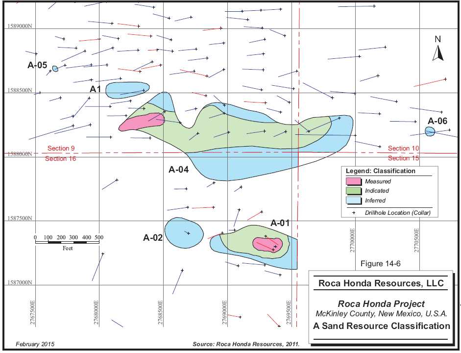
| Roca Honda Resources, LLC– Roca Honda Project, Project #2438 | |
| NI 43-101 Technical Report– February 27, 2015 | Page 14-21 |
| |
www.rpacan.com |
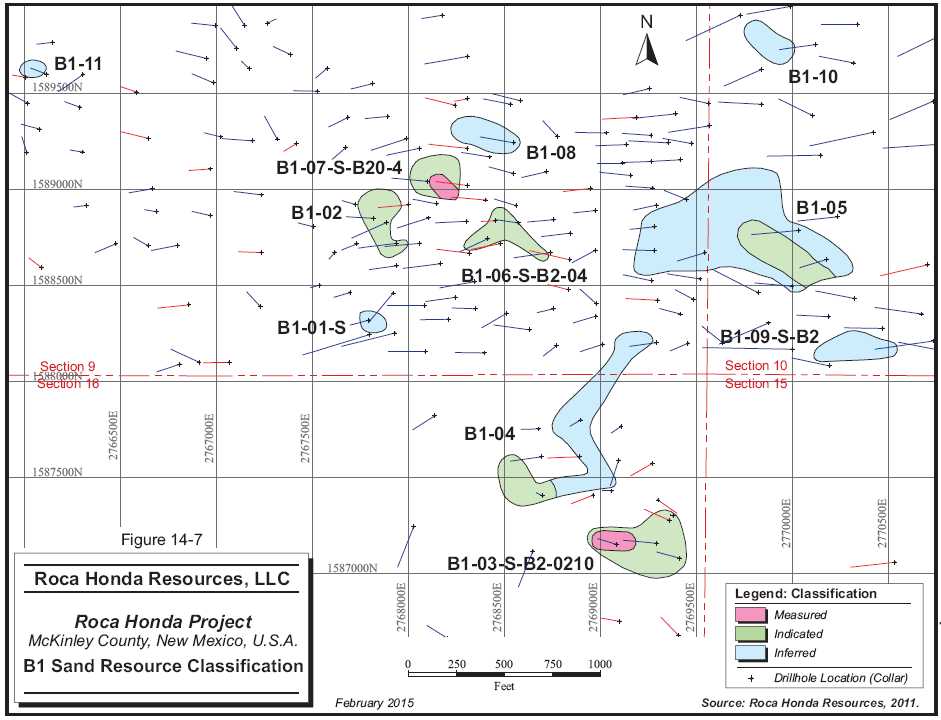
| Roca Honda Resources, LLC– Roca Honda Project, Project #2438 | |
| NI 43-101 Technical Report– February 27, 2015 | Page 14-22 |
| |
www.rpacan.com |

| Roca Honda Resources, LLC– Roca Honda Project, Project #2438 | |
| NI 43-101 Technical Report– February 27, 2015 | Page 14-23 |
| |
www.rpacan.com |

| Roca Honda Resources, LLC– Roca Honda Project, Project #2438 | |
| NI 43-101 Technical Report– February 27, 2015 | Page 14-24 |
| |
www.rpacan.com |

| Roca Honda Resources, LLC– Roca Honda Project, Project #2438 | |
| NI 43-101 Technical Report– February 27, 2015 | Page 14-25 |
| |
www.rpacan.com |
MINERAL RESOURCE ESTIMATE
The Roca Honda Mineral Resource estimate is summarized in Table 14-9 by domain at a 0.19% U3O8 cut-off grade.
Assumptions used in the determination of a 0.19% U3O8 cut-off grade are:
| • | Total operating cost (mining, G&A, processing) of US$241 per short ton; | |
| • | Royalty cost of 5% (only on Section 16); | |
| • | Process recovery of 95%; and | |
| • | Uranium price of US$65.00 per pound. |
The resource model and underlying data have not changed, however, RPA has reported Mineral Resources at a higher cut-off grade, consistent with the production scenario proposed in this PEA.
TABLE 14-9 MINERAL RESOURCE ESTIMATE AT – FEBRUARY 4, 2015
Roca Honda Resources LLC – Roca Honda Project
| 0.19% Cut-off U3O8 | Measured Resources | Indicated Resources | Inferred Resources | ||||||
| Mineralized Sand | Tons | % eU3O8 | lb U3O8 | Tons | % eU3O8 | lb U3O8 | Tons | % eU3O8 | lb U3O8 |
| Domain | (000) | (000) | (000) | (000) | (000) | (000) | |||
| A1_01 | 10 | 0.319 | 65 | 36 | 0.305 | 223 | 47 | 0.279 | 264 |
| A1_02 | 21 | 0.192 | 81 | ||||||
| A1_03 | 3 | 0.514 | 33 | 139 | 0.451 | 1,251 | 153 | 0.445 | 1,361 |
| A1_04 | 14 | 0.197 | 55 | ||||||
| A1_05 | |||||||||
| A1_06 | |||||||||
| A-Sand Subtotal | 13 | 0.365 | 98 | 175 | 0.420 | 1,474 | 235 | 0.374 | 1,761 |
| B1_01_S | |||||||||
| B1_02 | 15 | 0.305 | 91 | ||||||
| B1_03_S_01-02 | 14 | 0.193 | 53 | 41 | 0.257 | 211 | |||
| B1_04 | 0.000 | ||||||||
| B1_05 | 41 | 0.357 | 294 | 136 | 0.463 | 1,260 | |||
| B1_06_S_01-03 | 12 | 0.239 | 58 | ||||||
| B1_07_S_01 | 4 | 0.333 | 27 | 13 | 0.317 | 84 | |||
| B1_08 | 0.000 | ||||||||
| B1_09_S_01-02 | 13 | 0.537 | 140 | ||||||
| B1_10 | |||||||||
| B1_11 | |||||||||
| Roca Honda Resources, LLC– Roca Honda Project, Project #2438 | |
| NI 43-101 Technical Report– February 27, 2015 | Page 14-26 |
| |
www.rpacan.com |
| 0.19% Cut-off U3O8 | Measured Resources | Indicated Resources | Inferred Resources | ||||||
| Mineralized Sand | Tons | % eU3O8 | lb U3O8 | Tons | % eU3O8 | lb U3O8 | Tons | % eU3O8 | lb U3O8 |
| Domain | (000) | (000) | (000) | (000) | (000) | (000) | |||
| B1-Sand Subtotal | 4 | 0.332 | 27 | 122 | 0.301 | 737 | 149 | 0.469 | 1,400 |
| B2_01 | 14 | 0.322 | 92 | 37 | 0.334 | 245 | |||
| B2_02 | 21 | 0.294 | 121 | 61 | 0.283 | 343 | 29 | 0.256 | 147 |
| B2_03 | 59 | 0.261 | 310 | ||||||
| B2_04 | 52 | 0.483 | 506 | 281 | 0.446 | 2,504 | |||
| B2_07 | 0.124 | 0.232 | 0.577 | ||||||
| B2_05 | 5 | 0.716 | 69 | 11 | 0.745 | 167 | 14 | 0.589 | 168 |
| B2_06 | 13 | 0.266 | 70 | 3 | 0.242 | 15 | |||
| B2_08 | |||||||||
| B2_09 | |||||||||
| B2_10 | 2 | 0.395 | 17 | ||||||
| B2-Sand Subtotal | 91 | 0.421 | 766 | 370 | 0.422 | 3,120 | 141 | 0.314 | 887 |
| C1_01 | 68 | 0.551 | 748 | 416 | 0.611 | 5,078 | 249 | 0.419 | 2,084 |
| C1_02 | 6 | 0.282 | 33 | 4 | 0.282 | 22 | 29 | 0.273 | 160 |
| C1_03 | 80 | 0.765 | 1,217 | 94 | 0.771 | 1,452 | |||
| C1_04 | 18 | 0.752 | 272 | 45 | 0.583 | 525 | 124 | 0.904 | 2,243 |
| C1_05 | |||||||||
| C2_02_S_C1 | |||||||||
| C2_01_S_C1 | |||||||||
| C2_03 | |||||||||
| C-Sand Subtotal | 92 | 0.574 | 1,053 | 544 | 0.629 | 6,842 | 496 | 0.598 | 5,939 |
| D1_01-02 | 8 | 0.259 | 40. | 32 | 0.229 | 149 | 169 | 0.353 | 1,192 |
| D1_03 | 25 | 0.229 | 117 | ||||||
| D1_04 | 8 | 0.196 | 32 | 7 | 0.193 | 27 | |||
| D1_05 | 26 | 0.213 | 110 | ||||||
| D-Sand Subtotal | 8 | 0.259 | 40 | 92 | 0.222 | 407 | 176 | 0.347 | 1,219 |
| SW Deposit Total | 108 | 0.411 | 890 | 667 | 0.399 | 5,331 | 526 | 0.385 | 4,048 |
| NE Deposit Total | 100 | 0.549 | 1,093 | 636 | 0.570 | 7,250 | 672 | 0.533 | 7,158 |
| Grand Total | 208 | 0.477 | 1,984 | 1,303 | 0.483 | 12,580 | 1,198 | 0.468 | 11,206 |
Notes:
| 1. |
CIM definitions were followed for Mineral Resources. | |
| 2. |
Mineral Resources are estimated using a cut-off grade of 0.19% U3O8. | |
| 3. |
A minimum mining thickness of six feet was used, along with $241/ton operating cost and $65/lb U3O8 cut-off grade and 95% recovery. | |
| 4. |
Mineral Resources that are not Mineral Reserves do not have demonstrated economic viability. | |
| 5. |
Numbers may not add due to rounding. |
Figure 14-11 shows the sensitivity of the grade model results to cut-off grade
| Roca Honda Resources, LLC– Roca Honda Project, Project #2438 | |
| NI 43-101 Technical Report– February 27, 2015 | Page 14-27 |
| |
www.rpacan.com |
FIGURE 14-11 ROCA HONDA RESOURCE GRADE VS. TONS
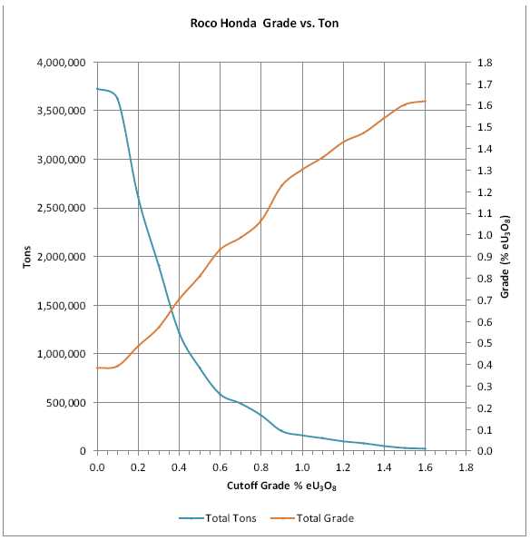
| Roca Honda Resources, LLC– Roca Honda Project, Project #2438 | |
| NI 43-101 Technical Report– February 27, 2015 | Page 14-28 |
| |
www.rpacan.com |
15 MINERAL RESERVE ESTIMATE
There are no current Mineral Reserves for the Roca Honda property.
| Roca Honda Resources, LLC– Roca Honda Project, Project #2438 | |
| NI 43-101 Technical Report– February 27, 2015 | Page 15-1 |
| |
www.rpacan.com |
16 MINING METHODS
The majority of the Mineral Resources of the Roca Honda deposit are located approximately 2,200 ft below the surface, directly beneath gently sloping washes and a mesa. The mineralization exists in the A, B, C, and D Sandstone units of the Westwater Canyon Member of the Morrison Formation in Sections 9, 10, 11, and 16. The deposit will be mined with a combination of step room-and-pillar (SRP) and drift-and-fill (DF) mining methods. Open pit mining was not considered due to the lack of economic grade mineralization near surface and the large magnitude of the surface disturbance that would be required. Any significant land disturbance associated with open pit mining was also considered to be a major impediment to obtaining permits.
The deposit will be accessed by a 2,100 ft shaft collared in Section 16, located approximately five miles west of the historic Mount Taylor mine. Mining is planned to access the higher grade resources at the base of the deposit and to minimize the surface disturbance. Ground conditions are expected to be fair to poor and primary stopes are expected to be stable at widths of 10 ft to 15 ft. Due to the high value of the resources in Section 10, and to maximize extraction, the use of high strength backfill is proposed. Mining will be done with a first pass of primary stopes followed by pillar extraction after the primary stopes have been backfilled.
The production plan is predicated on the mineralized material being processed at the White Mesa Mill. The yellowcake product will be sold and trucked off-site for further refining by other parties. RHR will be paid for the sale of the yellowcake produced at the White Mesa Mill. The layouts of the proposed mine and mill sites are shown in Figures 16-1 and 16-2, respectively.
RPA did not update the mine design and production schedule, which was developed using a cutoff grade of 0.13% U3O8. The previous work (2012 PEA) was reviewed, and it was determined that stopes remain above the updated cut-off grade of 0.19% U3O8. Some material below 0.19% U3O8 is included within the stope designs, and should be considered incremental material.
| Roca Honda Resources, LLC– Roca Honda Project, Project #2438 | |
| NI 43-101 Technical Report– February 27, 2015 | Page 16-1 |
| |
www.rpacan.com |
MINING OPERATIONS
The mining operation is designed on the basis of an average 1,085 stpd operation with a nine year mine life. The milling operation is designed for 2,000 stpd operation.
MINING METHOD
Mineral Resources are based on an underground mine design and stope schedule. The Westwater Canyon Member (Westwater) of the Morrison Formation, which hosts the mineralized horizons, is comprised primarily of sandstones with interbedded shales and mudstones. The A and B mineralized horizons (Sections 9/16) are located in the upper area of the Westwater. The C and D mineralized horizons (Section 10) are located in the lower portion of the Westwater. The Recapture Zone is located immediately below the Westwater Canyon member. Due to historical significant difficulties in both developing and maintaining the integrity of drifts in the Recapture Zone, the mine design avoids any excavations in this Zone.
In Sections 9/16, the mineralized horizons will be defined using longhole drills from a dedicated drilling horizon located below the mineralized zones. In Section 10, the mineralized horizons will be defined using longhole drills on a stope by stope basis.
The transition grade was calculated at 0.265% U3O8. Stopes with average diluted grades of less than 0.265% U3O8 will be mined using the SRP method. Stopes with average diluted grades greater than 0.265% U3O8 will be mined using the DF method. With the SRP method, permanent pillars will be left in a pre-designed pattern and low-strength cemented rockfill (CRF) will be placed in mined-out areas as backfill. For the DF method, a high-strength CRF will be placed in the mined-out areas. The minimum thickness used in the development of the Mineral Resource estimate was six feet. The mineralized zones range in thickness from 6 ft to 21 ft. Mineralized zones with thicknesses from 6 ft to 12 ft will be mined in one pass. Mineralized zones exceeding 12 ft in thickness will be mined in two sequential overhand cuts with each cut being approximately one half of the overall zone thickness.
The Life of Mine (LoM) schedule was developed on the basis of initiating development from the production shaft located in Section 16. The mining areas in Sections 9/16 will be connected to Section 10 by means of a 3,600 ft double decline haulageway. Primary development connecting the shaft to the various mineralized zones (including the double decline) will be driven 10 ft wide by 12 ft high. Stope access development connecting the primary development to the individual stopes will be driven 10 ft wide by 10 ft high.
| Roca Honda Resources, LLC– Roca Honda Project, Project #2438 | |
| NI 43-101 Technical Report– February 27, 2015 | Page 16-2 |
| |
www.rpacan.com |
The mining sequence in each Section is dependent upon the development schedule but, in general, is sequenced to prioritize the mining of the largest and highest grade zones in each section of the mine. There is also a requirement to sequence the mining of any stacked ore zones from top down.
Stope mining begins approximately four years after the start of construction and the operating mine life spans nine years. The production rate averages approximately 900 st per milling-day during the time that mining occurs in Sections 9 and 16 only, increases to 1,040 st per milling-day when Sections 9, 16, and 10 are mined simultaneously, and drops to 800 st per milling-day when mining from Section 10 only.
Depressurization of the three, main aquifers in the Project area will be accomplished by the use of 19 depressurization wells and underground long holes that will supply water to eleven underground pumping stations that will ultimately feed water to the Section 16 shaft sump pumps and three discharge pump stations located in the shaft. It has been estimated that the mine will discharge a nominal 2,500 US gallons per minute (gpm) of water at temperatures between 90ºF and 95ºF. An additional 2,000 gpm will be produced by surface wells and therefore the total discharge rate could be as high as 4,500 gpm.
The deposit will be developed and mined on the basis of single-pass ventilation using a series of separate and independent intake and exhaust networks. The design requires a total of five exhaust ventilation raises (three in Section 9 and two in Section 10) as well as an intake ventilation raise in Section 10. Two of the ventilation raises, one in Section 16 and one in Section 10, will be equipped with emergency evacuation hoisting equipment. Midway through the mine life, one of the raises in Section 9 will be converted from exhaust to intake.
The LoM statistics for the Roca Honda Project are summarized in Table 16-1.
| Roca Honda Resources, LLC– Roca Honda Project, Project #2438 | |
| NI 43-101 Technical Report– February 27, 2015 | Page 16-3 |
| |
www.rpacan.com |
TABLE 16-1 KEY LIFE OF MINE PRODUCTION STATISTICS
Roca Honda Resources LLC – Roca Honda Project
| Life of Mine | ||
| Metric Area | Units | Quantity |
| Development - Primary (feet) | 000 ft | 15.2 |
| Development - Stope Access (feet) | 000 ft | 109.5 |
| Stope Mining - SRP (tons) | 000 t | 1,166.9 |
| Stope Mining - DF (tons) | 000 t | 2,060.9 |
| Production (tons) | 000 t | 3,417.3 |
| Backfill from Underground Development - SRP (tons) | 000 t | 386.1 |
| Backfill from Surface Stockpile - SRP (tons) | 000 t | 49.2 |
| Backfill from Surface Quarry - SRP (tons) | 000 t | 147.3 |
| Backfill from Surface Stockpile - DF (tons) | 000 t | 463.6 |
| Backfill from Surface Quarry - DF (tons) | 000 t | 1,185.2 |
| Definition Drilling (feet) | 000 ft | 2,875.0 |
Note: For production only; does not include costs incurred during development.
| Roca Honda Resources, LLC– Roca Honda Project, Project #2438 | |
| NI 43-101 Technical Report– February 27, 2015 | Page 16-4 |
| |
www.rpacan.com |

| Roca Honda Resources, LLC– Roca Honda Project, Project #2438 | |
| NI 43-101 Technical Report– February 27, 2015 | Page 16-5 |
| |
www.rpacan.com |

| Roca Honda Resources, LLC– Roca Honda Project, Project #2438 | |
| NI 43-101 Technical Report– February 27, 2015 | Page 16-6 |
| |
www.rpacan.com |
MINERALIZED MATERIAL TRANSPORTATION
The mining will be done with rubber-tired mechanized equipment to provide operational flexibility. Broken mineralized material will be hauled and deposited in an ore pass leading to a skip pocket chamber. At each of the two, skip loading pockets, located on either the 5340 or 5260 shaft stations, 15 in. fine mineralized material will be stored in a 650 ton storage area. From the shaft stations, the mineralized material will be transported to surface by a vertical shaft double drum hoist. Shaft highlights are:
| • | Finished Diameter: 18 ft | |
| • | Concrete lining: 1 ft | |
| • | Type of Hoist: Clutched Double Drum, 8 ft diameter | |
| • | Size of Rope(s): 1.5 in. | |
| • | Height of Headframe: 80 ft | |
| • | Headframe Type: Structural Steel with Backlegs | |
| • | Size of Skips: Two, 6.5 ft by 5.5 ft | |
| • | Hoist Capacity: 1,250 ton/8 hr shift | |
| • | Skip Capacity: 10 tons | |
| • | Man Cage Capacity: 12 miners; | |
| • | Emergency Hoist Capacity: 12 miners; | |
| • | Emergency Hoist Power: 600 hp | |
| • | Hoist power: 1,000 hp | |
| • | Collar Elevation: 7,240 fasl | |
| • | Sump Elevation: 5,140 fasl | |
| • | Shaft depth: 2,100 ft | |
| • | Primary production levels: 5,340 fasl, 5,260 fasl | |
| • | Booster pumping stations: 5,260 fasl, 5,945 fasl, 6,545 fasl | |
| • | Stratigraphy: Mancos Shale and Jurassic Morrison Formation, especially Westwater | |
| • | Aquifers: Gallup, Dakota and Westwater | |
| • | Schedule: Approximately 925 days for construction |
Once the mineralized material is hoisted to the surface, it will be transferred into highway trucks, which will deliver the material to the White Mesa Mill.
| Roca Honda Resources, LLC– Roca Honda Project, Project #2438 | |
| NI 43-101 Technical Report– February 27, 2015 | Page 16-7 |
| |
www.rpacan.com |
MINE DESIGN
The key design criteria for the Roca Honda Project were:
| • | Mine capacity up to 1,200 stpd and process plant capacity up to 2,000 stpd (700,000 stpa) | |
| • | 227,000 st in year one, approximately 400,000 stpa thereafter | |
| • | Nine-year mine life | |
| • | Mine production from Sections 9, 16 and 10, plus a small part from Section 11 | |
| • | Mechanized mining | |
| • | Double-drum shaft hoisting of mineralized material to the surface and highway truck haulage to the White Mesa Mill | |
| • | Backfill, where needed for maximum extraction |
RPA recommends the use of medium-sized mechanized equipment suitable for headings of 100 ft2 to 150 ft2. Mechanized equipment will be selected to minimize employee exposure to working areas.
The mine plan was developed by RPA and reviewed by RHR. The stoping plan starts in the highest grade areas of Sections 9 and 16, and then proceeds to Section 10. The stoping is planned in a series of primary and secondary stopes.
Mining methods considered included the following constraints:
| • |
Open stope areas will require stable back conditions during extraction. Back stability will need to consider rock strength, and proximity and condition of recent workings and groundwater drainage conditions. | |
| • | Blocks of ground serving as temporary or permanent pillars must remain stable during extraction of adjacent ground. | |
| • | Backfilling of primary openings needs to provide sufficient back support to allow secondary pillars to be mined with a stable back. | |
| • | Backfill from primary openings should not slough into rib pillar cross-cuts during extraction. | |
| • |
Backfill operations will require tight filling against supported rock including pillar ribs and stope backs by up-dip filling operations. In multi-cut areas that require working from fill, the working mat surface should be sufficiently competent to support equipment. | |
| • | Temporary access ramps should remain stable during their expected life and can be re- cut provided roof and rib stability can be maintained. |
| Roca Honda Resources, LLC– Roca Honda Project, Project #2438 | |
| NI 43-101 Technical Report– February 27, 2015 | Page 16-8 |
| |
www.rpacan.com |
| • | Backfilling operations should include water management provisions to control drainage to main haulages. | |
| • | Mineralized lenses can be stacked one above the other with as little as tens of feet of separation. | |
| • | Considerations should be made in each mining area for variations in mining-induced stresses, rock failure mechanisms, and local ground deformations. |
Stopes were designed with flat footwalls and were oriented in each of the three areas to maximize the mineralized extraction and minimize dilution due to the variations in the footwall of the Section 10. Stopes will be accessed through a system of ramps located outside the Mineral Resources in Sections 9, 16, and 10, plus a small part in Section 11. The locations of the ramps are shown in Figures 16-3 through 16-5. The access ramps will connect to a haulage drift and also to ventilation raises to the surface. For each stope, a short stope access will be driven to the first cut and then slashed to access subsequent cuts above or below the initial cut.
Mine ventilation will be achieved with surface fans located at exhaust raise locations. Fresh air will enter the mine via the Section 16 production shaft or an intake ventilation raise. Fresh air will travel through primary haulage ways to active mining areas. Fresh air will then enter active stopes via the fresh air stope access drift, pass through the stope and finally exit the stope where the air will be directed toward a one pass only ventilation exhaust raise.
Room-and-pillar mining is a simple, low-capital cost mining method where 70% to 90% recovery can be expected dependent upon the rock strengths and geological structures encountered. Although pillars are anticipated to remain unmined, even with tight backfilling and artificial support, the method is sufficiently flexible to achieve required production rates, control cut-off grades, and maintain safe working conditions. The operational sequence must be modified when mining heights are high (>12 ft) since multi-cuts and stacked pillars (low width-to-height ratios) are required and backfilling must be used to ensure pillar stability. This method becomes a hybrid of the cut-and-fill method in areas where the mineralization is thick (12 ft to 21 ft high) because slender pillars are ineffective for roof support and strong global backfill support must enhance local roof support.
Drift-and-fill methods are well suited for selective precision mining in variable-grade areas and are quite flexible resulting in high extraction ratios. The volume of open ground at any one time is small since drifts are mined and immediately backfilled before adjacent drifts are mined. The development can be placed in the mineralized areas, minimizing waste rock. This method is not well suited for high production rates, unless many stopes are simultaneously opened, which requires a laterally extensive mineralized zone. The cost of local support (roof cabling through multi-cuts) is high because all cuts must be fully supported. This method would be considered in variable high-grade areas, where maximum recovery is desired.
| Roca Honda Resources, LLC– Roca Honda Project, Project #2438 | |
| NI 43-101 Technical Report– February 27, 2015 | Page 16-9 |
| |
www.rpacan.com |
Open stoping, longhole panel mining is considered a “quasi-precision” underground mining method that can be managed through blasthole loading. High-tonnage production rates can be obtained with a limited number of active stopes and flexible stope layouts accommodate variable mineralized grades. Open stoping is not considered an attractive method here because anticipated roof strengths and stand-up times are too low and support costs could be excessive.
Shortwall and longwall mining methods are capital intensive and are inflexible with steep dips (>8° to 10°) and fault throws. These fixed-dimension methods are unattractive for the mineralization at the Roca Honda Project because of mineable grade variations and the non-tabular shape, which require variable mining configurations. Wall lengths would not be long enough to justify capital and move costs.
Block cave methods are frequently used in massive deposits, especially when the mineralized material is vertically extensive, because extraction is primarily gravity driven. This is not an attractive method in this type of deposit because of the limited vertical extent, need to minimize overburden disturbance (aquifers and at surface), and tonnage is insufficient to justify initial capital cost.
Sublevel caving is similar to block caving, but it can be implemented over smaller volumes. This method works well in steeply dipping tabular deposits since it affords greater grade control and less capital than block cave methods. The method is not amenable for the Roca Honda Project for the same reasons as block caving is not attractive.
Open pit mining is not recommended due to the 2,000 ft depth of the mineralized material body. The cost of waste removal would be excessive.
In summary, these trend-type mineralized deposits will be developed and mined by two modified room-and-pillar methods using ground support during development to ensure roof stability, especially in weak ground conditions.
| Roca Honda Resources, LLC– Roca Honda Project, Project #2438 | |
| NI 43-101 Technical Report– February 27, 2015 | Page 16-10 |
| |
www.rpacan.com |
With the wide range of mineralized zone thicknesses (from 6 ft to 21 ft) and dips/plunges (from flat to 15°), one of the mining methods selected for Roca Honda is SRP incorporating moderate strength cemented rock fill. This method allows for mobile equipment to be used effectively in the range of dips/plunges encountered at Roca Honda. This method is being recommended for the lower grade mineralized lenses.
DF mining is also recommended for the higher grade mineralized lenses. This method is widely used in other mines with similar ground conditions and will result in higher mining recoveries as the need to leave permanent pillars will be significantly reduced. This method, however, requires a high quality, high strength engineered backfill in order to be successful.
Bulk mining methods were investigated, particularly for the thick (up to 20 ft) zones. One method considered involved mining of the thick zones in staggered primary and secondary panels using engineered cemented backfill. This method was not considered to be applicable due to the weak rock conditions. The low rock strengths and limited stand-up time made this method impractical given the relatively high stope walls, which would be exposed during the benching process.
MINING RECOVERY AND DILUTION
The deposit is relatively flat-lying and will be mined using both SRP stoping in the lower grade zones and DF stoping in the higher grade sections. Dilution is estimated to average 17.1% at a grade of 0.030% U3O8. This relationship includes both low grade and waste material dilution estimates are based on one foot of overbreak in the roof and six inches in the floor of all single lift stopes. In the case of multi-lift stopes, the initial cuts include only six inches of floor dilution. The final cut includes both floor dilution and roof dilution.
To arrive at the Mineral Resources that are potentially mineable in this PEA, RPA used a diluted cut-off grade of 0.110% U3O8, a minimum mining thickness of six feet, and an average calculated mining recovery of 88%. The resource model and underlying data have not changed, however, RPA has reported Mineral Resources at a higher cut-off grade, consistent with the production scenario proposed in this PEA.
SHAFT PILLAR CONSIDERATIONS
| • | The shaft should be located as near to the centroid of the mineralized structures as possible to minimize haulage distances . |
| Roca Honda Resources, LLC– Roca Honda Project, Project #2438 | |
| NI 43-101 Technical Report– February 27, 2015 | Page 16-11 |
| |
www.rpacan.com |
| • | The shaft should not penetrate the Recapture mudstone formation to any appreciable extent to avoid swelling and closure problems when distressed and wet. | |
| • | The shaft should be located at least 400 ft from the major northeast-southwest fault system to minimize the potential for mining-induced stress displacements . | |
| • |
The shaft should be at least 350 ft from any high extraction mining so as to avoid having mineralized material tied up in shaft pillar and mining-induced subsidence differential displacements impacting stability of the shaft liner and hoist guide alignment. |
GEOTECHNICAL ANALYSIS
The estimated geotechnical conditions determined the mine design parameters. These parameters included support for open spans in both long-term haulages and in short-term drifts within a stope. The support requirements were then used to estimate the cost for ground support.
The approach adopted considers that the empirical methods used for making estimates of the support parameters are based on similar case histories in a range of applicable ground conditions. The use of empirical methods have been shown to be a reasonable approach to assessing ground support as long as anticipated ground conditions are within the data range. Although rock mass strengths at Roca Honda are considered poor to average quality, their Rock Mass Rating (RMR) values are within the data range of the empirical methods.
No analyses beyond these empirical assessments were performed to check the recommended support parameters. Such analyses will be warranted when additional site specific data from underground are available and where analyses might include numerical modelling.
To account for the anticipated variability in rock quality a range of rock mass strengths were considered. For this reason, a range of three anticipated ground conditions were defined: weak, medium, and strong. For each of these we have estimated the percentage of excavations that will be in each ground condition, and thus the type of support required for the type of opening (long-term primary, stope access development, and short-term stope drifts.
The groundwater table is estimated to be at a depth of 886 ft at the Section 16 proposed shaft location (elevation of 6,378 ft amsl, where the ground elevation is 7,264 ft amsl).
DEVELOPMENT AREAS
Stability of open spans in a blocky rock mass is anticipated to be governed by the thickness of bedding in the roof and intersection of joints producing massive sandstone blocks that may be removable into the opening. Stability was analyzed using a simple limit equilibrium method that balanced block loads and support loads. The analysis used the following assumptions.
| Roca Honda Resources, LLC– Roca Honda Project, Project #2438 | |
| NI 43-101 Technical Report– February 27, 2015 | Page 16-12 |
| |
www.rpacan.com |
| • | Drift width = 10 ft | |
| • | Unit weight of roof rock = 145 lb/ft3 | |
| • | Max bedding slab thickness = 50% of room width | |
| • | Minimum shear strength of roof rock = 350 psi |
The minimum safety factor for bolts is 1.50. The bolts were assumed to be 45 ksi yield steel.
| Roca Honda Resources, LLC– Roca Honda Project, Project #2438 | |
| NI 43-101 Technical Report– February 27, 2015 | Page 16-13 |
| |
www.rpacan.com |

| Roca Honda Resources, LLC– Roca Honda Project, Project #2438 | |
| NI 43-101 Technical Report– February 27, 2015 | Page 16-14 |
| |
www.rpacan.com |

| Roca Honda Resources, LLC– Roca Honda Project, Project #2438 | |
| NI 43-101 Technical Report– February 27, 2015 | Page 16-15 |
| |
www.rpacan.com |

| Roca Honda Resources, LLC– Roca Honda Project, Project #2438 | |
| NI 43-101 Technical Report– February 27, 2015 | Page 16-16 |
| |
www.rpacan.com |

| Roca Honda Resources, LLC– Roca Honda Project, Project #2438 | |
| NI 43-101 Technical Report– February 27, 2015 | Page 16-17 |
| |
www.rpacan.com |
![]()
| Roca Honda Resources, LLC– Roca Honda Project, Project #2438 | |
| NI 43-101 Technical Report– February 27, 2015 | Page 16-18 |
| |
www.rpacan.com |
UNDERGROUND LAYOUT
MINE DEVELOPMENT
Primary level development will be excavated 12 ft high by 10 ft wide incorporating a semi-circular arched back in the upper 3 ft of the heading. This heading size was selected as the best compromise between the need to minimize the drift excavation dimensions and span due to the relatively weak rock conditions, yet be sufficiently large to allow adequate clearance for suitably sized mobile equipment and the associated piping, electrical and communications cables, services and, most importantly, the 36 in. diameter rigid ventilation ducting. This heading size was also selected as these drifts will be the primary ventilation routes for both intake and exhaust air, most importantly between the production shaft in Section 16 and the Northeast mineralized zone workings.
It is expected that the weak sandstones and shales will degrade from vehicular traffic. The use of roadbase material will therefore be necessary. Roadbeds will be constructed by placing a “Tensar” mesh mat on the floor of the drift to prevent mixing of the weak floor material and the roadbed material. A six-inch layer of screened rock will be placed on the mesh mat. All roads will be ditched and crowned.
The 3,600 ft decline connecting the Southwest and Northeast mineralized zones has been designed as a double heading. This is required for ventilation purposes, both during the driving of the decline as the need for booster fans is eliminated, and for subsequent mining in the Northeast. When completed, one of the decline headings will serve as a dedicated fresh airway connecting the Northeast workings to the Section 16 production shaft fresh air intake. The other decline heading will serve as a dedicated exhaust airway, connecting to the various exhaust boreholes in the Southwest mining area, thus supplementing the exhaust capacity of the boreholes in the Northeast area. Depressurizing of the water in the decline area will precede the initiation of the decline construction, and it will be maintained after completion.
Development productivity calculations were prepared to estimate the rate of advance and the manpower and equipment requirements for the development work. The productivity was developed from first principles with each part of the development cycle time estimated to generate the overall cycle time for development headings.
In all cases, the mucking was assumed to be to a muck bay with re-mucking as a separate activity such that the face could be turned around as rapidly as possible. Truck loading and hauling are considered to be activities that can be undertaken simultaneously with the other activities at the face.
| Roca Honda Resources, LLC– Roca Honda Project, Project #2438 | |
| NI 43-101 Technical Report– February 27, 2015 | Page 16-19 |
| |
www.rpacan.com |
Over the course of the mine life, a total of 31,564 ft of primary development is scheduled to be excavated. Of this total, 19,799 ft (62.7%) will be driven single face incline and 4,630 ft (14.7%) will be driven single face decline. In addition, 7,135 ft (22.6%) will be driven multi-face decline. The latter relates to the double-decline ramp connecting Sections 9/16 to Section 10.
UNDERGROUND MOBILE EQUIPMENT
A fleet of mobile equipment, suitable for the proposed heading sizes and mining methods, has been selected and quantified. Budget quotes were obtained from equipment suppliers for the production equipment. Service equipment cost estimates were obtained from other recent RPA studies. Equipment needs for development and stoping are almost identical and, as development requirements diminish over time, the equipment is transferred to stoping. This eliminates the need to procure additional mobile equipment as the number of active stopes increases. Mobile equipment requirements are shown in Table 16-2.
TABLE 16-2 MINE EQUIPMENT SUMMARY
Roca Honda
Resources LLC – Roca Honda Project
| Mobile Equipment | hp | Quantity | Total hp |
| Jumbo - 1 boom (development) | 80 | 4 | 320 |
| LHD 3-yd (development) | 130 | 4 | 520 |
| Materials Handler with man-basket (development) | 101 | 2 | 202 |
| Roofbolter (development) | 80 | 4 | 320 |
| Shotcreter (development) | 148 | 2 | 296 |
| Remix Transporter (development) | 200 | 2 | 400 |
| Jumbo - 1 boom (stoping) | 80 | 5 | 400 |
| LHD 1.75-yd (stoping) | 75 | 3 | 225 |
| LHD 3-yd (stoping) | 130 | 2 | 260 |
| Roofbolter (stoping) | 80 | 5 | 400 |
| LHD 1.75-yd Backfill Rammer (stoping) | 75 | 2 | 150 |
| LHD 3-yd Backfill Rammer (stoping) | 130 | 2 | 260 |
| Materials Handler with man-basket (stoping) | 101 | 3 | 303 |
| Truck 16-ton ejector box (development and stoping) | 210 | 8 | 1,680 |
| LHD 3 yd (shaft station transfer to skip pocket) | 130 | 2 | 260 |
| Jumbo - 1 boom (spare) | 80 | 1 | 80 |
| LHD 3-yd (spare) | 130 | 1 | 130 |
| Roca Honda Resources, LLC– Roca Honda Project, Project #2438 | |
| NI 43-101 Technical Report– February 27, 2015 | Page 16-20 |
| |
www.rpacan.com |
| Mobile Equipment | hp | Quantity | Total hp |
| LHD 1.75-yd Backfill Rammer (spare) | 75 | 1 | 75 |
| LHD 3-yd Backfill Rammer (spare) | 130 | 1 | 130 |
| Roofbolter (spare) | 80 | 1 | 80 |
| Truck 16 ton ejector box (spare) | 210 | 1 | 210 |
| U/G Longhole Drill | 73 | 2 | 146 |
| Materials Handler with boom | 101 | 2 | 202 |
| Boom Truck | 148 | 2 | 296 |
| Caterpillar 272C | 90 | 2 | 180 |
| Maintenance Utility Vehicle | 148 | 2 | 296 |
| Pump Crew Utility Vehicle | 148 | 1 | 148 |
| Electrical Utility Vehicle | 74 | 2 | 148 |
| Supervision and General Utility Vehicle | 22 | 3 | 66 |
| Engineering/Geology Utility Vehicle | 22 | 3 | 66 |
| Surveyor Utility Vehicle | 74 | 1 | 74 |
| Personnel Transport Vehicle | 148 | 2 | 296 |
| Grader | 110 | 1 | 110 |
| Total Mobile Equipment | 79 | 8,729 |
The Load Haul Dumps (LHDs), trucks, and jumbos will be required for the mine development and will be utilized by contractors for the pre-production period. In operations, these units are expected to experience relatively low utilization, but the fleet size is considered necessary to provide the back-up for this remote site operation.
Equipment will be selected based upon price and support and it is planned to purchase as many units as possible from one supplier to minimize the number of suppliers and to increase the level of common spares.
MINE INFRASTRUCTURE
UNDERGROUND CONVEYANCE
Historically, the size of the mineralized material supplied from the mine to the process plant has not required a crushing circuit. Mineralized material will be dumped into a single dump point feeding the ore pass. The dump will be equipped with a grizzly and rock breaker.
| Roca Honda Resources, LLC– Roca Honda Project, Project #2438 | |
| NI 43-101 Technical Report– February 27, 2015 | Page 16-21 |
| |
www.rpacan.com |
SPACE REQUIREMENTS
Space requirements for the mine were determined based on the staffing requirements, production rate, type of mining method, and equipment. The mine surface requirements are summarized in Table 16-3.
TABLE 16-3 MINE SURFACE INFRASTRUCTURE SPACE REQUIREMENTS –
BUILDINGS
Roca Honda Resources LLC – Roca Honda Project
| Area Description | Estimated Square | Comments | |
| Feet | |||
| Mine Dry and Office Building | 30,572 | 2 Floors | |
| Office and Dry | 19,528 | 1st & 2nd floor | |
| Maintenance and Shop | 8,160 | 1st & 2nd floor | |
| Indoor Warehouse | 4,080 | 1st & 2nd floor | |
| Emergency Services Building | 3,784 | ||
| Entrance, Guard Shack and Scale House | 1,542 | ||
| Assay Laboratory Building | 320 | Trailer | |
| Outdoor Warehouse | 9,800 | Cold Warehouse is in corner of yard | |
| Cold Warehouse (Not Insulated or heated) | 3,200 | ||
| Explosives Magazine No 1 | 160 | ||
| Detonators, Caps and Fuse Magazine No. 2 | 36 | ||
| Tank Farm Containment Area | 800 | 20,000 gal | |
| Batch Plant Area | 900 | ||
| Stockpile (At the headframe) | 2,500 | ||
| Waste Stockpile (At the headframe) | 2,500 | ||
ELECTRICAL DISTRIBUTION
Electrical power will be supplied by existing power lines that transverse the Project mine area. Backup generated power will be supplied by a 5 MW diesel power station located at the site. The power will be generated and distributed about the site at 600 V and 4,160 V. The feed to the mine will be by 4,160 V power cables installed in the decline feeding load centers with 4,160:600 V transformers. Whenthe ventilation raise is in place an additional line may be installed in the raise to provide a loop for power distribution. As an alternative, bore holes may be used as conduit for power lines to the underground mine to provide multiple feeds and to reduce the line loss with the shorter supply cables.
Electrical power will be required at the mobile load centers to provide power for jumbos and fans in the development and production areas. An electrical power supply to the main surface fan locations will also be required.
| Roca Honda Resources, LLC– Roca Honda Project, Project #2438 | |
| NI 43-101 Technical Report– February 27, 2015 | Page 16-22 |
| |
www.rpacan.com |
A new transmission tap substation at or near Continental Divide Electric Cooperative’s existing Gulf Minerals substation would reduce the transmission level voltage to 25 kV for distribution to the mine site and water treatment plant. The distribution line will be run overhead on poles along existing right of way to the water treatment plant site. The existing cable is not sized properly for the expected load, so it would need to be upgraded. After the distribution line reaches the mine site the overhead distribution will be dropped off at one or more locations as required to service the mine, ventilation fans and de-watering wells.
Power distribution on the mine site includes: main shaft, de-watering pumps, ventilation shafts, and escape shafts. It will be distributed as 25 kV on overhead lines with taps and individual transformers for each location. The main shaft area will have two transformers. One will be 25 kV/4.16 kV to service the hoist and power for the mine. The other transformer will reduce the voltage from 4.16 kV/480 V for the other surface loads around the shaft.
The underground loads include some at 4.16 kV and the rest will be reduced to 480 V or 120/208 V for the other loads as required. All low voltage motors will be started and controlled through standard Motor Control Centers. Medium voltage (MV) motors will be started and controlled with their MV starters.
The site electrical utilization is three phase, 60 Hz, 480 V for all motors 200 hp or less, all motors larger than 200 hp will be 4,160 V. Surface grounding will be per National Electric Code (NEC) requirements and Institute of Electrical and Electronic Engineers (IEEE) 142 standards. Underground grounding will be per Mine Safety and Health Administration (MSHA) requirements.
UNDERGROUND POWER REQUIREMENTS
The estimated power consumption for the underground mining, including ventilation is 1.6 MW as shown in Table 16-4
| Roca Honda Resources, LLC– Roca Honda Project, Project #2438 | |
| NI 43-101 Technical Report– February 27, 2015 | Page 16-23 |
| |
www.rpacan.com |
TABLE 16-4 ESTIMATED ELECTRICAL LOAD – MINE ONLY
Roca Honda Resources LLC – Roca Honda Project
| Load Description | |||||
| Surface Plant - Main Hoist Area | No. | Unit hp | Connected | Load | Load hp |
| Units | hp | Factor | |||
| Main Hoist | 1 | 1,000 | 1,000 | 80% | 800 |
| Compressors | 2 | 150 | 300 | 67% | 201 |
| Surface Pumps | 1 | 700 | 700 | 90% | 621 |
| Heat Trace | 5 | 30 | 150 | 100% | 150 |
| Shop Equipment | 1 | 15 | 15 | 40% | 6 |
| Hot Water Heaters | 1 | 25 | 25 | 70% | 18 |
| Lighting | 1 | 15 | 15 | 90% | 14 |
| Office | 1 | 20 | 20 | 40% | 8 |
| Surface Plant - Ventilation Shaft Areas | |||||
| Primary Ventilation Fans | 3 | 150 | 450 | 65% | 294 |
| Lighting | 1 | 10 | 10 | 90% | 9 |
| Shops | 1 | 20 | 20 | 50% | 10 |
| Portable Welder | 1 | 25 | 25 | 80% | 20 |
| Underground | |||||
| Shaft Pumps | 8 | 250 | 2,000 | 40% | 800 |
| Pumps | 12 | 150 | 1,800 | 78% | 1,401 |
| Secondary Fans | 8 | 50 | 400 | 100% | 400 |
| Underground Shops | 2 | 100 | 200 | 23% | 46 |
| Longhole Drill | 1 | 75 | 75 | 43% | 32 |
| Backfill/Aggregate Mixing Plant | 2 | 100 | 200 | 12% | 24 |
| Cement Mixing Tank | 2 | 50 | 100 | 12% | 12 |
| Electrohydraulic Drill Jumbo | 8 | 75 | 600 | 24% | 144 |
| Rockbolter | 8 | 75 | 600 | 24% | 144 |
| Shotcreter | 1 | 75 | 75 | 24% | 18 |
| Lunch Rooms | 2 | 20 | 40 | 8% | 3 |
| Underground Lighting | 1 | 30 | 30 | 58% | 17 |
| Subtotals | 8,850 | 5,191 | |||
| Contingency | 10% | 10% | |||
| Total Connected Horsepower (hp) | 9,735 | ||||
| Total Load (hp) | 5,710 |
| Roca Honda Resources, LLC– Roca Honda Project, Project #2438 | |
| NI 43-101 Technical Report– February 27, 2015 | Page 16-24 |
| |
www.rpacan.com |
WATER TREATMENT PLANT POWER REQUIREMENTS
The Continental Divide Electric Cooperative 25 kV line that provides power to the mine will be extended to provide power for the Water Treatment Plant. At the plant site a 25 kV/480 V transformer will be used to supply power to a motor control center for distribution to the various low voltage loads. A 100 kW back-up power plant supplies emergency power to the water treatment plant.
VENTILATION
One of the major operating costs associated with underground mining is the electrical cost associated with operating a mine’s primary and auxiliary ventilation circuit. In this regard, RPA, in planning Roca Honda’s primary ventilation, has taken steps to minimize the impact that the raise boring development will have on the mine’s development and operating costs. The primary goal will be to maintain a sound work environment.
Roca Honda’s primary ventilation system consists of:
| • | A Production Shaft (Section 16 Shaft) | |
| • | Two (9 ft finished diameter) Emergency Egress Raises (Section 16-EE1 and Section 10- EE2) | |
| • | Four (9 ft finished diameter) Ventilation Raises (Section 16-V3, Section 16-V7, Section 10-V5 and Section 10-V6) |
The Section 16 Shaft will have an 18 ft finished inside diameter, in which two skips and a man cage will operate.
The two emergency egress raises, Section 16-EE1 and Section 10-EE2, will be a steel-lined, 9 ft finished diameter raise with rope guides for the egress capsule. The egress capsule will be located outside the raise in either the respective emergency egress hoists’ head frames, or immediately below the raise, on the 5260 Level or the 4665 Level, which will reduce impeding airflow.
The remaining ventilation raises, Section 16-V3 through Section 16-V7, are exhaust raises. They are also 9 ft diameter steel-lined raises. While the steel-lining was initially installed for ground control issues, the lining system also appreciably reduces the system’s air resistance.
| Roca Honda Resources, LLC– Roca Honda Project, Project #2438 | |
| NI 43-101 Technical Report– February 27, 2015 | Page 16-25 |
| |
www.rpacan.com |
It is assumed that the presence of radon and thoron gas from the rock will not be an issue with the correct installation of the proposed ventilation system, and that these contaminants will be appropriately diluted and exhausted with the mine air. Procedures for closing unused areas and for checking areas prior to reopening unventilated areas will be established to ensure that areas are suitably ventilated and that there are no noxious gases present before work commences in a new area or an area, which has been closed for some time.
The mine ventilation air flow was based upon the mine equipment fleet with an estimate of equipment utilization and an additional allowance for losses and additional needs, and the dilution of any deleterious gases such as radon. The mine ventilation requirements, per mining phase, vary from 35,000 cfm during shaft sinking to approximately 1,200,000 cfm at the end of the mine life.
MINE AIR HEATING INTAKE
In light of the sub-zero temperatures at or near the surface and the need to prevent freezing of water lines and ice buildup, the mine air will be heated using direct fired mine air heaters located at the mine air intake. The coldest mean monthly low temperature on record at nearby weather stations was14.4 oF. In sizing the Section 16 Shaft Heating Plant, RPA utilized a 30oF temperature rise to determine the plant’s maximum heating capacity. The mine area heating requirements should be minimal, because of the rock temperatures of the mine. The main shaft will be an intake shaft for ventilation; therefore, cold air will be drawn into the mine at this point.
DEWATERING
The mine is expected to be a “wet” mine and groundwater inflows are expected to be moderate to high with a maximum estimated 2,500 gpm of groundwater inflow initially into the mine. The estimate of groundwater inflow has been based upon the observations of the numerous core drill programs and observations from historical mine and public reports previously developed in the Ambrosia Lake uranium mining subdistrict.
The estimated water inflow is:
| • | Groundwater 2,500 gpm | |
| • | Drilling – 2 gpm/ boom – 10 gpm | |
| • | Diamond drilling 10 gpm | |
| • | Mine dust suppression – carried on rock |
| Roca Honda Resources, LLC– Roca Honda Project, Project #2438 | |
| NI 43-101 Technical Report– February 27, 2015 | Page 16-26 |
| |
www.rpacan.com |
All water will be diverted to the base of the decline either along the decline or by boreholes specifically installed for mine drainage.
The main mine dewatering pumps will be designed to operate by automatic controls. The low head pumps at the sump will operate on automatic controls such that high levels in the sump activate the operation of the pumps.
BACKFILL
In the caseof SRP mining, backfill is designed to supplement the carrying capacity of the unmined pillars during the mining process. In this regard, a low strength backfill is sufficient. With DF mining, backfilling of the stope headings is primarily designed to replace pillars and fully support the back of the stope during the mining process. In this context, the backfill needs to be of consistent high quality and high strength.
CRF is the backfill method recommended for use with both of these mining methods. High strength or low strength CRF can be mixed underground then transported, dumped and jammed into place, increasing density through mechanical compaction. Truck, LHD, and jammer placement provide for operational flexibility.
Over the mine life, a total of 2.24 million tons of backfill will be needed with the high strength variety comprising 75% of the total. Of this total, 387,000 tons of underground development waste will be directly placed into stopes. The surface development waste stockpile will contribute 516,000 tons, which includes hoisted waste, surface excavations, main shaft and other mine surface structureexcavations. The remaining 1.34 million tons will be generated from the surface quarry.
The primary source of high strength backfill material will be quarried and screened (concrete quality) surface rock. RHR has recently communicated that an agreement with a local landowner is possible. The location of the quarry has not yet been specifically identified, nor have there been any test work to confirm that surface rock from the site will be suitable for high strength backfill. RHR has estimated the costs of quarrying, screening, and transporting backfill material to the backfill raise to be $9.00 per ton.
| Roca Honda Resources, LLC– Roca Honda Project, Project #2438 | |
| NI 43-101 Technical Report– February 27, 2015 | Page 16-27 |
| |
www.rpacan.com |
The backfill rock will be transported from the backfill raise to the backfill mixing facilities located at each of the 5260 and 5340 Level shaft stations. The backfill material and cement slurry will be mixed in a 27 in. diameter by 8.5 ft long “pug” mill prior to loading into 17 ton ejector box dump trucks (such as the MTI DT-1604). The truck will then travel to the stope requiring backfill. The telescopic dump box allows for dumping in heights as low as nine feet. In mining zones with heights of nine feet or greater, the truck will dump backfill directly into the stope drift being filled. In lower stope height areas, the truck will dump in the stope access or sill drift and the backfill will then be transported to the backfill area by LHD.
MINE MAINTENANCE
Two shops will be constructed underground in the vicinity of the Section 16 shaft bottom on the 5260 and 5340 levels. The shops include 700 lineal feet of concrete floors with oil collection and separation facilities. The area also contains parts storage, compressors, diesel fuel, hydraulic hoses, communication, lighting and nearby refuge chambers.
The work stations in the shop include areas for welding, vehicle repair, tire repair, and tire storage. It is anticipated that all equipment repairs and rebuilds will be done in these locations. Major equipment repairs, such as engine replacement, will be completed by installing a re-built component overhauled elsewhere and brought into the mine using the main hoist. The larger maintenance work on the mine equipment will be competed in surface heavy equipment shops located adjacent to the White Mesa Mill complex. This work will include all major repairs and major services. The surface shop will be used for the surface and underground mobile equipment at the site.
MISCELLANEOUS
MATERIAL STORAGE
Material storage will be built underground for short term storage of mine supplies such as rock bolts, mesh and ventilation duct and spare fans. These bays will be located near the service area and will be accessed by mobile equipment such as the forklift and tool handler.
COMMUNICATIONS
Most areas of the mine will have access to an underground radio communications system. The system will be installed in the Section 16 shaft, permanent pump stations, maintenance shops, refuge stations, and muck handling facilities at the shaft bottom. Antenna cables will be installed as part of the normal water, air and power lines. Handheld radios will be able to communicate through this line up to 1,250 ft away. The radios have digital and analog capability and can transmit emergency contact and instructions on their display. Separate channels are provided for geology, engineering, contractors, mine production, management, and surface departments. Ninety radios are included in the estimate.
| Roca Honda Resources, LLC– Roca Honda Project, Project #2438 | |
| NI 43-101 Technical Report– February 27, 2015 | Page 16-28 |
| |
www.rpacan.com |
Emergency hard wired phones are installed in the shaft bottom, emergency escape raises, and refuge chambers to provide a redundant communications path. All communications will have battery backup.
EXPLOSIVES
Detonators, primers and stick powder will be stored in separate approved explosives magazines. All of these explosives will be stored either in the underground magazines and/or the surface explosives magazines.
The main explosive planned for use at the Roca Honda Project is ammonium-nitrate fuel oil (ANFO), which will be supplied in 50-lb bags or in larger capacity tote bags as required. However, there will still be a requirement for packaged slurry explosives and “stick” powder for wet holes or for boosting the ANFO in some applications. These are easily provided by the explosives manufacturer in containers, which will be stored and inventoried. It is assumed that the stopes will be sufficiently dewatered to allow for ANFO to be used as the primary blasting agent.
An average powder factor of 1.34 lb/ton was used for costing purposes. An allowance of 10% of the total explosives for stick powder and package slurry is recommended for purchase and storage on site. A non-electric detonation system will be used with in-the-hole delays on all detonators. A range of delay periods will be required and approximately 45,000 are required for a year of operation. Costs have been based upon the use of Nonel detonators however, RPA recommends that Roca Honda Resources investigate and consider the electronic initiation systems that are now available as this may provide better fragmentation and ground control.
SANITARY SYSTEM AND POTABLE WATER
Potable water for the underground mine will be provided in specific containers that will be resupplied regularly from the site potable water supply. Sanitary facilities in the mine will be approved self-contained units.
| Roca Honda Resources, LLC– Roca Honda Project, Project #2438 | |
| NI 43-101 Technical Report– February 27, 2015 | Page 16-29 |
| |
www.rpacan.com |
HAULAGEWAY MAINTENANCE
A grader will be included in the equipment fleet for the maintenance of underground roadways.
GRADE CONTROL
Grade control is the responsibility of all personnel who come in contact with the mineralized material on a regular basis. These personnel are the geologists, engineers, production miners; ore control technicians, surveyors, truck drivers, samplers, and metallurgists.
Approximately 100 million pounds of U3O8 has been produced from mines located close to (approximately 15 mi) the Roca Honda Project. The grade control procedures, methods, and key items discussed below are an amalgamation of the information gathered from RHR staff, and other articles from the public domain.
ROCA HONDA GRADE CONTROL
Grade control is a day-to-day mine production activity that must be maintained during underground development and mining. The goals of grade control are to identify the limits of mineralization prior to blasting, accurately account for the tons and grade of the broken material after blasting that will be transferred from the mine to the White Mesa Mill, mine all the mineralized material, and minimize dilution. It should be noted that the Roca Honda should not experience any negative disequilibrium problems. In addition, it was reported by Kerr McGee and others that the mines in the Ambrosia Lake subdistrictgenerally realized a positive reconciliation of the milled tonnage compared to the geological resource model.
Measurements and evaluations can be divided into two general time frames:
| (a) |
Before blasting: Guide the mining teams by giving them the mineralized volume according to cut-off grade and local stope constraints. This grade control is based on radioactivity measured either by a counter on the working face, by a gamma ray probe in blast holes and long holes, or by a beta/gamma scaler or x-ray counter. Physical samples will also be collected for chemical assay, on a regular basis but not for every blast. The gamma ray probe is the normal method for pre-blast measurements by RHR. | |
| (b) |
After blasting: Provide the ability to sort mineralized material and waste, which can become mixed during blasting, so as to avoid milling material that would be too expensive to process (dilution). During loading (mucking), it is possible to segregate the different grades of mineralized materials and waste selectively. The blasted material will be sampled for chemical assay and probed with a Geiger-Müller -type probe or an instrument similar to the Princeton Gamma Tech (PGT) X-Ray Fluorescence Microanalysis System and/or the SAM 940 Handheld Radioisotope. Also, mineralized materials will need to be segregated by land title for royalty purposes. The gamma ray probe is the normal method of post blast measurements planned to be used by RHR. |
| Roca Honda Resources, LLC– Roca Honda Project, Project #2438 | |
| NI 43-101 Technical Report– February 27, 2015 | Page 16-30 |
| |
www.rpacan.com |
Grade control for the Roca Honda Project will be essential in reducing dilution, improving the head-grade to the process plant, and aiding the geology and engineering department with accurately estimating and planning mine development and stope production. Dilution in mines is a major issue that increases costs.
Sampling is used to help optimize the delivery of head grade to the mill, and to separate the different royalty groups. The sampling areas of the underground mine grade control system are listed below:
| • | Selected production development and stope blast holes; | |
| • | All development and production blasted material (Muck piles); | |
| • | Development headings and production heading sampling, which would contain, but not be limited to the following areas: | |
| • | Back sampling; | |
| • | Rib sampling; | |
| • | Sill sampling; | |
| • | All underground transfer points (re-muck bays, storage drifts); and | |
| • | Hoisting areas, which include the surface and storage pads located near the Section 16 shaft. |
As observed in the above mentioned sampling-location list, grade control will be employed in all areas where the mineralized material-grade type material is handled on a regular basis. The locations where uranium grades can be investigated are all development headings and production stope areas. Certain tasks are necessary in order to have a successful grade control program. The following list of tasks, which are for data collection and analyses, is needed for the successful implementation of the Roca Honda grade control program:
One of the most important methods that needs to be employed for a successful grade program is the visual inspection of face by a well-trained geologist, engineer, technician, or underground mine foreman. RHR’s experience has been that geologists and grade control technicians will become experienced in visually identifying the limits of mineralization for determining the best control method for a given stope.
Precise recordings of all planned and active mining faces, i.e., mine plan and production (as-built) drawings. This mine plan will show the exact location (X, Y, and Z) of all underground workings.
| Roca Honda Resources, LLC– Roca Honda Project, Project #2438 | |
| NI 43-101 Technical Report– February 27, 2015 | Page 16-31 |
| |
www.rpacan.com |
All development and production headings will be surveyed and measured. Particularly, the following minimum work should be completed as part of the Standard Operating Procedure for grade control:
| 1. |
Sill elevations must be obtained and recorded. | |
| 2. |
Advance maps must be kept up to date, showing each round with at least five probe readings. | |
| 3. |
Before drilling of a blast round, vertical and rib holes will be drilled, sampled and probed. The purpose is to determine if the rock surrounding a face contains any significant uranium mineralization. This information must be recorded. | |
| 4. |
Prior to the design of access drifts, 100 ft to 300 ft long holes must be drilled and probed in advance of work. If no parallel trends or mineralized material extensions are identified, then the access drifts should be planned at the given cut-off grade. | |
| 5. |
If the stope pillars are mined, pillars will be drilled, sampled, and probed prior to blasting. |
An accurate recording of all geological characteristics including: rock type, formation member, sand horizon (A, B, C, or D sand) discontinuities (faults, folds) identified and mapped, alteration, organic content, estimated amount of moisture content, mineralization direction, grade and waste contacts, and potential disequilibrium values. Channel samples should be taken on five-foot centers with a differentiation of lithologies and rock unit colors.
Radioactivity measurements will be recorded either electronically with the probe and/or recorded in a mineralized material control technician’s field book. Once the grade control technician returns to the office, the data will be transferred to the grade control databases for storage and future retrieval.
DISEQUILIBRIUM
Disequilibrium can be an issue in sandstone-hosted uranium deposits within a dynamic hydrologic regime, where mobilization of the uranium into and out of the deposition site results in an overestimation or underestimation of the uranium content, based on radiometric measurements. However, information gathered to date indicates that Roca Honda should not experience a negative disequilibrium problem.
| Roca Honda Resources, LLC– Roca Honda Project, Project #2438 | |
| NI 43-101 Technical Report– February 27, 2015 | Page 16-32 |
| |
www.rpacan.com |
PRODUCTION SCHEDULE
Geotechnical criteria for underground mining include providing estimates of maximum spans, maximum back area, types and use of ground support, mining orientation relative to stress loading, and maximum rib heights for large openings. These criteria consider the following mining requirements:
| • |
The mineralized material is concentrated in pods whose mined area will range in width from 200 ft to 500 ft and extend from 200 ft and 2,000 ft in length. The height of the mining seam is expected to vary from 6 ft to 21 ft. In the Southwest mining area, the lenses range in depth from 1,800 ft to 2,100 ft below ground northwest to southeast. In the Northeast mining area, depths of the zones range from 2,100 ft to 2,500 ft. | |
| • |
The pod-shaped mineralized material zonesplunge at an average of 3° to southeast (125° bearing) perpendicular to the San Mateo and Ambrosia fault zones. Locally, plunges range from flat to 15°. | |
| • |
Mine access will be via shaft on Section 16 with most of the mineralized material structures to the north (Southwest mineralized zone) and northeast (Northeast mineralized zone). | |
| • |
The mineralized structures are located in the Westwater Canyon Member of the Morrison Formation in sequential sand units, referred to as (from top to bottom) A, B1, B2, C, and D sands. The vertical extent of the mineralized structures will either bottom-up access or top-down access from the sides of the mineralized structures. Minimum grade cut-off requirements in the variable grade mineralized material zones will result in low-grade unmined blocks of ground within mineralized structures that will remain after mining as pillars. | |
| • |
Historic mining is more than two miles from the mineralized structures being considered for current mining. There are no current plans to connect new mining to old historic workings. Therefore, new mining does not need to consider the proximity of the historic workings. |
A preliminary conceptual design was based on room-and-pillar mining methods used in the nearby historic mines (Fitch 2010). The mining concept included stopes consisting of developing primary rooms and pillars extending transversely across the mineralized structure the full mineralized structure height for an equivalent 85% recovery ratio. Stope access was via drill/sampling/drainage galleries beneath the mineralized material structure, but above the Recapture Formation. The resource model and underlying data have not changed, however, RPA has reported Mineral Resources at a higher cut-off grade, consistent with the production scenario proposed in this PEA.
| Roca Honda Resources, LLC– Roca Honda Project, Project #2438 | |
| NI 43-101 Technical Report– February 27, 2015 | Page 16-33 |
| |
www.rpacan.com |
The LoM schedule is shown in Section 22 Economic Analysis, and an annual summary of the underground mining schedule and key metrics is presented in Table 16-5. This schedule is based on monthly, crew by crew scheduling, and encompasses the period from the expected receipt of the Mining Permit until the completion of mining. The potentially mineable material is composed of Measured and Indicated Mineral Resources of 2.033 million tons at a diluted grade of 0.365% U3O8, and the potentially mineable Inferred Resources included in this economic analysis are 1.400 million tons at a diluted grade of 0.355% U3O8.
Initial activities include development of primary mine access components including shaft sinking and preliminary station development, blind boring of the exhaust and emergency escape way boreholes and construction of the backfill/aggregate raises. This is followed by the sequential development and stope mining schedules for the 5340, 5260 4465, and 4435 levels. The mine schedule then continues production to the end of the mine life.
| Roca Honda Resources, LLC– Roca Honda Project, Project #2438 | |
| NI 43-101 Technical Report– February 27, 2015 | Page 16-34 |
| |
www.rpacan.com |
TABLE 16-5 ANNUAL
PRODUCTION STATISTICS FROM LIFE-OF-MINE
SCHEDULE
Roca Honda Resources, LLC – Roca
Honda Project
|
|
|
|
Pre-production |
Operations | |||||||||
|
Category |
Units |
Total |
YR -2 |
YR -1 |
YR 1 |
YR 2 |
YR 3 |
YR 4 |
YR 5 |
YR 6 |
YR 7 |
YR 8 |
YR |
|
Development (waste) |
(000) feet |
116.8 |
1.9 |
18.8 |
29.2 |
19.5 |
13.8 |
7.3 |
8.7 |
8.2 |
4.0 |
4.1 |
1 |
|
Development (Planned Production) |
(000) feet |
29.5 |
0.0 |
1.1 |
5.7 |
6.1 |
4.2 |
3.9 |
3.1 |
2.6 |
1.3 |
1.2 |
0 |
|
|
|
|
|
|
|
|
|
|
|
|
|
|
|
|
Planned Production - Section 16 |
(000) ton |
430.6 |
0.0 |
0.6 |
83.2 |
165.7 |
148.4 |
15.5 |
0.0 |
0.0 |
0.0 |
0.0 |
17 |
|
Planned Production - Section 9 |
(000) ton |
947.7 |
0.0 |
13.9 |
58.3 |
197.1 |
224.9 |
200.1 |
158.6 |
51.3 |
43.5 |
0.0 |
0 |
|
Planned Production - Section 10 |
(000) ton |
1,992.6 |
0.0 |
0.0 |
26.0 |
84.8 |
96.9 |
195.3 |
273.2 |
351.5 |
325.3 |
339.5 |
300 |
|
|
|
|
|
|
|
|
|
|
|
|
|
|
|
|
Total Planned Production |
|
3,432.5 |
0.0 |
15.2 |
227.0 |
449.1 |
470.2 |
411.0 |
431.8 |
402.8 |
368.8 |
339.5 |
317 |
|
|
|
|
|
|
|
|
|
|
|
|
|
|
|
|
Lb U3O8 Contained - Section 16 |
(000) lb |
1,802.7 |
0.0 |
2.8 |
407.8 |
768.3 |
535.6 |
43.6 |
0.0 |
0.0 |
0.0 |
0.0 |
44 |
|
Lb U3O8 Contained - Section 9 |
(000) lb |
5,958.1 |
0.0 |
71.4 |
327.4 |
1,281.9 |
1,293.1 |
1,442.4 |
949.6 |
432.6 |
159.7 |
0.0 |
0 |
|
Lb U3O8 Contained - Section 10 |
(000) lb |
17,003.7 |
0.0 |
6.3 |
691.1 |
743.7 |
934.3 |
1,873.6 |
2,926.1 |
2,975.5 |
2,674.5 |
2,513.8 |
1,664. |
|
|
|
|
|
|
|
|
|
|
|
|
|
|
|
|
Total lb U3O8 Contained |
(000) lb |
24,764.6 |
0.0 |
80.5 |
1,426.3 |
2,794.0 |
2,763.0 |
3,359.6 |
3,875.6 |
3,408.1 |
2,834.2 |
2,513.8 |
1,709 |
|
|
|
|
|
|
|
|
|
|
|
|
|
|
|
|
Waste Produced from Development |
(000) ton |
821.0 |
14.8 |
144.6 |
205.9 |
136.8 |
94.2 |
48.3 |
57.8 |
54.4 |
26.7 |
27.1 |
10 |
|
Waste Directly Used as Backfill |
(000) ton |
386.5 |
0.0 |
0.0 |
35.6 |
116.1 |
92.5 |
13.4 |
33.9 |
33.8 |
25.6 |
25.3 |
10 |
|
Waste Hoisted to Surface for Stockpiling |
(000) ton |
434.4 |
14.8 |
144.6 |
170.3 |
20.6 |
1.6 |
35.0 |
24.0 |
20.6 |
1.1 |
1.8 |
0 |
|
|
|
|
|
0.0 |
0.0 |
0.0 |
0.0 |
0.0 |
0.0 |
0.0 |
0.0 |
0.0 |
0 |
|
Total Hoisting - Waste + Planned Production |
(000) ton |
3,866.9 |
14.8 |
159.8 |
397.4 |
469.7 |
471.8 |
446.0 |
455.8 |
423.4 |
369.8 |
341.4 |
317 |
|
|
|
|
|
|
|
|
|
|
|
|
|
|
|
|
Development Waste Backfill from Surface Stockpile (SRP) |
(000) ton |
49.2 |
0.0 |
0.0 |
0.0 |
9.7 |
34.1 |
4.6 |
0.8 |
0.0 |
0.0 |
0.0 |
0 |
|
Development Waste Backfill from Surface Stockpile (DF) |
(000) ton |
466.7 |
0.0 |
3.1 |
47.2 |
62.6 |
75.6 |
139.5 |
115.1 |
20.6 |
1.1 |
1.8 |
0 |
|
|
|
|
|
|
|
|
|
|
|
|
|
|
|
|
Imported Backfill from Surface Quarry (SRP) |
(000) ton |
147.3 |
0.0 |
0.0 |
0.0 |
0.0 |
0.0 |
0.0 |
1.1 |
7.9 |
20.0 |
28.9 |
89 |
|
Imported Backfill from Surface Quarry (DF) |
(000) ton |
1,188.3 |
0.0 |
3.1 |
47.2 |
62.6 |
75.6 |
139.5 |
156.0 |
221.2 |
214.2 |
176.6 |
92 |
|
Imported Roadbed Aggregate from Surface Quarry |
(000) ton |
71.3 |
1.1 |
11.5 |
17.8 |
11.9 |
8.4 |
4.4 |
5.3 |
5.0 |
2.4 |
2.5 |
0 |
|
|
|
|
|
|
|
|
|
|
|
|
|
|
|
|
Total Quarried Material |
(000) ton |
1,406.8 |
1.1 |
14.6 |
65.0 |
74.5 |
84.0 |
144.0 |
162.4 |
234.1 |
236.6 |
208.0 |
182 |
SRP – Step-Room-and-Pillar
DF – Drift-and-Fill
| Roca Honda Resources, LLC– Roca Honda Project, Project #2438 | |
| NI 43-101 Technical Report– February 27, 2015 | Page 16-35 |
| |
www.rpacan.com |
SCHEDULING ASSUMPTIONS AND RISKS
As indicated in previous sections of this report, development and stope mining productivities used for scheduling purposes have been calculated based on average ground conditions and substantial depressurization and reduction of the volumes of local groundwater inflow. Based on current rock strength testing information, it is estimated that 40% of the ground will be very weak, 40% average and 20% stronger than average. It can be expected, therefore, that, in some instances, ground conditions or water flows will be better than the average, but more often, will be significantly worse than average. Whenever higher than expected groundwater inflows or weaker rocks are encountered, productivities will be significantly reduced and the ability to meet the development and production targets included in this schedule will be challenging.
In the Southwest mineralized zones, dedicated definition drilling and dewatering drifts will be located below the mineralized horizons. The scheduled elapsed time between the definition and dewatering of a specific stoping block, the subsequent development of stope accesses followed by the initiation of mining, has been maximized. This approach should result in improved ground and water inflow conditions, enhancing the probability of meeting schedule targets. In the Northeast mineralized zones, due to the proximity of the mineralized horizons to the Recapture Zone, definition drilling and dewatering is undertaken sequentially and the dewatering efficiency will therefore be reduced.
HEALTH AND SAFETY
Refuge stations will be provided for all personnel who are not able to reach the designated emergency escape route in the regulated timeframe. Two types of stations will be used; one is permanent chambers constructed near the shaft and ventilation raises lower levels while the other is a mobile, self-contained, unit that is part of the mining and development crew’s equipment. The permanent stations have a capacity of 50 people and are equipped with first aid supplies, firefighting supplies, bulkhead and ventilation cloth, sanitary facilities, communications, seating and tables, food stuffs, compressed air, and water, as required by Federal and State laws. The stations will normally serve as lunch rooms or training and conference rooms and will be accessed through a metal door that can be made air tight.
| Roca Honda Resources, LLC– Roca Honda Project, Project #2438 | |
| NI 43-101 Technical Report– February 27, 2015 | Page 16-36 |
| |
www.rpacan.com |
All crews will be issued TLDs to monitor the exposure to radiation in the work place. Records will be maintained and exposure limits will be set such that if workers are exposed to radiation above a certain limit they will be moved to a different work area to reduce their exposure and to maintain safe working conditions. In addition, radon and thoron (radon isotope produced by thorium) levels within the mine, and plant air would be monitored to ensure that mine ventilation is sufficient to reduce radon and thoron to acceptable concentrations.
Site crews will be trained in mine rescue procedures and a mine rescue station will be set up and equipped to respond to an emergency. An ambulance will be maintained at the site for use on surface, and fully equipped first aid rooms will be set up and maintained underground and on the surface. There will be first aid coverage at the site at all times. A helipad will be constructed.
Surface firefighting equipment will be kept on site, and hydrants and hose stations for firefighting will be installed at strategic locations on surface.
RADIOACTIVE MATERIAL LICENSE REQUIREMENTS
MINE
Since conventional uranium mining does not involve the processing of “source material” as defined under the US Atomic Energy Act (AEA), a uranium mine is not a facility that requires a radioactive material license from the United States Nuclear Regulatory Commission (US NRC) or an Agreement State* under the AEA. The AEA defines source material as (10 CFR 40.4):
(1) Uranium or thorium, or any combination thereof, in any physical or chemical form or (2) ores which contain by weight one-twentieth of one percent (0.05%) or more of: (i) Uranium, (ii) thorium or (iii) any combination thereof. Source material does not include special nuclear material.
However, exemptions under 10 CFR 40.13 define “unimportant quantities of source material” to include “unrefined and unprocessed ore containing source material.” Accordingly, unprocessed (not yet milled) uranium ore is not licensable material under the AEA and therefore uranium mines in the US do not need radioactive material licenses.
| Roca Honda Resources, LLC– Roca Honda Project, Project #2438 | |
| NI 43-101 Technical Report– February 27, 2015 | Page 16-37 |
| |
www.rpacan.com |
A radiological public exposure limit of 10 millirem/year (mrem/yr) from radon released from mine shafts and vents is established by the EPA at 40 CFR 61, Subpart B, National Emission Standards for Radon Emissions from Uranium Mines. In the design phase of the mine, preliminary HVAC and related facility design information will be used in combination with local meteorological and demographic information to demonstrate that compliance to this standard will be achievable.
MILL
The US NRC establishes a radiological exposure limit of 100 mrem/yr to a member of the public from all releases (radionuclide particulates and radon) from any licensed facility at 10 CFR 20.1301. An applicant for a source material license (e.g., for a conventional uranium mill or in-situ recovery (ISR) must provide to the US NRC with the license application an analysis demonstrating that compliance to this standard will be achievable during operations (e.g., see NRC Regulatory Guide 3.8, Preparation of Environmental Reports for Uranium Mills, Section 5.2.3) and to demonstrate that the design is as low as reasonably achievable (ALARA) (prior to availability of effluent and environmental monitoring data during operations).
Details of the White Mesa Mill’s existing permits and licences are included in Section 20.
FUTURE MINING
In addition to the potential mineable material included in the LoM plan presented above, there are Indicated and Inferred Resources located outside of the mine plan, but within the Roca Honda Project area. Additional mine planning and exploration is recommended to allow the development of the most efficient exploration and exploitation plan for the additional resources.
| Roca Honda Resources, LLC– Roca Honda Project, Project #2438 | |
| NI 43-101 Technical Report– February 27, 2015 | Page 16-38 |
| |
www.rpacan.com |
17 RECOVERY METHODS
The ore produced from the Roca Honda Project is planned to be milled at the Energy Fuels’ owned White Mesa Mill located near Blanding, Utah. The White Mesa Mill was originally built in 1980. Since construction, the White Mesa Mill has processed approximately five million tons of uranium and vanadium containing ores from Arizona, Colorado, and Utah. The White Mesa Mill is currently operated on a campaign basis to produce yellowcake (U3O8). It can also process alternate feed materials.
Capable of processing 2,000 stpd, the White Mesa Mill will process mineralized materials from the Roca Honda Project, other Energy Fuels’ uranium mines as well as potential toll milling ores for other producers in the area, and alternate feed material. This report only addresses the costs and revenues of the Roca Honda Project including project specific costs at the White Mesa Mill. The location of the White Mesa Mill is included as Figure 17-1. The site features of the White Mesa Mill are shown in Figure 17-2.
The White Mesa Mill process is described in the following sections and the flow sheet is shown in Figure 17-3.
| Roca Honda Resources, LLC– Roca Honda Project, Project #2438 | |
| NI 43-101 Technical Report– February 27, 2015 | Page 17-1 |
| |
www.rpacan.com |
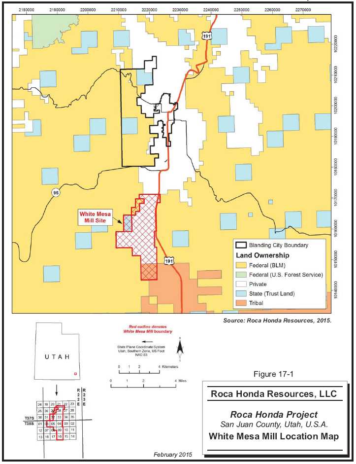
| Roca Honda Resources, LLC– Roca Honda Project, Project #2438 | |
| NI 43-101 Technical Report– February 27, 2015 | Page 17-2 |
| |
www.rpacan.com |

| Roca Honda Resources, LLC– Roca Honda Project, Project #2438 | |
| NI 43-101 Technical Report– February 27, 2015 | Page 17-3 |
| |
www.rpacan.com |

| Roca Honda Resources, LLC– Roca Honda Project, Project #2438 | |
| NI 43-101 Technical Report– February 27, 2015 | Page 17-4 |
| |
www.rpacan.com |
ORE RECEIVING
Ore will be hauled from the Roca Honda Mine to the White Mesa Mill in 24-ton highway haul trucks. When trucks arrive at the White Mesa Mill, they are weighed and probed prior to stockpiling. Samples are collected to measure the dry weight, and to perform amenability testing for process control. Trucks are washed in a contained area, and scanned for gamma radiation prior to leaving the White Mesa Mill site.
GRINDING
A front end loader will transfer the mineralized material from the stockpiles to the White Mesa Mill through the 20 in. stationary grizzly and into the ore receiving hopper. The ore is then transferred to the 6 ft by 18 ft diameter semi-autogenous grinding (SAG) mill via a 54 in. wide conveyor belt. Water is added with the ore into the SAG mill where the grinding is accomplished. The SAG mill is operated in closed circuit with vibrating screens. The coarse material, P80 +28 mesh (28 openings per linear inch) is returned back to the SAG mill for additional grinding and the P80 -28 mesh portion is pumped to the pulp (wet) storage tanks.
The pulp storage tanks are three 35 ft diameter by 35 ft high mechanically agitated tanks. These tanks serve two basic purposes. First, they provide storage capacity for the ore prior to chemical processing; and second, they provide a facility for blending the various types of ore prior to processing.
LEACHING
From the pulp storage tanks, pre-leach and leaching are employed to dissolve the uranium. A hot, strong acid treatment is utilized in the second stage in order to obtain adequate recoveries. This results in high concentrations of free acid in solution. Therefore, a first stage "acid kill" is employed, which is referred to as pre-leach. Ore from the pulp storage tanks is metered into the pre-leach tanks at the desired flow rate. The slurried ore from the pulp storage tanks will usually be about 50% solids mixed with 50% water. This slurry is mixed in the pre-leach tanks with a strong acid solution from the counter current decantation (CCD) circuit resulting in a density of approximately 22% solids. This step is employed to neutralize the excess acid from the second stage leach with raw ore. By doing this, not only is the excess acid partially neutralized, but some leaching occurs in the pre-leach circuit, and less acid is needed in the second stage leach. The pre-leach ore flows by gravity to the pre-leach thickener. Here, flocculent is added and the solids are separated from the liquid. The underflow solids are pumped into the second stage leach circuit where acid, heat, and an oxidant (sodium chlorate) are added. About three hours retention time is expected to be needed in the seven second stage leach tanks. Each tank has an agitator to keep the solids in suspension. The discharge from the leach circuit is a slurry consisting of solids and a sulfuric acid solution with dissolved uranium and vanadium. The leach slurry is then pumped to the CCD circuit for washing and solid liquid separation. The liquid or solution from the pre-leach thickener overflow is pumped first to the clarifier and then the SX feed tank.
| Roca Honda Resources, LLC– Roca Honda Project, Project #2438 | |
| NI 43-101 Technical Report– February 27, 2015 | Page 17-5 |
| |
www.rpacan.com |
COUNTER CURRENT DECANTATION
The CCD circuit consists of a series of thickeners in which the pulp (underflow) goes in one direction, while the uranium/vanadium bearing solution (overflow) goes in a counter current direction. The solids settle to the bottom of the first thickener tank and flocculant is added to each thickener feed to increase the settling rate of the solids. As the pulp is pumped from one thickener to the next, it is gradually depleted of its uranium and vanadium. When the pulp leaves the last thickener, it is essentially barren waste that is disposed of in the tailings cells.
Eight thickeners are utilized in the CCD circuit to wash the acidic uranium bearing liquids from the leached solids. Water or barren solutions are added to the No. 8 thickener and flow counter-current to the solids. As the solution advances toward the No. 1 thickener it carries the dissolved uranium. Conversely the solids become washed of the uranium as they advance toward the last thickener. By the time the solids are washed through the seven stages of thickening they are 99% free of soluble uranium and may be pumped to the tailings pond. The clear overflow solution from No. 1 CCD thickener advances through the pre-leach circuit and pre-leach thickener as previously explained and to the clarifier, which is an additional thickener giving one more step in order to settle any suspended solids prior to advancing the solution to the solvent extraction (SX) circuit.
TAILINGS MANAGEMENT
Tailings solutions (approximately 50% solids) are pumped to the tailings cells for permanent disposal. The sands are allowed to settle and the solutions are transferred to the evaporation cells prior to reuse in the milling process. Additional details on the tailings cells and mill water balance are discussed in the White Mesa Mill portion of Section 19 - Project Infrastructure.
| Roca Honda Resources, LLC– Roca Honda Project, Project #2438 | |
| NI 43-101 Technical Report– February 27, 2015 | Page 17-6 |
| |
www.rpacan.com |
SOLVENT EXTRACTION
The primary purpose of the uranium solvent extraction (SX) circuit is to concentrate the uranium. This circuit has two functions. First, the uranium is transferred from the aqueous acid solution to an immiscible organic liquid by ion exchange. Alamine 336 is a long chain tertiary amine that is used to extract the uranium compound. Then a reverse ion exchange process strips the uranium from the solvent, using aqueous sodium carbonate. As previously noted, the solution extraction (SX) circuit is utilized to selectively remove the dissolved uranium from the clarified leach solution. Dissolved uranium is loaded on kerosene advancing counter currently to the leach solution. The uranium-loaded kerosene and leach solution are allowed to settle where the loaded kerosene floats to the top allowing for separation. The uranium barren leach solution is pumped back to the CCD circuit to be used as wash water. The loaded organic is transferred to the stripping circuit where acidified brine (stripping solution) is added and strips the uranium from the kerosene. Within the SX circuit, the uranium concentrations increase by a factor of four when loading on the kerosene and again by a factor of ten when removed by the stripping solution. The barren kerosene is returned to the start of the SX circuit. The loaded strip solution is transferred to the precipitation circuit.
With respect to impurities removal, the SX circuit of the White Mesa Mill is highly selective to uranium and consistently produces yellowcake in the 98% to 99% purity range. This includes ores that contain vanadium, arsenic, and selenium which have shown to be problematic with other uranium recovery methods. The White Mesa Mill has a vanadium recovery circuit, but it is only operated when the head grades are greater than 2 g/L vanadium. This high of a head grade is only expected when the vanadium to uranium ratio is greater than 3:1. Vanadium recovery is not anticipated from the Roca Honda mineralized material based on the low vanadium content.
PRECIPITATION, DRYING AND PACKAGING
In the precipitation circuit the uranium, which up to this point has been in solution, is caused to precipitate or actually "fall out" of the solution. The addition of ammonia, air, and heat to the precipitation circuit causes the uranium to become insoluble in the acid strip solution. During precipitation, the uranium solution is continuously agitated to keep the solid particles of uranium in suspension. Leaving the precipitation circuit, the uranium, now a solid particle in suspension, rather than in solution, is pumped to a two-stage thickener circuit where the solid uranium particles are allowed to settle to the bottom of the tank. From the bottom of the thickener tank the precipitated uranium in the form of a slurry, about 50% solids, is pumped to an acid re-dissolve tank and then mixed with wash water again. The solution is then precipitated again with ammonia and allowed to settle in the second thickener. The slurry from the second thickener is de-watered in a centrifuge. From this centrifuge, the solid uranium product is pumped to the multiple hearth dryer. In the dryer, the product is dried at approximately 1,200ºF, which dewaters the uranium oxide further and also burns off additional impurities. From the dryer, the uranium oxide (U3O8) concentrated to +95%, is stored in a surge bin and packaged in 55-gallon drums. These drums are then labeled and readied for shipment.
| Roca Honda Resources, LLC– Roca Honda Project, Project #2438 | |
| NI 43-101 Technical Report– February 27, 2015 | Page 17-7 |
| |
www.rpacan.com |
WHITE MESA MILL UPGRADES
ROCA HONDA PROJECT SPECIFIC UPGRADES
The White Mesa Mill was refurbished in 2009, and it does not require any plant related upgrades to process the Roca Honda ore. Additional tailings capacity will be required to facilitate permanent storage of the tailings sands and barren solutions. There are additional, permitted areas available for future tailings storage beyond the current capacity of 3.5 Mt.
The White Mesa Mill is currently licensed to construct Cell 1, Cell 2, Cell 3, Cell 4A, and Cell 4B. Cell 1 is strictly an evaporation pond, and it will continue to be used as one. Cell 1, Cell 2, Cell 3, Cell 4A, and Cell 4B have been built and are currently used for tailings-related process storage. Cell 2 and Cell 3 have been used for tailings disposal over the life of the White Mesa Mill to date. Cell 4A is the current tailings disposal cell, and it has 1.5 million tons (Mt) of capacity remaining. Cell 4B has all of its original two (2) million tons (Mt) of capacity remaining, because it has only been used as a water evaporation pond. Cell 4B was constructed in 2011 at a cost of US$12 million. The estimated cost to reclaim Cell 4B is $2.5 million. The tailing capacity replacement has been estimated at US$5/t of tailings for the Roca Honda ore.
| Roca Honda Resources, LLC– Roca Honda Project, Project #2438 | |
| NI 43-101 Technical Report– February 27, 2015 | Page 17-8 |
| |
www.rpacan.com |
The processing parameters obtained from historical production of the Grants District ores and from the Kerr-McGee metallurgical test work have been shown to be similar to the ores milled in 2009 and 2010 at the White Mesa Mill.
PROCESS DESIGN CRITERIA
The principal design criteria selected are tabulated below in Table 17-1. The process operation parameters will be finalized following testing of site specific metallurgical samples. Required reagents and mill labor is discussed in Section 21 – Capital and Operating Costs of this report.
TABLE 17-1 PRINCIPAL PROCESS OPERATION CRITERIA
Roca Honda Resources LLC – Roca Honda Project
| General | Criteria |
| Processing rate | 547,500 stpa |
| 1,800 stpd | |
| Feed grade | 0.365 % uranium |
| Uranium circuit | |
| Final grind | 80% passing 28 Mesh |
| Typical sulfuric acid consumption | 150 lb/t |
| Final concentrate mass | 122 lb/ft3 |
| Product assay | 97 % U3O8 |
| Recovery to final concentrate | 95% uranium in feed |
| Roca Honda Resources, LLC– Roca Honda Project, Project #2438 | |
| NI 43-101 Technical Report– February 27, 2015 | Page 17-9 |
| |
www.rpacan.com |
18 PROJECT INFRASTRUCTURE
Infrastructure at the Roca Honda mine has been designed to accommodate all mining and transportation requirements. This includes offices, mine dry, warehousing, stockpiles, standby generators, fuelling station, rapid response services, equipment utilities, and workshops.
The Roca Honda Project area is an undeveloped site with gravel road access and no site facilities. The White Mesa Mill is an operating uranium mill six miles from Blanding, Utah with good paved road access on US Highway 191 from the Roca Honda mine site. The proposed Roca Honda Project layout is shown in Figure 16-1. The White Mesa Mill layout is shown in Figure 16-2.
ROCA HONDA ROADS AND ACCESS
Site roads will be required to access the following locations from the mine complex:
| • | Mine shaft | |
| • | Dewatering wells | |
| • | Water treatment plant | |
| • | Mine fresh air raises, two escape way raises, and mine air heater | |
| • | Four secondary mine exhaust raises | |
| • | Water reclaim area |
Site roads will be low-speed, two lane and single lane roads with turnouts to permit vehicles to meet.
A parking area for employee and company vehicles will be provided beside the mine offices.
ACCESS ROAD FROM THE MINE TO THE WHITE MESA MILL
The access road from the site to Highway 605 will be improved during haul road construction. All other roads are paved and in place.
| Roca Honda Resources, LLC– Roca Honda Project, Project #2438 | |
| NI 43-101 Technical Report– February 27, 2015 | Page 18-1 |
| |
www.rpacan.com |
MATERIAL HANDLING AND STORAGE
The storage area at the mine will require space for fuel storage and some bulk materials storage. The yards will be designed to divert surface drainage away from roads and storage yards and appropriate spill response plans will be developed for the various products that are to be handled in the area.
Mine development material will be either be hoisted to the surface and either used for surface construction or stockpiled in storage areas for backfill and reclamation, in temporary locations for run of mine (RoM) mineralized material, or used as backfill in underground excavated areas. The stockpiles of RoM material will subsequently be used as plant feed.
PRODUCT SHIPMENTS
All mill related product storage is in place and shown on Figure 16-2.
Dried yellowcake will be packaged in appropriately labeled, Department of Transportation (DOT)-approved, 55 gal drums, each containing 650 lb to 1,000 lb of dry yellowcake. Yellowcake is classified by the DOT as radioactive material of Low Specific Activity according to 49 Code of Federal Regulations (CFR) 172-178 (CFR, 1976). Each drum will be labeled on two sides with the drum number, net yellowcake weight, and radioactivity stickers labeled “Low Specific Activity” and “Caution - Radioactive Material.”
MINE AND MILL FACILITIES
ROCA HONDA MINE
Offices for site management personnel will be located within the operations complex at the mine. These will include administration, management, mine, process, and maintenance personnel. Mine personnel will have offices in the mine administration building.
WAREHOUSE FACILITIES
A central warehouse located on surface will be established at the mine site. The heated indoor storage will be supplemented with an organized container storage yard and some outdoor lay down area. The warehouse area will be manned by a purchasing agent and an assistant.
| Roca Honda Resources, LLC– Roca Honda Project, Project #2438 | |
| NI 43-101 Technical Report– February 27, 2015 | Page 18-2 |
| |
www.rpacan.com |
MAINTENANCE FACILITIES
The surface maintenance shop will be used for maintenance of all surface and limited, small underground equipment at the mine site. The underground fleet and part of the surface fleet will see service through the year.
The planned underground shop will have service bays for heavy equipment as well as space for light equipment. The shop will be equipped with an overhead crane for servicing equipment.
A machine shop with milling tools, a lathe, saws, and work benches will be installed to provide emergency replacement of parts, if necessary. There will be a welding bay for the repair of boxes and buckets and other welding jobs.
FUEL FACILITIES
Fuel will be loaded at Grants, New Mexico for transport to the mine. A bermed fuel storage area; containing diesel fuel tank(s) will be provided along the main haul access road at the mine and mill areas. This area will include a fuel load out from tankers and dispensing station for vehicles. Fuel dispensing will be monitored to provide documentation of use and environmental compliance. The storage areas will be lined with an impermeable liner and the berm will be large enough to contain the required quantity of fuel based upon storage regulations.
MINE POWER
Electricity is available at the substation with power coming from the New Mexico Energy grid. A new overhead transmission line supplies power to the mine. Back up diesel generation of 5 MW will be required at the mine in case of a power failure. Standby diesel generators for the mine, dewatering wells, water treatment plant will be required, and will be installed in a separate powerhouse so that a major failure or loss of the main power house does not impact the standby units.
MINE WASTE STOCKPILE AREA
The mine waste stockpile has been sized at 11 acres. No special handling is required for the mine waste rock. Mine waste will be placed directly on the ground after the topsoil stripping and grubbing has been completed. The mine waste rock will be hauled from the mine to the stockpile, placed, and spread. This size waste stockpile will accommodate a total of 0.35 million cubicyards of mine waste. Mine development waste will only be stockpiled during initial development and the stockpile is sized assuming that most development waste will be used as backfill during mining operations.
| Roca Honda Resources, LLC– Roca Honda Project, Project #2438 | |
| NI 43-101 Technical Report– February 27, 2015 | Page 18-3 |
| |
www.rpacan.com |
WHITE MESA MILL
There is office space for the administration, technical, mill and maintenance personnel in a central office location at the White Mesa Mill facility.
MILL POWER
Total online power for the White Mesa Mill is presented in Table 18-1. Electrical loads were inventoried from existing equipment. The majority of electrical components installed are low voltage 460 V. Medium voltage, 4,160 V, is used for the SAG mill.
TABLE 18-1 WHITE MESA MILL PLANT ESTIMATED ELECTRICAL LOAD
Roca Honda Resources LLC – Roca Honda Project
| Connected Load Rating | hp | kW | kVA |
| SAG Mill | 700 | 567 | 651 |
| All Pumps | 604 | 489 | 615 |
| Conveyors/Feeders/Screens | 94 | 76 | 95 |
| Agitators/Settlers/Mixers | 550 | 446 | 512 |
| CCD | 200 | 162 | 186 |
| Presses/Flocculant | 22 | 18 | 23 |
| Fans/Scrubbers/Cranes | 45 | 36 | 42 |
| Bag House/Miscellaneous | 91 | 65 | 81 |
| Totals | 2,306 | 1,859 | 2,205 |
| Operating Load Rating | |||
| SAG Mill | 581 | 471 | 540 |
| All Pumps | 451 | 358 | 449 |
| Conveyors/Feeders/Screens | 71 | 55 | 68 |
| Agitators/Settlers/Mixers | 457 | 370 | 425 |
| CCD | 166 | 134 | 154 |
| Presses/Flocculants | 17 | 14 | 18 |
| Fans/Scrubbers/Cranes | 37 | 30 | 35 |
| Bag House/Miscellaneous | 58 | 48 | 60 |
| Totals | 1,838 | 1,480 | 1,749 |
| Roca Honda Resources, LLC– Roca Honda Project, Project #2438 | |
| NI 43-101 Technical Report– February 27, 2015 | Page 18-4 |
| |
www.rpacan.com |
MILL MAKEUP WATER
Fresh water to be used in the uranium leach plant is provided by four existing on site wells.
WHITE MESA TAILINGS MANAGEMENT
GENERAL
The White Mesa Mill is currently licenced to construct Cell 1, Cell 2, Cell 3, Cell 4A, and Cell 4B. Cell 1 is strictly an evaporation pond and will continue to be used as one. Cell 2 and Cell 3 have been used for tailings disposal over the life of the White Mesa Mill. Cell 4A is the current tailings disposal cell and has 1.5 million tons of capacity remaining and Cell 4B has all of its original 2.0 million tons of capacity remaining as it has only been used as a evaporation pond. The next 2 Cells to be installed have already been designed and will be permitted as needed. Tailing cell liner systems are installed to protect groundwater resources.
Cell 4B was constructed in 2011 at a cost of $12 million. The estimated cost to reclaim Cell 4B is $2.5 million. The tailing capacity replacement has been estimated at $5/st of tailings for the Roca Honda ore.
The construction will be scheduled to ensure that there is always sufficient storage capacity available in the facility to avoid overtopping if a major storm event occurs. The embankment provides sufficient freeboard to safely accommodate the supernatant pond and Environmental Design Storm event, combined with wave run-up. A spillway is included to pass the Inflow Design Flood event.
TAILINGS WATER MANAGEMENT
Process solutions are stored in a combination of Cell 1, Cell 4A, or Cell 4B, depending on water storage and evaporation needs.
Water handling records are reported to the State of Utah quarterly to comply with the Groundwater Discharge permit (No. UGW37004).
TAILINGS DEWATERING
During tailings deposition in the tailings cells, solutions are drawn from the cell to maintain capacity for additional tailing solids. When the cells fill to capacity, reclamation is commenced and solutions are continued to be removed from the solids to further protect groundwater resources.
| Roca Honda Resources, LLC– Roca Honda Project, Project #2438 | |
| NI 43-101 Technical Report– February 27, 2015 | Page 18-5 |
| |
www.rpacan.com |
LAYOUT AND DESIGN
The White Mesa Mill site and tailings locations are shown on Figure 16-2. Cell 1, Cell 2, and Cell 3 were installed prior to 40 acre limit being imposed by the US EPA.
TAILINGS PROPERTIES
Mill tailings will be acidic with a pH ranging from one to three. Uranium grade in the tailings should average below 0.02% assuming a 95% recovery of uranium in the mill.
DIVERSION STRUCTURES
Three stormwater diversions currently protect the White Mesa Mill area and tailings cells from large storm events.
SURFACE EQUIPMENT
The surface equipment fleet at the mine will be required for site services on a year round basis plus the seasonal demands of the annual concentrate shipment and resupply. The surface mobile equipment at the mine and mill will be required to support the operation. In light of the potential to hire local equipment from Grants, New Mexico or other local area communities, it will not be necessary to be completely self-sufficient. The White Mesa Mill surface equipment comprises the equipment already on-site.
A list of the surface mobile equipment for the mine is shown in Table 18-2.
| Roca Honda Resources, LLC– Roca Honda Project, Project #2438 | |
| NI 43-101 Technical Report– February 27, 2015 | Page 18-6 |
| |
www.rpacan.com |
TABLE 18-2 SURFACE EQUIPMENT FLEET
Roca Honda
Resources LLC – Roca Honda Project
| Area | Units | Primary Uses |
| Warehouse/Water Treatment Plant/Pipeline Maintenance | ||
| Fork lift | 1 | Freight Handling, Pipelines, General |
| Bobcat | 1 | Mine Clean Up |
| HDPE Pipe Welder | 1 | Water Supply/Dewatering/Tailings Lines |
| Surface | ||
| Fuel Trucks | 1 | Fuel Haul |
| Container Trailers | 1 | Container Moves |
| Pick-up Truck | 2 | Garbage/Maintenance/Inspection |
| Management | ||
| Pick-up Truck | 2 | Management |
| Vans For Crews | 4 | Crew Transportation |
| Ambulance | 1 | Emergency Rescue |
| Fire Truck | 1 | Fire Fighting |
| Spill Response | 1 | |
SECURITY
In view of the remote nature of the mine site, there is little risk to the general public and little risk of public access to the site. There will be occasional visitors in summer, who will come to the site by passenger vehicles. Such visitors will be met with signs and personnel who will explain that this is a private mine and mill site, and visitors are not allowed on site and there are no services available. There will be manned security stations at entrance locations on the mine and mill sites.
Where necessary, fencing will be installed to keep wildlife out of areas such as the reagent storage. The use of containers for storage will minimize the requirement for such fencing.
The White Mesa Mill is fenced. All visitors are required to check in and they are required to have an RHR escort.
MEDICAL FACILITY
The medical facilities at each site (mine or mill) will consist of an appropriately-supplied first aid station, and there will be appropriately qualified first aid personnel on site and on call at all times. First aid rooms will be located in the mine office and mill office complex areas.
| Roca Honda Resources, LLC– Roca Honda Project, Project #2438 | |
| NI 43-101 Technical Report– February 27, 2015 | Page 18-7 |
| |
www.rpacan.com |
An ambulance will be available on site for the transport of injured personnel to the first aid stations and or site helipad. Seriously injured personnel will be evacuated from the mine site by helicopter to Albuquerque, New Mexico or Grand Junction, Colorado in the case of a serious injury at the White Mesa Mill. The ambulance will be certified for operation. A helipad will be constructed at the mine site.
A fire truck will be available on site to respond to surface fire incidents. The surface fire brigade will be a combination of personnel from the site.
Mine rescue gear will be purchased and located within a mine rescue training area in the office complex. Mine rescue personnel will be selected and trained as required under the Mine Safety and Health Administration Rules.
LANDFILL
Garbage will be collected periodically and shipped to the appropriate municipal landfill. Recyclable materials will be collected separately and shipped out annually for processing. A waste management site will be established for the long term storage of waste materials. All waste generated at the White Mesa Mill is disposed of in dedicated areas of the tailing cells.
GREYWATER AND SEWAGE TREATMENT
The greywater and sewage from the mine will be sent to separate sewage treatment facilities (Biodisk or equivalent) after which the water will be discharged. Solids in the sewage treatment units will be removed on an annual basis and disposed at the appropriate municipal treatment facility. The White Mesa Mill utilizes a septic system and leach field to treat sanitary sewage.
| Roca Honda Resources, LLC– Roca Honda Project, Project #2438 | |
| NI 43-101 Technical Report– February 27, 2015 | Page 18-8 |
| |
www.rpacan.com |
19 MARKET STUDIES AND CONTRACTS
MARKETS
The uranium market is controlled by a few traders on both the supply and the demand side. The value of world primary source uranium production is approximately US$5.5 billion per year. That is less than ten percent of the value of newly mined gold production or newly mined copper production.
SUPPLY
According to the International Atomic Energy Agency/OECD Nuclear Energy Agency “Red Book”, world uranium requirements totaled more than 61,600 t U in 2012 and are expected to decrease to 59,370 t U in 2013. In 2011, 2012 and 2013, uranium was produced in 21 different countries, with Germany, Hungary and France producing small amounts of uranium only as the result of mine remediation activities (Bulgaria did not report uranium recovery from mine remediation for the 2014 edition of the Red Book; hence there is one less producing country than in 2010). Kazakhstan’s growth in production continued, albeit at a slower pace, and it remains the world’s largest producer with 21,240 t U produced in 2012 and 22,500 t U expected in 2013. In 2012, production in Kazakhstan amounted to more than the combined 2012 production of Canada and Australia, respectively, the second and third largest producers.
Niger produced 4,822 t U in 2012, which is only slightly more than Namibia which produced 4,653 t U. The top five producing countries (Kazakhstan, Canada, Australia, Niger, and Namibia) retained their dominance accounting for 79% of world production in 2012. Eleven countries, Kazakhstan (36%), Canada (15%), Australia (12%), Namibia (8%), Niger (8%), the Russian Federation (5%), Uzbekistan (4%) and the United States (3%), China (2%), Malawi (2%), and Ukraine (2%) accounted for approximately 97% of world production. In 2013, world uranium production (59,370 t U) provided 100% of world reactor requirements with Kazakhstan, Canada, and Australia accounting for 65% of the production.
In 2013, eight companies marketed 82% of the world's uranium mine production. In 1990, 55% of world production came from underground mines, but since then ISR mining has steadily increased its share of the total. In 2013, underground/open pit mines accounted for 47%, while ISR accounted for 46% with remaining coming from by-product and secondary sources.
| Roca Honda Resources, LLC– Roca Honda Project, Project #2438 | |
| NI 43-101 Technical Report– February 27, 2015 | Page 19-1 |
| |
www.rpacan.com |
DEMAND
Demand is primarily as a source for nuclear power plants. The use of nuclear power generation plants has become increasingly acceptable politically. Both China and India have indicated an intention to increase the percentage of power generated by nuclear plants. The largest increase in demand will come from those two countries.
Because the time required for the permitting, financing, and construction of power plants the increase in demand will be slow. It can be concluded that the demand side of the market is expected to grow, slowly in the near term, but increasingly over the long term. Most, but not all current projections, show that the market will be in a slight oversupply balance in the near term moving into an undersupply balance as early as 2020. Some analysts project a near term undersupply.
PRICE
The key to understanding any mineral market is knowing how the mineral price is determined. There are generally considered to be two prices in the uranium market: 1) long term contract prices, and 2) spot prices. These are published by companies that provide marketing support to the industry with UxC being the most commonly followed price report. Over the long term price follows the classic market force of supply demand balance with a “speculative” investment market that creates price volatility.
There is also a budding futures market for uranium. That, coupled with a “speculative” demand market, may have increased the volatility in the uranium price.
The average annual uranium spot price is shown in Figure 19-1. It may be seen that the price has varied from US$10.00 per pound of U3O8 in 2000 to almost US$100 per pound in 2007. The current uranium spot price is approximately US$39 per pound.
| Roca Honda Resources, LLC– Roca Honda Project, Project #2438 | |
| NI 43-101 Technical Report– February 27, 2015 | Page 19-2 |
| |
www.rpacan.com |
FIGURE 19-1 AVERAGE ANNUAL PRICE – SPOT MARKET 2000-2014
![]()
Source: http://ycharts.com/indicators/uranium_spot_price
Figure 19-2 is an example of forecasts by some of the world’s major banks and uranium traders long-term price. The use of a $65/lb uranium price in this PEA can be considered reasonable if one compares the forecast of uranium price in Figure 19-2.
| Roca Honda Resources, LLC– Roca Honda Project, Project #2438 | |
| NI 43-101 Technical Report– February 27, 2015 | Page 19-3 |
| |
www.rpacan.com |
FIGURE 19-2 MAJOR BANK URANIUM PRICE FORECAST – 2013

Source: http://www.investorsguru.com/ViewNewsletter.html?id=177
CONTRACTS
At this time, RHR has not entered into any long term agreements for the provision of materials, supplies or labor for the Project. The construction and operations will require negotiation and execution of a number of contracts for the supply of materials, services and supplies.
| Roca Honda Resources, LLC– Roca Honda Project, Project #2438 | |
| NI 43-101 Technical Report– February 27, 2015 | Page 19-4 |
| |
www.rpacan.com |
20 ENVIRONMENTAL STUDIES, PERMITTING, AND SOCIAL OR COMMUNITY IMPACT
ROCA HONDA RESOURCES ENVIRONMENTAL POLICY
As a steward of the land and resources in its charge, RHR is committed to working for the wellbeing of its employees and the communities in which it operates. RHR is committed to achieving excellence in all aspects of its operations, in particular health, safety, radiological and environmental protection. It will do so by implementing corporate health, safety and community relations policies and procedures, as well as regulatory requirements and best management practices.
Specifically, RHR will implement the following actions:
| • | Integrate corporate and site-specific environment, health, safety and emergency preparedness policies, management systems, programs and plans with the goal of continuous improvement; | |
| • | Design and operate its facilities to ensure compliance with regulatory and Company requirements and minimize risks to employee and community health and safety and the environment; | |
| • | Meet or exceed all regulatory requirements with respect to protection of environmental resources; | |
| • | Train and equip employees with the understanding, skills and facilities to achieve an injury-free, safe workplace and to fulfill the Company’s environmental obligations; | |
| • | Require on-site contractors to implement practices consistent with Company health, safety, radiological and environmental protection policies, procedures and plans; | |
| • | Train employees and on-site contractors to the site- and job-specific health, safety, radiological and environmental plans; | |
| • | Encourage resource conservation and pollution prevention measures among employees and site contactors; | |
| • | Provide information and training for the safe handling, use, transport, and disposal of radiological and other hazardous materials; | |
| • | Operate radiological areas as low as reasonably achievable; | |
| • | Educate employees on practices to improve on-the-job safety; |
| Roca Honda Resources, LLC– Roca Honda Project, Project #2438 | |
| NI 43-101 Technical Report– February 27, 2015 | Page 20-1 |
| |
www.rpacan.com |
| • | Conduct regular health, safety, radiological, quality assurance and environmental protection audits, identifying and implementing corrective actions as necessary ; and | |
| • | Communicate openly and on a timely basis with employees, the public, government agencies, and other stakeholders on activities involving health, safety, and environmental issues. |
Extensive environmental baseline studies have been completed for the Roca Honda site. A mine permit application was submitted in October 2009, revised in 2011 and deemed administratively complete. The permit application is now undergoing technical review. A Draft EIS was issued by the USFS in February 2013. An ROD and Final EIS is scheduled to be completed by December 2016.
A summary of the major observed baseline conditions, possible risks and mitigation measures are discussed below.
ROCA HONDA
SURFACE FEATURES
Jesus Mesa occupies approximately half of Section 9 and slopes into Section 10. The top and upper portion of the mesa is sparsely vegetated, and the perimeter of the mesa consists of sandstone ledges with areas of exposed shale, particularly to the south of the mesa. The landscape southwest, north, and southeast of the mesa is moderately vegetated, and the slopes are dissected by drainages ranging from a few feet to 40 ft deep.
A local drainage basin, beginning from the base of Jesus Mesa in Section 9, runs south and southwest just east of the center of Section 16. There are also smaller drainages generally running southeast from the highest point in Section 16 on an unnamed mesa at 7,292 ft. Drainages exist on both the west and east sides of this mesa, with steep slopes and cliffs up to 50 ft high. Section 16 is moderately vegetated.
BASELINE STUDIES
RHR prepared an environmental baseline analysis to support a mine permit application. The Baseline Data Report was prepared in 2009 and revised in 2011 to detail baseline environmental conditions at the mine site. Since that time the report has been supplemented as needed to better describe water quality and quantity, wildlife and wildlife habitat, and vegetation resources within the Project area. Details of all baseline activities are documented in the report, and continually updated as needed.
| Roca Honda Resources, LLC– Roca Honda Project, Project #2438 | |
| NI 43-101 Technical Report– February 27, 2015 | Page 20-2 |
| |
www.rpacan.com |
MINE SITE
Environmental Baseline Studies for the mine site were begun in 2006. Methods and results of work to date were documented in the Baseline Data Report and Sampling and Analysis Plan submitted in October 2009 and revised in 2011 to the New Mexico Mining and Minerals Division and the U.S. Forest Service (Cibola National Forest).
The Roca Honda Project area is sparsely populated, rural, and largely undeveloped. The predominant land uses include low density grazing, limited agricultural production, and recreational activities such as hiking, sightseeing, picnicking, firewood gathering, and seasonal hunting.
MILL SITE
Strathmore Resources had previously planned to construct a new mill to process ore from the mine on property owned by Roca Honda Resources about 15 mi north of the mine site. Extensive environmental characterization studies were completed to support permit applications but a source material license application was never submitted to the U.S. Nuclear Regulatory Commission, the federal agency charged with permitting uranium processing facilities. Although Energy Fuels now intends to transport uranium ore to its wholly–owned White Mesa Mill in Blanding, Utah, the baseline studies completed at the proposed mill site would be valuable for future permitting purposes if market conditions eventually justified a “local” mill.
The White Mesa Mill operations and monitoring stations are monitored daily with monthly and quarterly reports to the State of Utah, to demonstrate compliance with State and Federal regulations.
PRIOR MINING ACTIVITIES
No prior mining operations, which may have affected the Project area, exist on the proposed mine area. There were, however, more than 400 historic exploration boreholes drilled from the late 1960s to the early 1980s in various locations throughout the Project area. Additionally, some of the property immediately surrounding the Project area contains drill holes to varying degrees; however, RHR has no knowledge of particular drilling locations in these areas. Field inspections of the these areas conducted in conjunction with other field activities revealed occasional pipe and other markers that may identify possible drill hole locations, but they cannot be confirmed as such. In addition to the drill holes themselves, the USGS mapped a network of drill roads present mainly in Section 9 and 10 that accessed the drill sites. Most of these roads have naturally re-vegetated, but are largely still passable.
| Roca Honda Resources, LLC– Roca Honda Project, Project #2438 | |
| NI 43-101 Technical Report– February 27, 2015 | Page 20-3 |
| |
www.rpacan.com |
HYDROGEOLOGY
The Roca Honda Project area is located in the southeastern part of the San Juan structural basin, within the southeast part of the Ambrosia Lake uranium subdistrict, which was the site of previous uranium mining and associated mine dewatering activities from the 1960s through the 1980s. The Project area lies within the Bluewater Underground Water Basin as extended by the New Mexico Office of the State Engineer on May 14, 1976.
Large amounts of data on groundwater exist for the San Juan Basin because the area contains deposits of recoverable uranium and valuable groundwater resources. The USGS, the New Mexico Bureau of Mines and Mineral Resources, and the New Mexico State Engineer cooperated in several hydrogeological studies of the San Juan Basin, which have described area aquifers and compiled and analyzed groundwater quality data and estimates of hydraulic parameter values (Brod and Stone 1981, Frenzel and Lyford 1982, Stone et al. 1983, Craigg et al. 1989, Dam et al. 1990, Dam 1995, and Craigg 2001). Moreover, as part of the Regional Aquifer System Analysis program, the USGS developed a steady–state multi–aquifer groundwater flow model of the San Juan Basin (Kernodle 1996). Roca Honda Resources developed a comprehensive and accurate model of groundwater occurrences in the southern portion of the San Juan Basin in support of mine permitting efforts. The model was accepted by the New Mexico State Engineer’s Office in 2013 as part of the mine dewatering permit process.
The RocaHonda Project area is approximately three miles northwest of the Mt. Taylor uranium mine formerly operated by Gulf Mineral Resources Company and others, and it is now owned by Rio Grande Resources Corporation (General Atomics). This mine was dewatered during the 1970s and early 1980s. Groundwater quality data and hydraulic parameter estimates were collected both at the Mt. Taylor mine and at various mines west of the Roca Honda Project area in the Ambrosia Lake subdistrict (NMEI 1974, GMRC 1979, and Kelley et al. 1980). The groundwater quality and hydraulic characteristics of the Westwater Canyon Member of the Morrison Formation were re-evaluated more recently during site licensing in the Crownpoint and Church Rock areas (HRI 1988 and 1991 and US NRC 1997).
| Roca Honda Resources, LLC– Roca Honda Project, Project #2438 | |
| NI 43-101 Technical Report– February 27, 2015 | Page 20-4 |
| |
www.rpacan.com |
Historic exploratory drilling conducted by others, and more recent drilling conducted by RHR, determined that the strata beneath the Project area represent the same sequence of rocks found in the San Juan structural Basin.
Potentiometric data collected from wells in and near the Project area indicate that groundwater moves continuously through the Project area in the same aquifers found to the west. The aquifers and aquitards encountered in the Project area likely have hydraulic characteristics similar to those found in the same units elsewhere in the San Juan structural Basin.
In general, the hydraulically significant structural features of the southeastern San Juan Basin have been previously identified, and the groundwater quality and hydraulic characteristics of the aquifers in the Roca Honda Project area are expected to lie within the ranges identified in previous studies. RHR has compiled the relevant published and unpublished groundwater information near the Project area. This effort included an inventory of wells previously identified in published and unpublished reports as being present within a ten mile radius of the Roca Honda Project area. The inventory includes location, completion dates, well depth, producing formation, measured water levels, and availability of chemical data for each well. The wells were field-checked and RHR incorporated some of them, along with three wells drilled by RHR within the Project area, into a quarterly water quality sampling program. The well data inventory, earlier studies, recent drilling by RHR, and the water quality sampling program provide a great deal of baseline information for the groundwater in and adjacent to the Project area. To date, RHR has collected four years of water quality data, contracted Intera Geosciences and Engineering (Intera) to complete a groundwater model and conducted an onsite pump test in May 2010.
SURFACE HYDROLOGY
Watercourses in the vicinity of the RHR Project area are identified as ephemeral, intermittent, or perennial. San Mateo Creek is part of the Rio Grande drainage basin as a tributary of the Rio San Jose. The Rio San Jose joins the Rio Puerco west of the city of Las Lunas and the Rio Puerco confluences with the Rio Grande near the community of Bernardo, south of the town of Belen, New Mexico.
| Roca Honda Resources, LLC– Roca Honda Project, Project #2438 | |
| NI 43-101 Technical Report– February 27, 2015 | Page 20-5 |
| |
www.rpacan.com |
The headwaters of San Mateo Creek are on the north flank of Mt. Taylor. One branch heads in San Mateo Canyon above the community of San Mateo and drains down San Mateo Canyon, while the other drains the San Mateo arch/Jesus Mesa area via Marquez and Maruca canyons. Within the San Mateo Canyon branch, springs maintain a small perennial flow that is captured in San Mateo Reservoir, located above the community of San Mateo. Field investigations conducted by RHR during 2009 and 2010 have determined that from San Mateo downstream to a pond on the Lee Ranch, San Mateo Creek is an intermittent stream that has flow when water is being diverted from the reservoir for irrigation purposes and during high rainfall events. The creek is ephemeral downstream of the pond.
POLITICAL DISCUSSION
The development of clean, sustainable energy is a goal supported by the Government of New Mexico. The state appears to be moving in a pro-development, pro-energy direction, and recent discussions between RHR representatives and the State of New Mexico government indicate support within the administration for developing nuclear energy-related projects, including uranium mining.
Sensitivity related to development of the Roca Honda Project exists relative to the historic use and cultural significance of the area to the native peoples, whose use of the area dates to prehistoric times. Archaeological evidence indicates that the Anasazi, Basketmaker, and Pueblo cultures have all used the Project area and, more recently, the Navajo and Anglo cultures as well.
In April 2008, the USFS determined that certain areas of Mt. Taylor and certain surrounding forest property, known commonly as the Mt. Taylor Traditional Cultural Property (TCP), were eligible for listing on the National Register of Historic Places (NRHP). Sections 9 and 10 of the Project area are within the boundary of the proposed USFS Mount Taylor TCP. Additionally, Section 11, through which access will be gained to Section 10, is also in the TCP. Figure 20-1 indicates the boundary of the TCP.
Although the State designation was contested in court, the New Mexico Supreme Court ultimately upheld the TCP designation. Designation of a TCP does not preclude mineral development or prohibit mining operations within the TCP; it just adds another layer of regulatory review and opportunity for stakeholders in the Section 106 Consultation process to seek more mitigation than might otherwise be required.
| Roca Honda Resources, LLC– Roca Honda Project, Project #2438 | |
| NI 43-101 Technical Report– February 27, 2015 | Page 20-6 |
| |
www.rpacan.com |
POTENTIAL IMPACTS OF THE PROPOSED MINE
Impacts to water resources at and around the Roca Honda Project area were evaluated as part of a groundwater model report produced for RHR by Intera (Nov. 4, 2011). The Roca Honda Project could impact area water resources in three ways:
| 1. |
Depressurizing of the mine may cause local water level declines within the confined aquifer system present in the Westwater Canyon Member of the Morrison Formation. Water levels in the Dakota Sandstone, and possibly sandstone units in the lower part of the Mancos Shale may be locally affected. It is unlikely that depressurizing will impact water levels in the aquifers relied on by water users in the San Mateo area, who use wells that produce from the shallow aquifers in the alluvium, i.e., the Menefee Formation, and the Point Lookout Sandstone. These geologic units are from 2,000 ft to 2,300 ft above the units to be dewatered. Groundwater in aquifers below the Westwater Canyon Member will not be impacted by mine dewatering because an aquitard, the Recapture Shale Member of the Morrison Formation, underlies the Westwater Canyon Member and separates the aquifers. | |
| 2. |
Shallow aquifers, which may be vulnerable to potential impacts from facility activity or from discharged water include the alluvium, the Point Lookout Sandstone, and the Dalton Sandstone Member of the Crevasse Canyon Formation. Although the Menefee Formation is used as an aquifer in the San Mateo Creek watershed, it is not present down gradient of the proposed surface facility area. It is present, however, beneath colluvium in the SE¼ Section 10. | |
| 3. |
The treated mine water will be piped to the community of Milan to assist in recharging the Rio San Jose. An influx of this quantity of water into the overlying soil/alluvium found in the irrigated area will likely raise the water table. The water produced from depressurizing activities will be treated to state and federal water discharge standards. Therefore, there will be no adverse impact on water quality within the alluvial aquifer or other formations recharged by the discharge where they outcrop in the arroyo. |
| Roca Honda Resources, LLC– Roca Honda Project, Project #2438 | |
| NI 43-101 Technical Report– February 27, 2015 | Page 20-7 |
| |
www.rpacan.com |

| Roca Honda Resources, LLC– Roca Honda Project, Project #2438 | |
| NI 43-101 Technical Report– February 27, 2015 | Page 20-8 |
| |
www.rpacan.com |
Groundwater in aquifers below the Westwater Canyon Member will not be impacted by mine depressurizing because geologic units of low vertical permeability underlie the Westwater Canyon Member and separate the Westwater Canyon Member from underlying aquifers. Specifically, the mine workings will be in the Westwater Canyon Member, and the shaft will extend through the Westwater Canyon Member a few tens of feet into the underlying aquitard, the Recapture Member of the Morrison Formation.
Groundwater flow modeling was performed to estimate the impacts of mine depressurizing on ground and surface water systems in and near the Project area. The model predicted that the maximum drawdown in the Gallup Sandstone causes a 10 ft drawdown contour to extend no further than the Project area; the maximum drawdown in the Dakota Sandstone causes a 10 ft drawdown contour to extend approximately to a 2,000 ft radius around the shaft; and the maximum drawdown in the Westwater Canyon Member causes a 10 ft drawdown contour to extend eight to ten miles out from the mine areas. These drawdowns would be expected to cause temporary water level declines in wells in each of these three formations within these radii. Since the Gallup and Dakota Sandstones are only depressurized during shaft sinking, recovery of these aquifers begins shortly after shaft sinking is complete. Recovery in the Westwater Canyon Member does not begin until mining operations and depressurizing has ceased. The New Mexico Office of the State Engineer (NMOSE) determined that three domestic wells would be impacted by dewatering of the Westwater Canyon Member. Those wells are subject to Plans of Replacement approved by the NMOSE. RHR will be responsible for supplying water to or drilling new wells for those three well owners.
The potential impact of mine depressurizing on perennial stream systems was analyzed using the RIVER package of MODFLOW-2000. The groundwater flow model simulated that the impact of depressurizing on area streams would be negligible. As part of the mine dewatering permit process, RHR demonstrated that potential impacts to seeps and springs, including those of primary concern to downstream pueblos, would be undetectable to insignificant.
All stormwater runoff within the mine site or from disturbed areas will either be diverted around the disturbed areas or captured and conveyed to stormwater retention ponds so there will be no surface discharge of water from the site. All chemical, fuel, and explosives storage areas will be bermed to contain potential spills or leaks. All mine water and water pumped from dewatering wells will be conveyed to a lined surge pond and passed through the water treatment plant to meet discharge standards prior to release via the reuse pipeline. Consequently no detrimental impacts to surface water resources are expected to occur.
| Roca Honda Resources, LLC– Roca Honda Project, Project #2438 | |
| NI 43-101 Technical Report– February 27, 2015 | Page 20-9 |
| |
www.rpacan.com |
PROJECT PERMITTING
ROCA HONDA PERMITTING
PERMITTING REQUIREMENTS - STATE
Mine permitting authority in New Mexico resides primarily with the Mining and Minerals Division (MMD) of the New Mexico Energy, Minerals, and Natural Resources Department. The permitting process entails preparation of three major documents: a Sampling and Analysis Plan, a Baseline Data Report, and a Mining, Operations and Reclamation Plan. In October 2009, RHR submitted a five volume Mine Permit application to the MMD that included a detailed Sampling and Analysis Plan, a Baseline Data Report, Mining Operations Plan, and a Reclamation Plan. MMD determined that the application was administratively complete in November 2009 and commenced a technical review of the application documents.
The New Mexico Environment Department (NMED) regulates mining operations through the issuance of a Discharge Permit and establishment of standards for discharges or potential releases from mining operations. The Discharge Permit requires characterization of all materials or structures (e.g., waste rock piles) that could be exposed to environmental dispersal agents, and designs for all systems that will be used to prevent or control potential releases to the environment (e.g., liner systems for ponds). RHR submitted a Discharge Permit application to the NMED in January 2009.
Mine dewatering is regulated by the New Mexico Office of the State Engineer (NMOSE) through approval of a Mine Dewatering Permit. Under the Mine Dewatering Act, the applicant is required to provide a Plan of Replacement for wells or other water sources that could be impaired by the proposed dewatering activities over the Projected life of the mine. Water pumped from the mine is considered “produced” water and conveys no water right but can used for beneficial purposes. RHR submitted a mine dewatering permit application in August 2011.
These three permit applications constitute the major State approvals needed for new mining projects in New Mexico. Most of the planned mine facilities would be located in Section 16 on State lands. Therefore a Mining Lease is also required from the New Mexico State Land Office (NMSLO) to authorize mine development and operation. RHR obtained a State Mining Lease for Section 16 in November 2004.
| Roca Honda Resources, LLC– Roca Honda Project, Project #2438 | |
| NI 43-101 Technical Report– February 27, 2015 | Page 20-10 |
| |
www.rpacan.com |
PERMITTING REQUIREMENTS- FEDERAL
Sections 9, 10, and 11 are Federally-owned lands managed by the USFS. Prior to any development or mining activities on those lands, the Cibola National Forest (CNF) must prepare an EIS for the Project. RHR submitted a Plan of Operations to the CNF in October 2009 and the CNF issued a Notice of Intent to prepare an EIS in November 2010.
Following the publication of the Notice of Intent, the MMD, NMED, the State Historic Preservation Office (SHPO) and the New Mexico Division of Game and Fish (NMDG&F) signed a Memorandum of Understanding (MOU) with RHR and the USFS, agreeing to participate in a “mutually beneficial, cooperative relationship” in preparing the EIS. MMD is a cooperating agency (with the USFS), but it must also prepare a separate Environmental Evaluation (EE) of the Project. As part of the MOU, MMD agreed to use the EIS prepared by the USFS as the basis for the EE. The SHPO is involved in the Section 106 consultation process and must review and approve the reports prepared by the USFS, and sign off on the Memorandum of Agreement when it is complete.
Other Federal approvals needed are a discharge permit (NPDES) for the dewatering pipeline and approval of radon releases from the mine under the National Emission Standards for Hazardous Air Pollutants (NESHAPS), both issued by the U.S. Environmental Protection Agency (EPA). RHR applied for an NPDES permit in April 2012. A NESHAPS notification will be submitted to EPA at least 18 months before shaft construction is anticipated to begin.
Table 20-1 lists the major permits needed to construct a new underground uranium mine on federal land in the State of New Mexico. Because there would be no processing or concentrating of natural ore at the mine site, no U.S. Nuclear Regulatory Commission (NRC) approvals are needed.
| Roca Honda Resources, LLC– Roca Honda Project, Project #2438 | |
| NI 43-101 Technical Report– February 27, 2015 | Page 20-11 |
| |
www.rpacan.com |
TABLE 20-1 MAJOR AND MINOR ROCA HONDA PERMITS
Roca
Honda Resources LLC – Roca Honda Project
| Agency | Permit or Approval |
| Federal | |
| U.S. Forest Service | Plan of Operations (plan) |
| Special use permits (right-of ways, etc.) | |
| U.S. Army Corps of Engineers | Nationwide 44 Permit (Section 404 compliance) |
| U.S. Environmental Protection Agency | Spill Prevention Control and Countermeasures Plan (SPCC) |
| Notification of Hazardous Waste Activity | |
| Storm Water Pollution Prevention Plan (SWPPP) | |
| Subpart A of the Radionuclide National Emission Standards for | |
| Hazardous Air Pollutants (NESHAPs) | |
| National Pollutant Discharge Elimination System (NPDES) permit | |
| U.S. Fish and Wildlife Service | Threatened and Endangered Species (Section 7 Consultation) |
| Federal Communications Commission | Radio authorizations |
| U.S. Department of Transportation | Requirements for transport and handling of radioactive material |
| including ore | |
| Treasury Department (Bureau of Alcohol, | Explosives use permits |
| Tobacco, Firearms and Explosives) | |
| Mine Safety and Health Administration | Mine Identification Number |
| Legal Identity Report | |
| Ground Control Plan | |
| Miner Training Plan | |
| Worker exposure standards | |
| State | |
| New Mexico Energy, Minerals and | New Mine Permit |
| Natural Resources, Department, Mining | |
| and Minerals Division | |
| New Mexico Environment Department | Discharge Permit |
| Groundwater Bureau | |
| New Mexico Environment Department | Public water supply system |
| Drinking Water Bureau | |
| New Mexico Environment Department | Solid Waste System Permit |
| Waste Management Bureau | |
| New Mexico Environment Department | Registration of diesel and petroleum tanks |
| Petroleum Storage Tank Bureau | |
| New Mexico Environment Department | Radiation Control License for Nuclear Dentistry Gauge |
| Radiation Control Bureau | |
| New Mexico Office of the State Engineer | Permit to Appropriate Waters |
| Mine Dewatering Permit | |
| Dam Safety | |
| Drilling Permit | |
| New Mexico State Land Office | Mining Lease (Sec. 16) |
| Commercial Lease | |
| New Mexico Game & Fish Department | Wildlife consultation |
| State Historic Preservation Office | Section 106 (NHPA) consultation |
| New Mexico Department of | Road Access |
| Transportation | ROW and Pipeline Construction |
| McKinley County | |
| Building Department | Building Permits |
| Septic System Approval |
| Roca Honda Resources, LLC– Roca Honda Project, Project #2438 | |
| NI 43-101 Technical Report– February 27, 2015 | Page 20-12 |
| |
www.rpacan.com |
CURRENT PERMIT STATUS
The status of major, long-lead time permits as of February 1, 2015 follows.
USFS EIS
The CNF issued a Draft EIS for the Roca Honda mine to the public in March 2013. Since then, the CNF and its third party contractor have been preparing responses to comments on the DEIS and working through the Section 106 Consultation process as required by the National Historic Preservation Act. RHR recently requested that the final EIS include evaluation of an alternate mine dewatering pipeline plan that would deliver water to a different drainage than was evaluated in the Draft EIS. In response to this request, the CNF has indicated that preparation of a Supplemental EIS will be necessary. Current expectations are that preparation of a supplemental EIS document will take most of 2015. The USFS projects that issuance of a final EIS and completion of the Memorandum of Agreement required under the Section 106 consultation process will occur in the fourth quarter 2016.
Permit to Mine
The MMD has issued several rounds of comments based on their technical review of the Mine Permit application documents, all of which have been addressed. Recent discussions confirm that MMD will evaluate the southern reuse pipeline option as part of the existing permit application. MMD has also prepared a Scope of Work for the Environmental Evaluation and confirmed that it can be derived from the EIS and modified as needed to meet specific state regulatory requirements.
Discharge Permit
The NMED has completed its administrative and technical review of the Discharge Permit application. In order to evaluate the southern pipeline discharge alternative, NMED requested a Work Plan describing how possible impacts from the discharge will be characterized and monitored. RHR is presently conducting geophysical surveys and other characterization work of the proposed discharge area in the Rio San Jose. RHR expects that a draft discharge permit can be prepared within six months of submittal of the results of the work plan.
Mine Dewatering Permit
On-going discussions with Acoma Pueblo intended to resolve their concerns have been fruitful and withdrawal of the dewatering permit appeal is anticipated in early 2015. Acoma Pueblo has stated that it will withdraw the appeal, subject to two conditions that RHR has recently satisfied. The first is a formal commitment to pursue the southern dewatering pipeline alternative that would convey treated water to the Rio San Jose, a normally dry drainage some 20 mi south of the mine that runs through Acoma Pueblo lands. The second condition is that the water treatment plant will produce clean water that meets applicable water quality standards. Bench test work completed under the direction of Pennoni Associates demonstrates that the treated water will meet all applicable criteria.
| Roca Honda Resources, LLC– Roca Honda Project, Project #2438 | |
| NI 43-101 Technical Report– February 27, 2015 | Page 20-13 |
| |
www.rpacan.com |
State Mining Lease
The New Mexico State Land Office has agreed to rely on the results of the EIS and State mine permitting processes to address environmental considerations pertinent to development of a mine on the lease land. The lease is currently in effect but will need to be amended or extended if production from Section 16 does not commence by November 2019. A Commercial Lease may also be needed to allow stockpiling of materials from off-lease (i.e. Sections 9 and10) although that requirement is unclear.
Other Permits Status
The U.S. Army Corps of Engineers has been involved in the EIS process since inception and has indicated that it will issue a “Nationwide” 44 permit for the Project, which involves a less onerous approval process than that required for an individual permit. The NPDES application was submitted to EPA in April 2012 and is currently being amended to incorporate the southern reuse pipeline alternative. As noted earlier, RHR will prepare a NESHAPS notice to the EPA at least 18 months prior to commencing shaft construction work.
At the State level, the NMED must determine that the Project as designed will achieve compliance with all applicable air and water quality standards. NMED has determined an air quality permit to construct and operate is not needed for the Project. Certification of compliance with State water quality standards will be provided as part of the MMD permitting process. A Stormwater Pollution Prevention Plan will need to be filed the State and EPA prior to construction activities.
Resource studies and engineering work to support the new discharge pipeline plan are currently underway, using qualified third party consulting firms. In parallel, RHR staff are revising relevant sections of the NMED Discharge Permit and the MMD Permit to Mine applications to incorporate the new mine discharge alternative. Other permits or notifications shown in Table 20-1 are of secondary importance and can be obtained within the time frame projected for the EIS and Permit to Mine. Those permits include solid waste disposal permits, construction permits for the dewatering pipeline, and highway access permits from the New Mexico Department of Transportation.
| Roca Honda Resources, LLC– Roca Honda Project, Project #2438 | |
| NI 43-101 Technical Report– February 27, 2015 | Page 20-14 |
| |
www.rpacan.com |
The overall permitting process has been delayed by RHR’s proposal for a new mine dewatering option that was not previously considered. Regulatory agencies, elected officials, and the Acoma Pueblo are very supportive of the new alternative that would discharge treated water into the Rio San Jose where it could be used by a variety of parties including the Acoma and Laguna Pueblos. Although there will be permitting delays while the USFS prepares a Supplemental EIS to address this alternative, and other permit applications are revised, RHR expects that the new alternative will reduce opposition to the Project. Additionally, the likelihood of successful appeals or challenges to approvals once issued will be diminished.
SOCIAL OR COMMUNITY REQUIREMENTS
The public participation process was initiated in late 2010, with scoping meetings held in Grants and Gallup to fully inform the local citizens of RHR’s mining plans and to allow for their input. This was part of the EIS process. RHR will continue to provide Local, State and Federal agencies with additional detailed design information regarding the Project as it is developed and respond to agency comments. RHR staff maintain frequent communication with representatives of local governmental entities and organizations, and uses local contractors whenever possible for Project development work. In addition, RHR has also been involved in on-going discussions with interested stakeholders, most notably the Acoma and Laguna Pueblos.
ARCHAEOLOGICAL AND TRADITIONAL CULTURAL PROPERTY
Consideration of archaeological and cultural resources is an important part of the USFS and State of New Mexico permitting processes. Initial cultural resource surveys of the Roca Honda Project area were conducted by Lone Mountain Archaeological Services, Inc. (LMASI) in 2006. Prior to the field survey, a literature search was conducted of the National Register of Historic Places (NRHP), the State Register of Cultural Properties, the Archaeological Records Management Section of the State Historic Preservation Division (HPD), and the Cibola National Forest Office in Albuquerque, New Mexico. Following the literature search, detailed field surveys were completed to identify cultural resources within the Project area boundary and proposed accesscorridors, so that appropriate mitigation measures could be implemented in advance of any construction and operations. Archaeological sites were inventoried and mapped and as required by the State of New Mexico SHPO and USFS regulations. Detailed inventory reports prepared by LMASI and submitted to the USFS and SHPO for review.
| Roca Honda Resources, LLC– Roca Honda Project, Project #2438 | |
| NI 43-101 Technical Report– February 27, 2015 | Page 20-15 |
| |
www.rpacan.com |
RHR has designed all anticipated surface disturbances to avoid the archeological sites identified during the initial and follow-up surveys, wherever possible. The footprint of proposed surface disturbances, including all mine site construction and access routes, was located on a map provided to LMASI for their review and field checked to determine potential impacts to archaeology sites. Although facility layouts were adjusted to avoid eligible archaeological sites wherever feasible to do so, LMASI identified several sites that could be affected by construction or operations. Mitigation of possible impacts to such sites will be required, likely in the form of data recovery prior to disturbance.
In conjunction with the EIS, Section 106 of the National Historic Preservation Act requires the USFS to consult with potentially affected parties including Native American communities. A significant consultation process is underway to ensure that Native communities and other stakeholders have the opportunity to express concerns and provide comments. RHR will continue to work with the State and federal agencies, and respective Native communities to addressall issues and develop appropriate mitigation measures, particularly for archaeological sites that may be disturbed by Project development.
MINE CLOSURE REQUIREMENTS
ROCA HONDA RECLAMATION
Reclamation and closure of the entire mine and mill plant facilities will be conducted in accordance with the methods and commitments made in the Mining, Operations and Reclamation Plan (MORP), as amended.
Reclamation and closure will be based on the following general objectives:
| • | Reclamation goals and objectives will be considered during design and planning of construction and operations; | |
| • | Concurrent (progressive) reclamation will be implemented where possible; |
| Roca Honda Resources, LLC– Roca Honda Project, Project #2438 | |
| NI 43-101 Technical Report– February 27, 2015 | Page 20-16 |
| |
www.rpacan.com |
| • | Upon cessation of operations, the areas will be decommissioned and rehabilitated to allow for future land use as guided by the federal, state and local agencies; and | |
| • | Reclamation and closure will ensure that long-term physical and chemical stability is provided. |
The initial reclamation and closure plan prepared for the mine and mill plant facilities will be living documents that will be updated throughout the Project’s life to reflect changing conditions and the input of the applicable federal and state regulatory agencies.
The primary reclamation activities will involve backfilling mine workings, removal of surface facilities and infrastructure, re-contouring and scarifying disturbed areas, applying stockpiled organics, and re-vegetation in accordance with seed mixtures and methods specified in the MORP.
RECLAMATION AND CLOSURE
A detailed closure plan will be developed for the Project. The closure plan will be developed using the guidelines noted above. The total calculated closure and reclamation costs for the Roca Honda Project are currently estimated to be $11.9 million as used in the economic cash flows. The reclamation estimate for the Roca Honda Mine is estimated to be US$3.4 million.
RHR will be required to post a reclamation performance bond with the State of New Mexico prior to approval of the Permit to Mine. The New Mexico Mining and Minerals Division (MMD) regulations allow for phased bonding so RHR intends to bond initially for approximately $1,000,000 to cover the cost of plugging the Phase 1 dewatering wells, removing the associated piping, and reclaiming the access roads, water treatment plant, and storm water retention pond. The USFS has agreed to accept the bond required by MMD so dual bonding will not be necessary.
| Roca Honda Resources, LLC– Roca Honda Project, Project #2438 | |
| NI 43-101 Technical Report– February 27, 2015 | Page 20-17 |
| |
www.rpacan.com |
21 CAPITAL AND OPERATING COSTS
CAPITAL COST ESTIMATE
The capital cost estimate summarized in Table 21-1 covers the life of the Project and includes initial capital costs, expansion capital costs, and end-of-mine-life recovery of working capital. All capital costs are in first quarter 2015 United States dollars.
TABLE 21-1 CAPITAL COST ESTIMATE
Roca Honda
Resources LLC – Roca Honda Project
| Capital Cost Area | Units | Project | Pre-production | Production |
| Capital Totals | (Years -4 to 0) | (1 to 11) | ||
| Underground Mine | US$ (000) | 127,229 | 127,229 | - |
| Mill | US$ (000) | - | - | - |
| Surface Infrastructure | US$ (000) | 46,893 | 46,893 | - |
| Surface Infrastructure Indirects | US$ (000) | 29,148 | 27,146 | 2,001 |
| Working Capital | US$ (000) | - | 5,075 | (5,075) |
| Exploration | US$ (000) | 2,517 | 2,517 | - |
| Sustaining Capital | US$ (000) | 71,972 | - | 71,972 |
| Closure & Reclamation | US$ (000) | 3,400 | - | 3,400 |
| Total Capital Before Contingency | US$ (000) | 281,159 | 208,861 | 72,298 |
| Contingency | US$ (000) | 45,354 | 44,978 | 375 |
| Total Capital Cost With Contingency | US$ (000) | 326,512 | 253,839 | 72,673 |
Working capital costs, related to the time between the shipment from the site and the receipt of payment for the products, are not included in the capital cost estimate in Table 21-1, but are included in the Project cash flow.
CAPITAL COST EXCLUSIONS
The capital costs do not include:
| • | Costs to obtain permits | |
| • | Costs for feasibility study | |
| • | Project financing and interest charges | |
| • | Escalation during construction | |
| • | Sales and use taxes |
| Roca Honda Resources, LLC– Roca Honda Project, Project #2438 | |
| NI 43-101 Technical Report– February 27, 2015 | Page 21-1 |
| |
www.rpacan.com |
| • | Any additional civil, concrete work due to the adverse soil condition and location | |
| • | Import duties and custom fees | |
| • | Costs of fluctuations in currency exchanges | |
| • | Sunk costs | |
| • | Pilot Plant and other test work | |
| • | Corporate administration costs in Santa Fe, New Mexico and Lakewood, Colorado | |
| • | Exploration activities | |
| • | Salvage value of assets |
CAPITAL COST ESTIMATE DETAILS
MINE AND SURFACE CAPITAL COST ESTIMATE
Mine equipment will be purchased through the pre-production period. Mine development includes activities prior to mine stope development. Ventilation and escapeway raise development costs include conventional raise boring and contractor costs.
SURFACE INFRASTRUCTURE AND EQUIPMENT
Surface equipment is estimated using new equipment. Used equipment is estimated for low use equipment such as the grader and cranes.
Infrastructure includes roads, yards, power and supplies storage needs for Roca Honda Project including the materials handling requirements at White Mesa Mill.
WHITE MESA MILL
The White Mesa Mill is fully permitted, has all necessary Federal, State, and NRC licenses, and is currently operating as a viable uranium mill. It also has all of the necessary impoundment structures.
SURFACE INDIRECT COSTS AND TOTAL INDIRECT COSTS
The surface infrastructure indirect costs are estimated to be $29.1 million as summarized in Table 21-2. The surface indirect costs exclude embedded indirect costs allocated to the underground mine constructioncontractsand surfaceinstallation construction contracts. Total Project indirect costs are approximately $43.0 million as shown in Table 21-2. Engineering for the facilities and operations will be carried out through the permitting and the construction phases. Engineering costs for the completion of the feasibility engineering are included in this estimate.
| Roca Honda Resources, LLC– Roca Honda Project, Project #2438 | |
| NI 43-101 Technical Report– February 27, 2015 | Page 21-2 |
| |
www.rpacan.com |
TABLE 21-2 SURFACE INFRASTRUCTURE INDIRECT COST ESTIMATE AND
TOTAL INDIRECT COST ESTIMATE
Roca Honda Resources LLC – Roca Honda
Project
| Capital Cost Estimate Surface Indirects | Units | Total ($'000) |
| Engineering; Feasibility (Mine only) | $'000 | 250 |
| Engineering; Basic (Mine only) | $'000 | 500 |
| Engineering; Detailed (Mine only) | $'000 | 700 |
| Transportation (8% of equip costs) (Mine only) | $'000 | 1,493 |
| 1st year spares (4% of equip costs) (Mine only) | $'000 | 548 |
| Capital Spares (Mill - 6% of equip costs) | $'000 | 1,645 |
| Capital Spares & Warehouse Inventory (Mine) | $'000 | 800 |
| Water Treatment Plant | $'000 | 1,317 |
| Construction Management (Mine only) | $'000 | 650 |
| Working Capital (Separate in Cash Flow) | $'000 | - |
| First Fills (Mine only) | $'000 | 150 |
| Owner's Cost | $'000 | 21,093 |
| TOTAL SURFACE INDIRECTS | $'000 | 29,148 |
| F-K Indirect Costs (Included in F-K Estimate) | $'000 | 7,951 |
| Contractor Indirect Costs (Included in Contractor Costs) | $'000 | 3,249 |
| Surface Mine, Water Treatment Plant, Powerline Indirects | $'000 | 29,148 |
| Surface Infrastructure Engineering | $'000 | 2,645 |
| Total Indirects | $'000 | 42,993 |
Procurement for the Project is forecast to extend over a three-year period with a crew of three working on purchasing, expediting, payables and some level of freight handling. The construction management at Roca Honda is forecast to include a staff of four to five management personnel for a two-year period. After construction, most of the personnel will continue on with operations. Supervisor salary rates for this period reflect the overtime in a remote construction effort.
The construction support crew includes operators for cranes, forklifts and trucks, as well as laborers to support the construction efforts. The cost estimate includes construction support items that would be rented or provided by subcontractors in a less remote location.
The Owners costs include an Owner’s team of eight staff for two years prior to the commencement of development and operations. In addition, a labor cost for operating personnel brought to site in advance of the “startup” is included. The estimate is based upon a staff and crew of 160 in 2017. Costs for the recruitment of the operating team are included. Freight costs for the White Mesa Mill plant are carried in those individual capital estimates.
| Roca Honda Resources, LLC– Roca Honda Project, Project #2438 | |
| NI 43-101 Technical Report– February 27, 2015 | Page 21-3 |
| |
www.rpacan.com |
The environmental bond is estimated to be $11.9 million for the combined Roca Honda Mine and White Mesa Mill sites (for the Roca Honda mineralized material only).
The cost estimate includes a contingency allowance of 16%. RPA considers this to be a minimum level of contingency for the Project at the current state of planning and development.
OPERATING COST ESTIMATE
The average LoM operating costs and the annual estimated operating costs are shown in Table 21-3. The LoM average operating cost includes mining, processing the White Mesa Mill located near Blanding, Utah, general and administration, and freight of the product to a point of sale (White Mesa Mill). Operating costs are in February 2015 United States dollars.
TABLE 21-3 OPERATING COST ESTIMATE
Roca Honda
Resources LLC – Roca Honda Project
| Operating Cost Summary | Units | Cost |
| Mining & Development (includes mine maintenance) | US$ (000) | 368,136 |
| Transportation Cost | US$ (000) | 149,314 |
| Processing (Includes Tailings Reclamation/Replacement Cost) | US$ (000) | 167,022 |
| Toll Milling Process Cost Average | US$ (000) | 123,227 |
| Maintenance (labor) | US$ (000) | 2,647 |
| G&A | US$ (000) | 18,418 |
| Total Operating | US$ (000) | 828,763 |
| Mining & Development | US$/t mined | 86.55 |
| Mining & Development | US$/t milled | 107.25 |
| Transportation Cost | US$/t milled | 43.50 |
| Processing (includes Tailings Reclamation/Replacement Cost) | US$/t milled | 48.66 |
| Toll Milling Process Cost Average | US$/t milled | 35.90 |
| Maintenance | US$/t milled | 0.77 |
| G&A | US$/t milled | 5.37 |
| Total Operating Cost per Ton | US$/t milled | 241.45 |
| Mining & Development | US$/lb | 15.65 |
| Transportation Cost | US$/lb | 6.35 |
| Processing (includes Tailings Reclamation/Replacement Cost) | US$/lb | 7.10 |
| Toll Milling Process Cost Average | US$/lb | 5.24 |
| Maintenance | US$/lb | 0.11 |
| G&A | US$/lb | 0.78 |
| Total Operating Cost per lb | US$/lb | 35.23 |
| Roca Honda Resources, LLC– Roca Honda Project, Project #2438 | |
| NI 43-101 Technical Report– February 27, 2015 | Page 21-4 |
| |
www.rpacan.com |
OPERATING COST EXCLUSIONS
The operating costs do not include:
| • | Any provision for inflation; | |
| • | Any provision for changes in exchange rates; | |
| • | Sales and use taxes; | |
| • | Preproduction period expenditures; | |
| • | Corporate administration and head office costs in Santa Fe, New Mexico and Lakewood, Colorado; | |
| • | Site exploration costs or surface infill drilling or development for conversion of additional resources to Mineral Resources; and | |
| • | Severance cost for employees at the cessation of operations. |
SALARY AND LABOR RATES
Salary and wage rates are based on prevailing regional wage and salary surveys in the Project area. Federal Insurance Contributions Act (FICA) tax is estimated at 7.65% tax on the wage and salary costs.
Wages have been not been adjusted either downward or upward given the nature of the work and the location. RPA does consider this element to be a cost risk. Skilled operators, maintenance and technical personnel live in the surrounding area of Grants, New Mexico.
An allowance for workman’s compensation, health insurance, bonuses, FICA, and other benefits are included in the labor rates.
FUEL PRICE AND FUELTAXES
Operating costs are based upon a diesel fuel price of $3.20/gal FOB mine site. The freight costs are from Grants, New Mexico to the Roca Honda site.
Propane has been included at a cost of $0.51/therm. Natural gas is an option, but requires pipeline construction to the proposed mine site. RPA considers this to be a cost risk as natural gas or propane prices vary over a wide range. RHR may benefit from purchasing an annual supply in the summer months.
| Roca Honda Resources, LLC– Roca Honda Project, Project #2438 | |
| NI 43-101 Technical Report– February 27, 2015 | Page 21-5 |
| |
www.rpacan.com |
MINE
Mine costs include all of the underground mining costs except for haulage of material from the mine to the crusher operation, which is included in the White Mesa Mill operating costs estimate. The costs are summarized in Table 21-4.
TABLE 21-4 UNDERGROUND MINE COST SUMMARY
Roca
Honda Resources LLC – Roca Honda Project
| Area | Cost | LoM | % of LoM |
| US$ Per RoM ton | US$ millions | Budget | |
| Labor | 48.72 | 167.23 | 45% |
| Ground Support | 16.63 | 57.07 | 16% |
| Electrical | 5.51 | 18.90 | 5% |
| Drilling | 1.73 | 5.93 | 2% |
| Blasting | 4.37 | 14.99 | 4% |
| Ventilation | 3.28 | 11.26 | 3% |
| Services, Roads, and Propane | 5.53 | 18.97 | 5% |
| Water Treatment (W/O Electricity) | 2.55 | 8.75 | 2% |
| Definition Drilling | 1.31 | 4.50 | 1% |
| Maintenance | 17.63 | 60.53 | 16% |
| Mine Operating Totals | 107.25 | 368.14 | 100% |
The major mine supplies are electricity, explosives, ground support, fuel and propane for mine air heat. Mine power costs are included in the overall power cost estimate for the site.
An average powder factor of 1.34 lb/ton was used for costing purposes. Given the uncertain level of groundwater drainage in the development headings, explosives costs have been based on the use of hand loaded emulsion cartridges (Orica Senatel Magnafrac small diameter detonator sensitive emulsion). Explosives costs could be reduced (from $1.82/lb to $0.60/lb) by replacing the cartridges with a bulk loading system and ANFO.
Mobile equipment costs are estimated on annual operating hours and equipment utilization.
Salary and wages are included as single line items and are not allocated to the various activities in the mine.
Backfill placement is included in the mine costs at a cement addition rate of 4.5% for low strength backfill and 8% for high strength backfill. The cost of obtaining the quarried and screened rock component of the high strength backfill is estimated at $9.00/st FOB site. Annual cement requirement is estimated at 17,600 tons.
| Roca Honda Resources, LLC– Roca Honda Project, Project #2438 | |
| NI 43-101 Technical Report– February 27, 2015 | Page 21-6 |
| |
www.rpacan.com |
MILL
Mill operating costs are summarized in Tables 21-5 and 21-6. An allowance for workman’s compensation, health insurance, bonuses, FICA, and other benefits were also added into the labor costs.
TABLE 21-5 MILL OPERATING COST DETAILS BY AREA
Roca Honda Resources LLC – Roca Honda Project
| Typical Mill | Typical Mill Unit | ||
| Unit Operating Cost, | Operating Cost, | ||
| Mill Operating Cost by Area | US$/t ore | % of Total | US$/lb recovered |
| Mill Administration | 1.92 | 4.6% | 0.28 |
| Legal | 0.76 | 1.8% | 0.11 |
| Taxes, Bonding, & Insurance | 2.73 | 6.5% | 0.39 |
| Lab/Mill Technical | 1.28 | 3.1% | 0.19 |
| Safety/Environmental/Rad. | 1.88 | 4.5% | 0.27 |
| Compliance | 0.99 | 2.4% | 0.14 |
| Ore Receiving | 0.73 | 1.8% | 0.11 |
| Warehouse | 0.69 | 1.7% | 0.10 |
| Grinding | 2.36 | 5.7% | 0.34 |
| Leach | 15.82 | 38.0% | 2.29 |
| CCD | 1.70 | 70.0% | 0.25 |
| Uranium SX | 6.54 | 15.7% | 0.95 |
| Uranium Precipitation | 0.79 | 1.9% | 0.11 |
| Uranium Drying and Packaging | 1.55 | 3.7% | 0.22 |
| Tailings | 1.91 | 4.6% | 0.28 |
| Mill Operating Cost by Area | 41.66 | 100.0% | 6.03 |
Reagent costs shown in Table 21-6 are considered as element costs. The mill area costs as shown in Table 21-5 contain summaries of element costs, e.g., reagents, electricity, labor, wear parts, supplies, etc.
| Roca Honda Resources, LLC– Roca Honda Project, Project #2438 | |
| NI 43-101 Technical Report– February 27, 2015 | Page 21-7 |
| |
www.rpacan.com |
TABLE 21-6 MILL OPERATING REAGENT USAGE DETAILS
Roca Honda Resources Inc. – Roca Honda Project
| Reagents Description | Typical Usage Unit |
US$/Usage Unit |
Typical Usage Unit/ton of ore |
Cost, US$/ton |
| Kerosene | gal | 6.03 | 0.50 | 3.02 |
| Soda Ash | lb | 0.12 | 4.50 | 0.54 |
| International Barrels | bbl | 66.00 | 0.01 | 0.49 |
| Grinding Media/Liners | lb | 0.59 | 0.80 | 0.47 |
| Chlorate | lb | 0.61 | 3.50 | 2.14 |
| Flocculent | lb | 2.36 | 0.32 | 0.76 |
| Salt | lb | 0.08 | 0.90 | 0.07 |
| Amines | lb | 4.83 | 0.20 | 0.97 |
| Caustic Soda | lb | 0.38 | 1.50 | 0.57 |
| Iso-decanol | lb | 1.60 | 0.15 | 0.24 |
| Ammonium Sulfate | lb | 0.29 | 0.20 | 0.06 |
| Sulfuric Acid | lb | 0.08 | 137.00 | 10.28 |
| Anhydrous Ammonia | lb | 0.49 | 0.05 | 0.02 |
| Propane | gal | 1.69 | 0.00 | 0.00 |
| LNG | gal | 0.28 | 9.00 | 2.52 |
| Reagents Costs (Typical, will vary by ore type) | 22.14 | |||
The White Mesa Mill operating costs are based on the listed line items identified to the level of detail available for the PEA study. The accuracy of the operating cost estimate is +/- 25% level of accuracy. The operating personnel costs are based on the actual number of operating, maintenance, overhead personnel required to operate the facility using experienced workers, and on salaries provided by Energy Fuels. The reagent and comminution media costs, based on fourth quarter 2015 budget pricing obtained from suppliers, include an operating period freight cost. The reagent costs are based on average mid-range consumptions provided by Energy Fuels for the White Mesa Mill. The minimum and maximum ranges provided in the PEA imply that the reagent cost is appropriately noted. The major reagent cost is the cost of sulfuric acid at $240/ton. Power is based on electrical power cost of $0.06/kWh for the White Mesa Mill and Roca Honda sites. These power costs are based on actual power rates for the White Mesa Mill and published power rates for the Roca Honda Mine.
| Roca Honda Resources, LLC– Roca Honda Project, Project #2438 | |
| NI 43-101 Technical Report– February 27, 2015 | Page 21-8 |
| |
www.rpacan.com |
ROCA HONDA SURFACE
The Roca Honda surface costs include the operation and maintenance of the surface facilities and the operation of the surface equipment for the maintenance of roads and movement of materials and supplies. The costs are shown in Table 21-7.
TABLE 21-7 SURFACE MAINTENANCE COSTS
Roca Honda
Resources LLC – Roca Honda Project
| Typical Cost per Ton | |
| Description | US$/t milled |
| Maintenance Labor | 0.77 |
ROCA HONDA ADMINISTRATION
The administrative costs for the Roca Honda site cover the mine site administration on the basis that the operation is a stand-alone site with site management, purchasing, payroll and accounts payable handled by site personnel. Health and safety and environment are also included in the mine administration. The administrative costs are summarized in Table 21-8.
TABLE 21-8 ADMINISTRATION
COSTS
Roca Honda Resources LLC – Roca Honda Project
| Administration Cost Summary | Typical Cost per Ton |
| US$/t milled | |
| Direct Labor | 1.45 |
| General and Administration Operating | 3.09 |
| Site Services | 0.82 |
| Total | 5.37 |
Crew transportation costs are included for the transportation of employees to the mine and the White Mesa Mill from Grants, New Mexico.
SALES AND MARKETING
Sales and marketing costs are included for the sales manager and personnel to manage the loading and handling of product at the White Mesa Mill. There are no allowances for sales related travel and activities. The shipping cost from the White Mesa Mill to the buyer is included.
| Roca Honda Resources, LLC– Roca Honda Project, Project #2438 | |
| NI 43-101 Technical Report– February 27, 2015 | Page 21-9 |
| |
www.rpacan.com |
POWER – ROCA HONDA
Power for the Roca Honda site will be generated from commercially supplied line power with diesel units as emergency backup for shaft hoist, dewatering pumps, water treatment, and mill critical pumps and essential equipment. The operating costs are based on the price of $0.06/kWh of electrical power, and the installation of power factor management facilities to run a power factor near unity. The estimated annual power generation operating costs are shown in Table 21-9.
TABLE 21-9 POWER GENERATION
COSTS
Roca Honda Resources LLC – Roca Honda Project
| Description | Annual Budget |
| US$ (000) | |
| Mine Power | |
| Electricity - pumping (surface and underground) | 1,615 |
| Electricity - ventilation (surface and underground) | 156 |
| Electricity - drilling and other | 141 |
| Electricity - hoist | 314 |
| Water Treatment | 188 |
| Mill Power Costs | 634 |
| Total Operating Power Costs | 3,048 |
The annual fuel requirement for electrical power generation at Roca Honda is considered to be inconsequential.
LABOR AND WORK SCHEDULES
Table 21-10 summarizes the staffing requirements for the RHR Project and White Mesa Mill operations during the peak production period.
| Roca Honda Resources, LLC– Roca Honda Project, Project #2438 | |
| NI 43-101 Technical Report– February 27, 2015 | Page 21-10 |
| |
www.rpacan.com |
TABLE 21-10 MINE AND MILL STAFF REQUIREMENTS
Roca
Honda Resources LLC – Roca Honda Project
| Type | Department | Number of Employees |
| Total | Admin | 7 |
| Total | Maintenance | 3 |
| Total | Mine | 247 |
| Total | Processing | 80 |
| Total | 337 | |
| Hourly | Admin | 1 |
| Hourly | Maintenance | 0 |
| Hourly | Mine | 219 |
| Hourly | Processing | 74 |
| Hourly Total | 294 | |
| Staff | Admin | 6 |
| Staff | Maintenance | 3 |
| Staff | Mine | 28 |
| Staff | Processing | 6 |
| Staff Total | 43 |
The following is a typical list of schedules for different working areas for the mine and mill, which were used in this study:
| • | Most Administration: | Monday through Friday, 8 am to 5 pm; | |
| • | Mill: | 4 crews working 2 shifts per day, 7 day/week 12 hour/shift | |
| • | Mine: | 4 Crews, 7 day/week, 3 shift/day, 8 hour/shift |
| Roca Honda Resources, LLC– Roca Honda Project, Project #2438 | |
| NI 43-101 Technical Report– February 27, 2015 | Page 21-11 |
| |
www.rpacan.com |
22 ECONOMIC ANALYSIS
RPA conducted an economic analysis of the Roca Honda Project based on underground mining at an average rate of 1,085 stpd. The Project base case uses a market price of US$65 per pound U3O8 for all years. The cash flow results are presented as pre-tax, and as an estimate of after tax.
The base case for the Roca Honda Project has a production life of approximately nine years and an undiscounted pre-tax LoM cash flow totals $317 million including contingency. Payback occurs early in the fifth year of production. Average annual uranium oxide production during operation is 2.7 million pounds per year. The Project returns a positive pre-tax cash flow without considering the addition of revenue from toll milling of ores from mines independent of Energy Fuels.
Table 22-1 summarizes the economics for the Project for the base case.
RPA notes that the purpose of contingency costs is to account for the unknowns in estimating the cost of a project and to provide an estimated allowance for those uncertainties.
| Roca Honda Resources, LLC– Roca Honda Project, Project #2438 | |
| NI 43-101 Technical Report– February 27, 2015 | Page 22-1 |
| |
www.rpacan.com |
TABLE 22-1 PROJECT ECONOMICS SUMMARY BASE CASE (NO TOLL MILLING)
Roca Honda Resources LLC – Roca Honda Property
| Description | Input | Units | Total | ||||||
| Production | |||||||||
| Roca Honda Production | Tons (000) | 3,432 | |||||||
| Payable Roca Honda Resource Uranium | lb (000) U3O8 | 23,526 | |||||||
| Revenue | |||||||||
| Roca Honda Revenue | US$ (000) | 1,529,213 | |||||||
| Royalty, Product Transport, and Severance Tax Charges | US$ (000) | 56,534 | |||||||
| Net Revenue | US$ (000) | 1,472,679 | |||||||
| Operating Cost | US$ (000) | 828,763 | |||||||
| Operating Cost | US$/lb U3O8 | 35.23 | |||||||
| Capital Cost With Contingency: | US$ (000) | 326,512 | |||||||
| Capital Cost (with contingency) | US$/lb U3O8 | 13.88 | |||||||
| Economics | |||||||||
| Pre-tax CF (with contingency) | US$ (000) | 317,403 | |||||||
| After-tax CF (with contingency) | US$ (000) | 233,967 | |||||||
| Pre-tax NPV (with contingency) | 5% | US$ (000) | 125,199 | ||||||
| Pre-tax NPV (with contingency) | 8% | US$ (000) | 57,996 | ||||||
| Pre-tax NPV (with contingency) | 12% | US$ (000) | 1,341 | ||||||
| IRR (with contingency) | % | 12% | |||||||
| After-tax NPV (with contingency) | 5% | US$ (000) | 74,314 | ||||||
| After-tax NPV (with contingency) | 8% | US$ (000) | 19,632 | ||||||
| After-tax NPV (with contingency) | 12% | US$ (000) | (25,391 | ) | |||||
| IRR (with contingency) | % | 9% | |||||||
| Mining & Development | US$/lb U3O8 | 15.65 | |||||||
| Transportation Cost | US$/lb U3O8 | 6.35 | |||||||
| Processing (includes Tailings Reclamation/Replacement Cost) | US$/lb U3O8 | 7.10 | |||||||
| Toll Milling Process Cost Average | US$/lb U3O8 | 5.24 | |||||||
| Maintenance | US$/lb U3O8 | 0.11 | |||||||
| G&A | US$/lb U3O8 | 0.78 | |||||||
| Total Operating Cost per lb | US$/lb U3O8 | 35.23 |
| Roca Honda Resources, LLC– Roca Honda Project, Project #2438 | |
| NI 43-101 Technical Report– February 27, 2015 | Page 22-2 |
| |
www.rpacan.com |
CONTINGENCY FACTORS
The following contingency percentages were applied to the capital costs based on the capital expenditure timing, level of detail with regards to the estimation, and risk involved with regards to the expenditure.
| • |
Mill Contingency – Not Estimated – White Mesa Mill to be used, which is permitted and operating | |
|
| ||
| • |
Mine Contingency (Average of 16%) |
| • |
Estimation Accuracy Contingency 7% | |
| • |
Mine Omissions Contingency 13% |
| • |
Surface Infrastructure Contingency 25% | |
|
| ||
| • |
Indirects Contingency 15% |
TAXES
United States payroll (or employment) taxes are applied to the Project’s labor costs asa benefit cost. This cost was estimated at 7.65% of the gross salary up to a maximum of $106,800.
The Project economics are on a pre-tax basis. No Federal, State, or local income taxes are included. No capital depreciation schedules are included.
ECONOMIC CRITERIA
The economic analysis contained in this report is based, in part, on Inferred Resources, and is preliminary in nature. Inferred Resources are considered too geologically speculative to have mining and economic considerations applied to them and to be categorized as Mineral Reserves. There is no certainty that economic forecasts on which this PEA is based will be realized.
A pre-tax cash flow projection has been generated from the LoM schedule and capital and operating cost estimates, and is summarized in Table 22-2. A summary of the key criteria is provided below.
REVENUE
| • |
Processing of up to an average of 1,085 stpd of Roca Honda material (base case). | |
| • |
Waste mining of 0.82 Mt. | |
| • |
Mill recovery averaging 95%Metal price: US$65.00 per pound U3O8. | |
| • |
Revenue is recognized at the time of production. |
| Roca Honda Resources, LLC– Roca Honda Project, Project #2438 | |
| NI 43-101 Technical Report– February 27, 2015 | Page 22-3 |
| |
www.rpacan.com |
CAPITAL AND OPERATING COSTS
| • |
Pre-production period of 54 months . | |
| • |
Mine life of nine years. | |
| • |
Toll milling charge of $35.90 per ton. | |
| • |
Pre-production capital cost of $254 million including contingency of $45 million. | |
| • |
Sustaining capital costs of $72 million. | |
| • |
Closure capital cost of approximately $3.4 million. | |
| • |
Total mine life capital cost of $326 million including contingency. | |
| • |
Total LoM operating cost of $829 million. |
ROYALTIES
| • |
There is a New Mexico mining royalty payable on the “value” of mineral production for New Mexico state leases. The royalty is based upon the operating cash flow less a development allowance, depreciation and a processing allowance. | |
| • |
New Mexico mining and private royalties on value of minerals extracted as shown below: |
| • |
Notional Gross Royalty (1%); | |
| • |
Section 9 Gross Royalty (1%); and | |
| • |
Section 16 New Mexico State Lease Royalty (5%). |
| Roca Honda Resources, LLC– Roca Honda Project, Project #2438 | |
| NI 43-101 Technical Report– February 27, 2015 | Page 22-4 |
| |
www.rpacan.com |
TABLE 22-2 PRE-TAX CASH FLOW SUMMARY
Roca Honda Resources, LLC - Roca Honda
Project

| Roca Honda Resources, LLC– Roca Honda Project, Project #2438 | |
| NI 43-101 Technical Report– February 27, 2015 | Page 22-5 |
| |
www.rpacan.com |

| Roca Honda Resources, LLC– Roca Honda Project, Project #2438 | |
| NI 43-101 Technical Report– February 27, 2015 | Page 22-6 |
| |
www.rpacan.com |
Considering the Project on a stand-alone basis, the base case undiscounted pre-tax cash flow and including contingency totals $317 million over the mine life, and payback occurs early in the fifth year of production. The annual uranium production during operation is 2.7 million pounds per year (1,450 tons of uranium oxides) and a maximum annual production of 3.9 million pounds.
The pre-tax internal rate of return (IRR) is 12% and the pre-tax net present value (NPV) is as follows:
| • | $317 million at a 0% discount rate; | |
| • | $125 million at a 5% discount rate; | |
| • | $58 million at an 8% discount rate; and | |
| • | $1 million at a 12% discount rate. |
The net revenue per pound of product is $62.60, and the operating cost per pound of product is $35.23/lb.
SENSITIVITY ANALYSIS
Project risks can be identified in both economic and non-economic terms. Key economic risks were examined by running cash flow sensitivities:
| • | Uranium Oxide price | |
| • | Head Grade | |
| • | Recovery | |
| • | Operating Cost per ton milled | |
| • | Capital Cost |
Sensitivity has been calculated over a range of variations based on realistic fluctuations within above listed factors.
The sensitivities are shown in Figure 22-1 and Table 22-3. The Project is most sensitive and equally sensitive to head grade, uranium price, and recovery, and least sensitive and equally sensitive to operating cost, and capital cost. The sensitivities to metallurgical recovery and head grade are identical to that of price (for all constituents combined) and are therefore plotted on the same line.
| Roca Honda Resources, LLC– Roca Honda Project, Project #2438 | |
| NI 43-101 Technical Report– February 27, 2015 | Page 22-7 |
| |
www.rpacan.com |
FIGURE 22-1 SUMMARY OF ROCA HONDA SENSITIVITY ANALYSIS (PRE-TAX)

| Roca Honda Resources, LLC– Roca Honda Project, Project #2438 | |
| NI 43-101 Technical Report– February 27, 2015 | Page 22-8 |
| |
www.rpacan.com |
TABLE 22-3 SENSITIVITY ANALYSIS
Roca Honda
Resources LLC – Roca Honda Project
| Parameter Variables | Units | -33% | -13% | Base | 20% | 30% |
| U3O8 Price | $/lb | 43 | 56 | 65 | 78 | 87 |
| Pre-tax NPV @ 8% | ($ millions) | -171 | -34 | 58 | 196 | 287 |
| IRR | % | -11% | 5% | 12% | 20% | 24% |
| Parameter Variables | -25% | -10% | Base | 10% | 25% | |
| Grade | % | 0.27 | 0.32 | 0.36 | 0.40 | 0.45 |
| Pre-tax NPV @ 8% | ($ millions) | -113 | -10 | 58 | 126 | 229 |
| IRR | % | -3% | 7% | 12% | 16% | 22% |
| Parameter Variables | -20% | -10% | Base | 2% | 3% | |
| Recovery | % | 76 | 86 | 95 | 97 | 98 |
| Pre-tax NPV @ 8% | ($ millions) | -80 | -11 | 58 | 72 | 79 |
| IRR | % | 1% | 7% | 12% | 13% | 13% |
| Parameter Variables | -20% | -10% | Base | 10% | 20% | |
| Operating Cost | $ millions | 542 | 678 | 829 | 995 | 1,176 |
| Pre-tax NPV @ 8% | ($ millions) | 192 | 129 | 58 | -20 | -104 |
| IRR | % | 20% | 16% | 12% | 6% | -2% |
| Parameter Variables | -30% | -15% | Base | 15% | 30% | |
| Capital Cost | $ millions | 242 | 284 | 327 | 369 | 411 |
| Pre-tax NPV @ 8% | ($ millions) | 120 | 89 | 58 | 27 | -5 |
| IRR | % | 18% | 15% | 12% | 10% | 8% |
COMPARISON WITH THE 2012 PEA
The significant changes between the 2012 PEA and the 2015 PEA are listed in Table 22-4, and the sensitivity financial impacts of these changes are listed in Table 22-5 and Figure 22-2.
RPA notes that the uranium price used for the 2015 PEA is $65/lb and the uranium price used for the 2012 PEA was $75/lb. Table 22-5 shows that if a $75/lb price is used for the 2015 Roca Honda PEA, the pre-tax IRR is only one percent less than the 2012 Roca Honda PEA.
| Roca Honda Resources, LLC– Roca Honda Project, Project #2438 | |
| NI 43-101 Technical Report– February 27, 2015 | Page 22-9 |
| |
www.rpacan.com |
TABLE 22-4 MAJOR DIFFERENCES BETWEEN THE 2012 ROCA HONDA PEA AND THE 2015 ROCA HONDA PEA
Roca Honda Resources LLC – Roca
Honda Project
| Item Changed in PEA | 2012 PEA Assumption | 2015 Assumption | Comment |
| Uranium Price | US$75/lb | US$65/lb | |
| Process Plant Location | Peña Ranch, NM | Blanding, UT | |
| Mill Capital Cost (Directs, Indirects, & Contingency) | US$120 million | US$0 | |
| Ventilation Shaft(s) Method | Blind Bore | Raise Boring | |
| Transportation Distance | 25 to 29 road miles | 275 road miles | |
| Transportation Cost (mine to mill) | US$4.05/t ore | US$43.50/t ore | |
| Toll Milling Charge of Roca Honda Material | US$0.00/t ore | US$35.90/t ore | |
| Water Pipeline | 10 mile Northern Route | 26 mile Southern Route | |
| Capital Cost Estimate (Life of Mine) | US$445 million | US$327 million | |
| Process Plant | New Construction | Existing – White Mesa Mill (WMM) | |
| Process Plant Permitting | Unknown – High Risk – Very Long Lead Time to Obtain NRC | In place – Low Risk | No NRC license required with the WMM |
| Process Recovery Used | 94% | 95% | EFR has processed many different types of uranium ores at their existing White Mesa Mill. |
TABLE 22-5 FINANCIAL COMPARISON BETWEEN THE 2012 ROCA
HONDA PEA AND THE 2015 ROCA HONDA PEA
Roca Honda Resources LLC – Roca
Honda Project
| Description | Units | Price Sensitivities and Recovery | |||||||||||||||||||
| Date of PEA | Feb-15 | Feb-15 | Feb-15 | Feb-15 | Feb-15 | Aug-12 | |||||||||||||||
| Uranium Price | US$/lb | 45.00 | 55.00 | 65.00 | 75.00 | 90.00 | 75.00 | ||||||||||||||
| Processing Recovery | % | 95 | 95 | 95 | 95 | 95 | 94 | ||||||||||||||
| Pre-tax Cash Flow | $ | US 000s | (137,472 | ) | 89,965 | 317,403 | 544,840 | 885,997 | 713,087 | ||||||||||||
| Pre-tax NPV @ 8% Discount Rate | $ | US 000s | (153,637 | ) | (47,821 | ) | 57,996 | 163,812 | 322,536 | 220,075 | |||||||||||
| Pre-tax IRR | % | -8 | 4 | 12 | 18 | 26 | 19 | ||||||||||||||
| Roca Honda Resources, LLC– Roca Honda Project, Project #2438 | |
| NI 43-101 Technical Report– February 27, 2015 | Page 22-10 |
| |
www.rpacan.com |
FIGURE 22-2 COMPARISON OF 2015 ROCA HONDA PEA AT DIFFERENT
URANIUM PRICES TO 2012 ROCA HONDA PEA AT US$75/LB
![]()
Energy Fuels believes that the financial risk of permitting a mill in New Mexico is greater than the risk of using the existing White Mesa Mill in Blanding, Utah. In addition, Energy Fuels believes that the capital cost risk is lower using the White Mesa Mill than building a mill near the Roca Honda Mine. Operating costs for the processing of Roca Honda material at the White Mesa Mill are higher because of the transportation cost from the Roca Honda Mine to the White Mesa Mill.
| Roca Honda Resources, LLC– Roca Honda Project, Project #2438 | |
| NI 43-101 Technical Report– February 27, 2015 | Page 22-11 |
| |
www.rpacan.com |
23 ADJACENT PROPERTIES
CURRENT LAND HOLDINGS
Uranium Resources, Inc. (URI) controls, through mining claims and leases, approximately 3,688 acres of public and private land holdings surrounding and adjacent to the RHR property. URI’s holdings consist of one section of private mineral lease (Section 17, Township 13 North, Range 8 West) and 187 federal unpatented lode mining claims (all or portions of Sections 2, 3, 4, 5, 6, 8, 11, and 12, all in T13N, R8W). Rio Grande Resources (RGR) controls private mineral leases on Sections 13 and 15, T13N, R8W, and additional property associated with the Mount Taylor Mine. RHR disputes the current claims held by URI on Sections 5 and 6. Both companies’ filings with the BLM for those two sections are current. Section 14, T13N, R8W is held by three separate families through private mining leases. From the 1970s through the 1980s, exploration holes were drilled on the properties by various operators. Table 23-1 summarizes the “Non-Reserve” Mineralized Material estimates published in 2007 when all three properties were controlled by URI (Behre Dolbear, 2007).
TABLE 23-1 “NON-RESERVE” MINERALIZED MATERIAL– URI’S SECTIONS 13, 15, AND 17
| Section | Tons | Grade | Pounds U3O8 | Current | Source |
| (000) | (%U3O8) | (000) | Owner | ||
| 13 | 2,400 | 0.16 | 7,600 | RGR | URI, 2007 |
| 15 | 560 | 0.24 | 2,700 | RGR | URI, 2007 |
| 17 | 718 | 0.337 | 4,833 | URI | October 29, 2014 Technical Report |
Note: CIM definitions were not followed.
PAST MINING
In the late 1980s, Kerr-McGee sank a shaft to a depth of approximately 1,469 ft on Section 17, referred to as the Lee mine (also known as the Roca Honda mine). Excavation of the shaft stopped before reaching the mineralized horizons of the Westwater Formation, and the mine closed down in the mid-1980s. No ore was ever mined from the Lee Mine.
By the end of 1982, Kerr-McGee reported total production from seven of their nearby mines in the Ambrosia Lake district of 17.9 million tons grading 0.217% U3O8 containing 77.3 million pounds U3O8 (Malone, 1980 and 1982).
| Roca Honda Resources, LLC– Roca Honda Project, Project #2438 | |
| NI 43-101 Technical Report– February 27, 2015 | Page 23-1 |
| |
www.rpacan.com |
Rio Grande Resources Corporation owns the Mount Taylor underground uranium mine located approximately 3.5 miles southeast of the Roca Honda Project area. More than eight million pounds U3O8 were produced from the Mount Taylor mine before it was placed on standby in 1989. Presently, the Mount Taylor mine is on standby, but is currently working with the State of New Mexico to go back to active status.
The Johnny M mine is located one mile west of the Project area, on Section 7 and the east half of Section 18. Approximately five million pounds U3O8 were mined from the Westwater Canyon Member sandstone units from 1976 to 1982 (Fitch 2010).
Approximately four miles southwestof the Project area is the San Mateo underground uranium mine. This mine has not been in operation for many years; however, approximately 2.8 million pounds U3O8 were mined from 1959 to 1970 (McLemore et. al. 2002).
RPA has not verified the information on the adjacent properties. This information is not necessarily indicative of the mineralization at the Roca Honda property.
Figure 23-1 illustrates the locations of the adjacent properties.
| Roca Honda Resources, LLC– Roca Honda Project, Project #2438 | |
| NI 43-101 Technical Report– February 27, 2015 | Page 23-2 |
| |
www.rpacan.com |
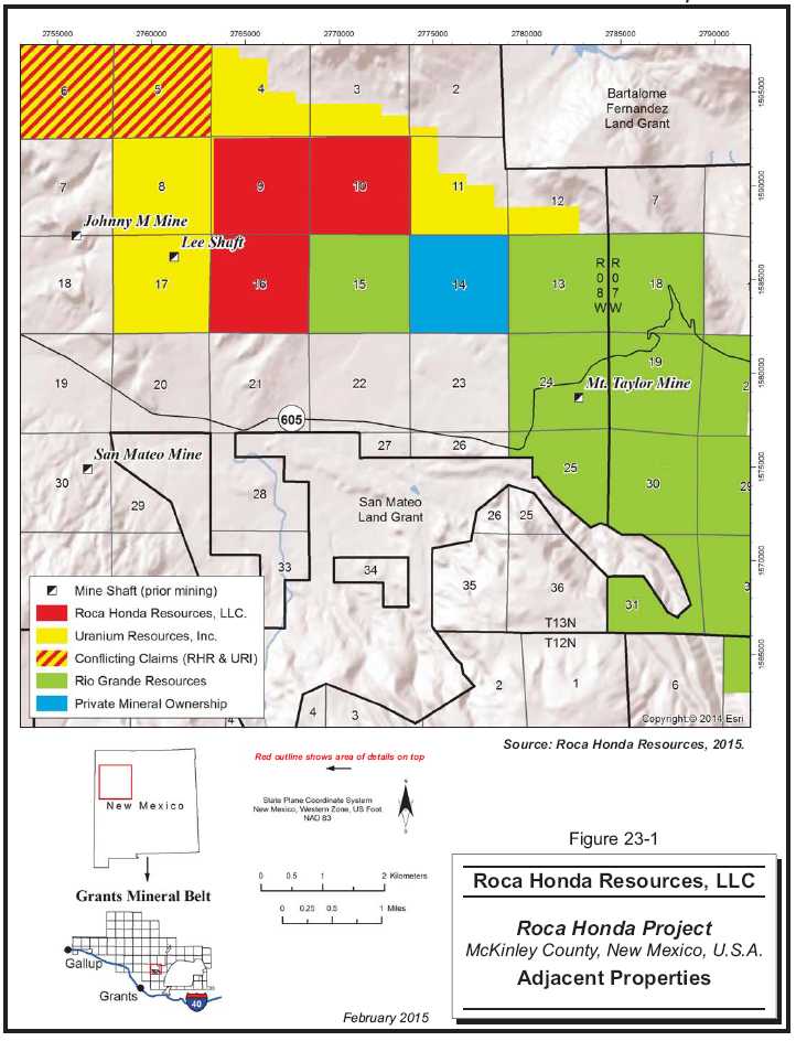
23-3
| Roca Honda Resources, LLC– Roca Honda Project, Project #2438 | |
| NI 43-101 Technical Report– February 27, 2015 | Page 23-3 |
| |
www.rpacan.com |
24 OTHER RELEVANT DATA AND INFORMATION
No additional information or explanation is necessary to make this Technical Report understandable and not misleading.
| Roca Honda Resources, LLC– Roca Honda Project, Project #2438 | |
| NI 43-101 Technical Report– February 27, 2015 | Page 24-1 |
| |
www.rpacan.com |
25 INTERPRETATION AND CONCLUSIONS
RPA offers the following conclusions regarding the Roca Honda Project:
GEOLOGY AND MINERAL RESOURCES
| • |
The Project is a significant high grade uranium deposit. | |
| • |
Uranium mineralization at the Project is associated with large amounts of organic/high carbon material in sandstones. | |
| • |
Drilling to date has intersected localized, high-grade mineralized zones contained within five sandstone units of the Westwater Canyon Member of the Morrison Formation. | |
| • |
The sampling, sample preparation, and sample analysis programs are appropriate for the type of mineralization. | |
| • |
Although continuity of mineralization is variable, drilling to date confirms that local continuity exists within individual sandstone units. | |
| • |
No significant discrepancies were identified with the survey location, lithology, and electric and gamma log interpretations data in historic holes. | |
| • |
No significant discrepancies were identified with the lithology and electric and gamma log data interpretations in RHR holes. | |
| • |
Descriptions of recent drilling programs, logging, and sampling procedures have been well documented by RHR, with no significant discrepancies identified. | |
| • |
There is a low risk of depletion of chemical uranium compared to radiometrically determined uranium in the Roca Honda deposit. | |
| • |
RPA is of the opinion that the QA/QC procedures undertaken support the integrity of the database used for Mineral Resource estimation. | |
| • |
The resource database is valid and suitable for Mineral Resource estimation. | |
| • |
The Mineral Resource estimate and classification are in accordance with the CIM definitions incorporated in NI 43-101. The resource model and underlying data have not changed since the 2012 Technical Report (Nakai-Lajoie, 2012), however, RPA has reported Mineral Resources at a higher cut-off grade, consistent with the production scenario proposed in this PEA. Table 25-1 summarizes the Mineral Resources for the Roca Honda Project. |
| Roca Honda Resources, LLC– Roca Honda Project, Project #2438 | |
| NI 43-101 Technical Report– February 27, 2015 | Page 25-1 |
| |
www.rpacan.com |
TABLE 25-1 MINERAL RESOURCES – FEBRUARY 4, 2015
Roca Honda Resources LLC – Roca Honda Project
| Classification | Tons | Grade U3O8 | Pounds U3O8 | |
| (000) | (%) | (000) | ||
| Measured Resources | 208 | 0.477 | 1,984 | |
| Indicated Resources | 1,303 | 0.483 | 12,580 | |
| Total Measured and
Indicated Resources |
1,511 | 0.482 | 14,564 | |
| Inferred Resources | 1,198 | 0.468 | 11,206 |
| Notes: | ||
| 1. |
CIM definitions were followed for Mineral Resources. | |
| 2. |
Mineral Resources are estimated using a cut-off grade of 0.19% U3O8. | |
| 3. |
A minimum mining thickness of six feet was used, along with $241/ton operating cost and $65/lb U3O8 cut-off grade and 95% recovery. | |
| 4. |
Mineral Resources that are not Mineral Reserves do not have demonstrated economic viability. | |
| 5. |
Numbers may not add due to rounding. | |
| • | RPA did not update the mine design and production schedule, which was developed using a cut-off grade of 0.13% U3O8. The previous work was reviewed, and it was determined that stopes remain above the updated cut-off grade of 0.19% U3O8. Some material below 0.19% U3O8 is included within the stope designs, and should be considered incremental material. | |
| • | In RPA’s opinion, a stope re-design at a higher cut-off grade would remove some incremental material, raise the average production grade, and improve the cash flow, although the mine life would be somewhat shorter. | |
| • | RPA is not aware of any known environmental, permitting, legal, title, taxation, socioeconomic, marketing, political, or other relevant factors that could materially affect the current resource estimate. |
MINING
| • | The mineralization is relatively flat-lying, and will be mined with a combination of step room-and-pillar and drift-and-fill stoping. | |
| • | In the development of the Mineral Resource estimate for this PEA, RPA used a diluted cut-off grade of 0.110% U3O8, a minimum mining thickness of six feet, and the historical mining recovery of 85% for the step room-and-pillar mining method and 90% recovery for the drift-and-fill mining method. | |
| • | The PEA is based on 2.033 million tons of Measured and Indicated Resources at a diluted grade of 0.365% U3O8 and 1.400 million tons of Inferred Resources at a diluted grade of 0.355% U3O8. RPA notes that Inferred Mineral Resources are considered too geologically speculative to have mining and economic considerations applied to them and to be categorized as Mineral Reserves. |
| Roca Honda Resources, LLC– Roca Honda Project, Project #2438 | |
| NI 43-101 Technical Report– February 27, 2015 | Page 25-2 |
| |
www.rpacan.com |
| • |
RPA considers the mining plan to be relatively simple and the mining conditions are expected to be acceptable after the ground is sufficiently dewatered. | |
| • |
Mining is dependent upon the use of a suitable backfill, assumed to be backfill with cement added as a binder. Initial test work to demonstrate that a suitable backfill will be generated before and during the mine development period needs to be completed. |
PROCESSING
| • |
Mineral processing test work indicates that uranium can be recovered in an acid leaching circuit after grinding to 80% minus 28 mesh with estimated recoveries of 95% from the mineralized material. Feed to the SAG mill is assumed to be F80 of three inch. The comminution circuit at White Mesa Mill can produce P80 28-mesh sized material. | |
| • |
White Mesa Mill uses an atmospheric hot acid leach followed by CCD. This in turn is followed by a clarification stage, which precedes the SX circuit. Kerosene containing iso-decanol and tertiary amines extracts the uranium and vanadium from the aqueous solution in the SX circuit. Salt and sulfuric acid are then used to strip the uranium from the organic phase. | |
| • |
After extraction of the uranium values from the aqueous solution in SX, uranium is precipitated with anhydrous ammonia, dissolved, and re-precipitated to improve product quality. The resulting precipitate is then washed and dewatered using centrifuges to produce a final product called "yellowcake." The yellowcake is dried in a multiple hearth dryer and packaged in drums weighing approximately 800 lb to 1,000 lb for shipping to converters. | |
| • |
The yellowcake (U3O8 concentrate) will be stored in 55 gallon drums at the White Mesa Mill until shipped off-site. | |
| • |
Tailings from the acid leach plant will be stored in 40-acre tailing cells located in the southwest and southern portion of the mill site. | |
| • |
Process solutions will be stored in the evaporation cells for reuse and excess solutions will be allowed to evaporate. |
INFRASTRUCTURE
| • |
The Roca Honda site is easily accessed via existing paved highways and gravel roads that can be readily improved to accommodate haul trucks. | |
| • |
The initial mine site power will be provided by an upgrade to a 25 kV power line with backup capacity supplied by a diesel, generating station. The diesel plant design is based upon having two spare units at any given time. | |
| • |
The White Mesa Mill is currently fully operational. Additional tailings storage capacity is required at White Mesa Mill for the Roca Honda ore. Costs for construction of additional capacity are included in the estimated milling operating cost. |
| Roca Honda Resources, LLC– Roca Honda Project, Project #2438 | |
| NI 43-101 Technical Report– February 27, 2015 | Page 25-3 |
| |
www.rpacan.com |
ENVIRONMENT
| • |
Extensive baseline studies have been completed for the Project’s proposed mine location. All required permits for the White Mesa Mill to operate are in place. | |
|
| ||
| • |
The Draft EIS was published by the USFS in February 2013 with an expected ROD and Final EIS in late 2016. A mine permit is expected to be issued following the ROD and Final EIS in early 2017. | |
|
| ||
| • |
Rock characterization studies indicate that waste rock from the Project is not an acid producer. | |
|
| ||
| • |
Environmental considerations are typical of underground mining and processing facilities and are being addressed in a manner that is reasonable and appropriate for the stage of the Project. |
ECONOMICS
| • |
The uranium prices used in the PEA are higher (US$65.00 per pound) than the current uranium price (February 24, 2015) of US$37.15 per pound. The prices are based on independent, third-party and market analysts’ average forecasts for 2015, and the supply and demand projections are from 2011 to 2015. In RPA’s opinion, these long- term price forecasts are a reasonable basis for estimation of Mineral Resources. | |
|
| ||
| • |
Income taxes and New Mexico mining royalties on the Project are dependent on the selected method of depreciation of capital, and may also be reduced by application of credits accumulated by RHR. In RPA’s opinion, there is potential to improve the after- tax economic results, as the Project is advanced. |
RISKS
| • | There are potential risks associated with the fluctuating price of uranium, socio- economic community relations, and the issue of water, dewatering, and disposal of mine water. Based on previous mining history in the area, risks associated with water can be managed. |
| Roca Honda Resources, LLC– Roca Honda Project, Project #2438 | |
| NI 43-101 Technical Report– February 27, 2015 | Page25-4 |
| |
www.rpacan.com |
26 RECOMMENDATIONS
RPA recommends that Roca Honda Resources advance the Roca Honda Project to the Prefeasibility Study stage, and continue the New Mexico and Federal permitting processes. Specific recommendations by area are as follows.
GEOLOGY
| • |
Although RPA is of the opinion that there is a relatively low risk in assuming that density of mineralized zones is similar to that reported in mining operations east and west of the Roca Honda property, additional density determinations should be carried out, particularly in the mineralized zones, to confirm and support future resource estimates. | |
| • |
Although there is a low risk of depletion of chemical uranium compared to radiometrically determined uranium in the Roca Honda mineralization, additional sampling and analyses should be completed to supplement results of the limited disequilibrium testing to date. | |
| • |
In the future, implement a QA/QC protocol for sample analysis that includes the regular submission of blanks and standards. | |
| • |
Review additional fault modelling once additional data have been obtained. | |
| • |
Complete additional confirmation drilling at the earliest opportunity to confirm historic drill hole data on all zones. |
RESOURCES
| • |
Complete further definition drilling in the Mineral Resource areas to increase the quantity and quality of the resources and improve the overall confidence, i.e., resource classification (Measured, Indicated, and Inferred). | |
| • |
Include one-half foot assays in the geologic database for future grade shell analysis. |
HYDROLOGY
| • |
Continue to gather data, which will improve knowledge about the local and regional | |
|
aquifers. | ||
|
| ||
| • |
Continue to update the regional groundwater model as new data becomes available to determine the impacts that the depressurization of the Roca Honda Project will have on local and regional aquifers. The regional groundwater model has been accepted by both the USFS and New Mexico Office of the State Engineer. |
| Roca Honda Resources, LLC– Roca Honda Project, Project #2438 | |
| NI 43-101 Technical Report– February 27, 2015 | Page 26-1 |
| |
www.rpacan.com |
MINING
| • |
Geotechnical designs are based on the laboratory testing of only a limited number of core samples. Additional sampling and testing should be pursued in concert with the definition drilling program. Boreholes should be located on the centerline of the various proposed ventilation shafts. The cores from these holes will define the different lithologies to be encountered, and provide samples for rock strength testing and other needed geotechnical design information. The geotechnical study on the proposed shaft core hole was completed in 2012. More detailed designs and cost estimates should be completed. | |
| • |
Investigate more thoroughly the applicability of using roadheaders, and other selective mining methods that may reduce dilution for development and stope mining, which will reduce the tonnage and increase the grade of material shipped and processed at White Mesa Mill. | |
| • |
Pursue the acquisition or joint venturing of potential extensions of the mineralized zones onto adjacent land. The Project is sensitive to total resources tonnage and grade, i.e., total pounds of contained uranium. Potential acquisitions could impact the preferred locations of underground mine access, surface infrastructure, and possibly the processing facilities. |
PROCESSING
| • |
Obtain representative metallurgical samples for site specific test work including disequilibrium analysis of the Roca Honda Sand Horizons: A, B, C and D Sands. | |
|
| ||
| • |
Finalize processing parameters to be used at the White Mesa Mill. |
PROPOSED PROGRAM AND BUDGET
RPA recommends a two-phase work program and budget for the Roca Honda property, with Phase 2 being contingent on the outcome of Phase 1. The focus of the Phase 1 program is to continue the permitting process for the Project with State and Federal Agencies as well as continue environmental, engineering, and design studies to support the permitting process. The Phase 2 program includes additional drilling to increase and upgrade existing Mineral Resources, and mine design. The work programs and budgets are summarized in Tables 26-1 and 26-2.
| Roca Honda Resources, LLC– Roca Honda Project, Project #2438 | |
| NI 43-101 Technical Report– February 27, 2015 | Page 26-2 |
| |
www.rpacan.com |
TABLE 26-1 PROPOSED BUDGET - PHASE 1
Roca Honda
Resources LLC – Roca Honda Project
| Proposed Budget Item | US$ | ||
| Legal/Regulatory | 301,500 | ||
| Project Management/Staff Cost | 419,260 | ||
| Expense Accounts/Travel Costs | 25,525 | ||
| Holding Costs | 84,320 | ||
| Access Fees | 300,000 | ||
| Environmental Studies | 40,000 | ||
| Engineering Studies | 310,000 | ||
| Community Relations | 13,000 | ||
| Permitting | 461,000 | ||
| Communications | 8,820 | ||
| Transportation | 7,200 | ||
| Subtotal | 1,970,625 | ||
| Contingency (10%) | 197,063 | ||
| TOTAL | 2,167,688 |
TABLE 26-2 PROPOSED BUDGET - PHASE 2
Roca Honda
Resources LLC – Roca Honda Project
| Proposed Budget Item | US$ | ||
| Legal/Regulatory | 100,000 | ||
| Project Management/Staff Cost | 400,000 | ||
| Expense Accounts/Travel Costs | 25,000 | ||
| Holding Costs | 90,000 | ||
| Access Fees | 200,000 | ||
| Drilling (32 holes ~60,000 ft) | 2,361,000 | ||
| Assaying/Geophysical Logging | 124,000 | ||
| Environmental Studies | 50,000 | ||
| Metallurgical Test Work | 200,000 | ||
| Community Relations | 100,000 | ||
| Geotechnical Analysis | 200,000 | ||
| Reclamation Bonding | 400,000 | ||
| Communications | 20,000 | ||
| Transportation | 30,000 | ||
| Subtotal | 4,300,000 | ||
| Contingency (10%) | 430,000 | ||
| TOTAL | 4,730,000 |
| Roca Honda Resources, LLC– Roca Honda Project, Project #2438 | |
| NI 43-101 Technical Report– February 27, 2015 | Page 26-3 |
| |
www.rpacan.com |
27 REFERENCES
Adams, S.S., and A.E. Saucier, 1980, Geology and recognition criteria for uraniferous humate deposits, Grants Uranium Region, New Mexico, GJBX-2-(81), prepared for U.S. D.O.E., Grand Junction, CO, November.
Behre Dolbear & Company (USA) Inc., 2007, Review of Non-Reserve Mineralized Material of New Mexico Uranium Deposits. Report prepared for Uranium Resources, Inc., March 15, 2007.
Brod, R.C., and Stone, W.J., 1981, Hydrogeology and water resources of the Ambrosia Lake-San Mateo area, McKinley and Valencia Counties, New Mexico: M.S. thesis, New Mexico Institute of Mining and Technology.
Canadian Institute of Mining, Metallurgy and Petroleum (CIM), 2014, CIM Definition Standards for Mineral Resources and Mineral Reserves, adopted by CIM Council on May 10, 2014.
Carter, G.S., 2014, Technical Report on Mineral Resources: Juan Tafoya Uranium Project Cibola, McKinley and Sandoval Counties, New Mexico, USA. NI 43-10 Technical Report Prepared for Uranium Resources by Broad Oak Resources, May 15, 2014.
Comeau, Maldegen, Templeman & Indall, LLP, 2011, Internal Correspondence, Mineral Interests on Sections 9, 10 and 16, October 12, 2011.
Dames and Moore, 1979, Ore Reserve Estimate, Basic Mine Design, and Capital and Operating Costs for the Roca Honda property of Kerr-McGee Nuclear Corporation, Report prepared for Roca Honda, August 1979.
Falk, E.L., 1978, Roca Honda Mine Plan, Sections 9 and 10, T13N, R8W, McKinley County, NM. Kerr-McGee Resources Corporation internal correspondence.
Fassett, J.E., 1989. “Coal Resources of the San Juan Basin,” in Southeastern Colorado Plateau, New Mexico Geological Society, 40th Field Conference Guidebook, pp. 303–307.
Fitch, D.C., 1990, Uranium Exploration and Geology, in Kennedy, B.A., ed., Surface Mining, 2nd edition, Society for Mining, Metallurgy, and Exploration Inc., Littleton, CO, Chapter 2.4, p. 35-48.
Fitch, D.C., 2006, Technical Report on the Roca Honda Uranium Property, McKinley County, New Mexico, Technical Report prepared for Strathmore Minerals Corp, March 31, 2006.
Fitch, D.C., 2008, Technical Report on the Roca Honda Uranium Property, McKinley County, New Mexico, prepared for Strathmore Minerals Corp., May 14, 2008.
Fitch, D.C., 2010, Technical Report on the Roca Honda Uranium Property, McKinley County, New Mexico, prepared for Strathmore Minerals Corp., June 30, 2010.
| Roca Honda Resources, LLC– Roca Honda Project, Project #2438 | |
| NI 43-101 Technical Report– February 27, 2015 | Page 27-1 |
| |
www.rpacan.com |
Granger, H.C., 1963, Radium migration and its effect on the apparent age of uranium deposits at Ambrosia Lake, New Mexico: U. S. Geological Survey Professional Paper 475-B, p. 60-63.
Granger, H.C. and Santos, E.S., 1986, Geology and ore deposits of the Section 23 Mine, Ambrosia Lake District, New Mexico, in Turner-Peterson, C. E., E.S. Santos, and N.S. Fishman (Editors), 1986, A basin analysis case study: The Morrison Formation, Grants Uranium Region, New Mexico, AAPG Studies in Geology #22, January.
Granger, H.C., Santos, E.S., Dean, B.G., and Moore, F.B., 1961, Sandstone-type uranium deposits at Ambrosia Lake, New Mexico--an interim report: Economic Geology, V. 56, n.7, pp. 1179-1210.
Herczeg, A.L., Simpson, H.J., Trier, F. R, Trier, R.M., Mathieu, G.G., and Anderson, B.L.D., 1998, Uranium and radium mobility in groundwaters and brines within the Delaware Basin, Southeastern New Mexico, U.S.A., Chemical Geology: Isotopes Geoscience Section, Vol. 72, #2, 25 March 1988, pp. 181-196.
Holen, H.K. and Hatchell, W.O., 1986, Geological characterization of New Mexico uranium deposit for extraction by in situ leach recovery”, New Mexico Bureau of Mine and Mineral Resources, Open-File Report No. 251, Funded by New Mexico Energy and Minerals Department, August.
Izzo, T.F., 2006a, Conceptual design criteria, 2500 or 5000 ton-per-day uranium mill for Strathmore Resources (U.S.) Ltd., Minerals Engineering Co., October 31, 2006.
Izzo, T.F., 2006b, Uranium Mill Operating Costs Rev. 0, Minerals Engineering Co., prepared for Strathmore Resources (U.S.) Ltd.
Jet West, 2008, Uranium ore logging, procedures and factors for gamma-ray probing, 5 pages, pdf document received Jan 3, 2008, by Jet West Geophysical Services, LLC.
Kapostasy, D., 2010, August 3 Field Survey, internal memo prepared for RHR, September 2010.
Kelley, V.C., 1963, Tectonic Setting, Geology and Technology of the Grants Uranium Region, New Mexico Bureau of Mines & Mineral Resources, Memoir 15, 1963.
Kendall, E.W., 1972, Trend orebodies of the Section 27 mine, Ambrosia Lake district, New Mexico, PhD thesis, University of California (Berkeley), 167 p.
Kerr-McGee Corp., 1980, Internal Correspondence, TCM-80011, Characterization of Uranium Ore from the Lee Mine, McKinley county, New Mexico, Project Number 5326, August 28, 1980.
Kerr-McGee Corp., 1980, Characterization of Uranium Ore from the Lee Mine, McKinley County, New Mexico, a Technical Center Memorandum No. 80011 (August 28, 1980).
Kerr-McGee Corp., 1982, Marquez Uranium Ore Characterization – Interim Report, a Technical Center Memorandum No. 82007 (June 30, 1982).
| Roca Honda Resources, LLC– Roca Honda Project, Project #2438 | |
| NI 43-101 Technical Report– February 27, 2015 | Page 27-2 |
| |
www.rpacan.com |
Kerr-McGee Resources, undated, Manual – Calculation of thickness and grade, Kerr-McGee method.
King, P.B., and Beikman, H.M., 1974, Geologic Map of the United States, U.S. Geological Survey Professional Paper 901, scale 1:2,500,000.
Kirk, A.R., and Condon, S.M., 1986. “Structural Control of Sedimentation Patterns and the Distribution of Uranium Deposits in the Westwater Canyon Member of the Morrison Formation, Northwestern New Mexico – A Subsurface Study,” in A Basin Analysis Case Study: The Morrison Formation, Grants Uranium Region, New Mexico, American Association of Petroleum Geologists Studies in Geology No. 22, pp. 105–143.
Landis, E.R., Dane, C.H., and Cobban, W.A., 1973. Stratigraphic Terminology of the Dakota Sandstone and Mancos Shale, West-Central New Mexico, U.S. Geological Survey Bulletin 1372-J.
Litz, J. (2011), Personal communication about process recovery test work at the Mount Taylor mine, provided to Rod Smith, Lyntek, 2011.
Lorenz, J.C., and Cooper, S.P., 2003. Tectonic Setting and Characteristics of Natural Fractures in Mesaverde and Dakota Reservoirs of the San Juan Basin, New Mexico Geology, v. 25, no. 1, pp. 3–14.
Lucas, S.G., 2004. “The Triassic and Jurassic Systems in New Mexico,” in The Geology of New Mexico, A Geologic History, New Mexico Geological Society, pp. 137–152.
Malone, R.A., 1980, The Twenty-third Annual Report of the Production Geology Department, Report prepared for Kerr-McGee Nuclear Corporation, Grants Uranium Operations, For the Year 1980.
Malone, R.A., 1982, The Twenty-third Annual Report of the Production Geology Department, Report prepared for Kerr-McGee Nuclear Corporation, Grants Uranium Operations, For the Year 1982.
McLemore, V.T., and Chenoweth, W.L., 1989, Uranium resources in New Mexico, New Mexico Bureau of Geology and Mineral Resources, Map MR-18, 36 p, 1 sheet, scale 1:1,000,000.
McLemore, V.T., et al., 2002, Database of Uranium Mines, Prospects, Occurrences, and Mills in New Mexico, Open File Report 461, New Mexico Bureau of Geology and Mineral Resources, New Mexico Institute of Mining and Technology, April 3, 2002.
McLemore, V.T., 2010, The Grants Uranium District, New Mexico: Update on Source, Deposition, and Exploration, New Mexico Bureau of Geology and Mineral Resources, 43 p.
Moore, S.C., and Lavery, N.G., 1980, Magnitude and variability of disequilibrium in San Antonio Valley Uranium Deposit, Valencia County, pp. 276-283 in A basin analysis case study: The Morrison Formation, Grants Uranium Region, New Mexico, AAPG Studies in Geology #22, January.
| Roca Honda Resources, LLC– Roca Honda Project, Project #2438 | |
| NI 43-101 Technical Report– February 27, 2015 | Page 27-3 |
| |
www.rpacan.com |
Nakai-Lajoie, P., Michaud, R., Collins, S.E., Smith, R.C., 2012, Technical Report on the Roca Honda Project, McKinley County, New Mexico, U.S.A., prepared for Roca Honda Resources, LLC, August 6, 2012.
Owen, D.E., 1966. Nomenclature of Dakota Sandstone (Cretaceous) in San Juan Basin, New Mexico, and Colorado, American Association of Petroleum Geologists Bulletin, v. 50, pp. 1023–1028.
OSE (Office of the State Engineer), 2008. New Mexico Office of the State Engineer and Interstate Stream Commission.
Parker, H.M., 1990, Reserve estimation of uranium deposits, in Kennedy, B.A., ed., Surface Mining, 2nd edition, Society for Mining, Metallurgy, and Exploration, Inc., Littleton, CO, Chapter 3.4.2, p. 355-375.
Pike, W.S., 1947. Intertonguing Marine and Nonmarine Upper Cretaceous Deposits of New Mexico, Arizona, and Southwestern Colorado, Geological Society of America Memoir 24.
Popoff, C.C., 1966, Computing reserves of mineral deposits: principles and conventional methods, U.S. Bureau of Mines Information Circular IC 8283.
Robertson, W.J., and Shaw, R.C., 1982, Marquez Uranium Ore Characterization, Interim Report for Kerr McGee Corp., June 30, 1982.
Roca Honda Resources, 2009, Baseline Data Report, Report prepared for New Mexico Mining and Minerals Division and U.S. Forest Service, October 2009.
Roca Honda Resources, 2009, Permit Application for a New Mine (Roca Honda Mine), Report Prepared for New Mexico Mining and Minerals Division and U.S. Forest Service and Report, October 2009.
Roca Honda Resources, 2009, Reclamation Plan for Roca Honda Mine, Report prepared for New Mexico Mining and Minerals Division and U.S. Forest Service, October 2009.
Sandefur, R.L., and Grant, D.C., 1976, Preliminary evaluation of uranium deposits, A geostatistical study of drilling density in Wyoming solution fronts, in Exploration for uranium deposits, International Atomic Energy Agency, Vienna, p. 695 – 714.
Santos, E.S., 1970, Stratigraphy of the Morrison Formation and Structure of the Ambrosia Lake District, New Mexico, U.S. Geological Survey Bulletin 1272-E, 1970.
Santos, E.S., 1966a. Geologic Map of the San Mateo Quadrangle, McKinley and Valencia Counties, New Mexico, U.S. Geological Survey Map GQ-517, scale 1:24,000.
Santos, E.S., 1966b. Geologic Map of the San Lucas Dam Quadrangle, McKinley County, New Mexico, U.S. Geological Survey Map GQ-516, scale 1:24,000.
Sheppard, P.R., Comrie, A.C., Packin, G.D., Angersbach, K., and Hughes, M.K., 1999. The Climate of the Southwest, Institute for the Study of Planet Earth, CLIMAS Report Series CL1-99.
| Roca Honda Resources, LLC– Roca Honda Project, Project #2438 | |
| NI 43-101 Technical Report– February 27, 2015 | Page 27-4 |
| |
www.rpacan.com |
Smouse, D.E., 1995, Rio Algom Mining Corp., Property summaries report, dated September 21, 1995.
Smouse, D.E., 1995, Rio Algom Mining Corp., Annual uranium resource report, dated January 1, 1995.
Squyres, J.B., 1970, Origin and depositional environment of uranium deposits of the Grants region, New Mexico, PhD thesis, Stanford University, 228 p.
Strathmore Resources, 2008, Report prepared by Standard Operating Procedure 004: Lithologic Logging of Cuttings and Core Revision 0, Prepared by Strathmore Resources, April 2008.
Strathmore Resources, 2008, Report prepared by Standard Operating Procedure 006: Sample, Handling, Packaging, Shipping, and Chain of Custody Revision 0, Prepared by Strathmore Resources, April 2008.
Strathmore Resources, 2009, Internal correspondence, ELI laboratory audit results, March 2009.
Surveying Control Inc., 2008. Memo sent to Strathmore Minerals Re: Photo Control Coordinates and Elevations – San Mateo, N.M.
The Mineral Lab Inc., 2007, Letter to Mr. Tim Hollens of Energy Laboratories Inc, October 1, 2007.
US NRC NUREG-1748, Environmental Review Guidance for Licensing Actions Associated with NMSS Programs 2003.
| Roca Honda Resources, LLC– Roca Honda Project, Project #2438 | |
| NI 43-101 Technical Report– February 27, 2015 | Page 27-5 |
| |
www.rpacan.com |
28 DATE AND SIGNATURE PAGE
This report titled “Technical Report on the Roca Honda Project, McKinley County, New Mexico, USA” and dated February 27, 2015, was prepared and signed by the following authors:
| (Signed & Sealed) “Barton G. Stone” | |
| Dated at Lakewood, CO | |
| February 27, 2015 | Barton G. Stone, C. P.G. |
| Principal Geologist | |
| (Signed & Sealed) “Robert Michaud” | |
| Dated at Lakewood, CO | |
| February 27, 2015 | Robert Michaud, M.Sc., P.Eng. |
| Associate Principal Mining Engineer | |
| (Signed & Sealed) “Stuart E. Collins” | |
| Dated at Lakewood, CO | |
| February 27, 2015 | Stuart E. Collins, P.E. |
| Principal Mining Engineer | |
| (Signed & Sealed) “Mark B. Mathisen” | |
| Dated at Lakewood, CO | Mark B. Mathisen, C.P.G. |
| February 27, 2015 | Senior Geologist |
| (Signed & Sealed) “Harold R. Roberts” | |
| Dated at Lakewood, CO | Harold R. Roberts, P.E. |
| February 27, 2015 | Executive Vice President and COO |
| Energy Fuels Resources (USA) Inc |
| Roca Honda Resources, LLC– Roca Honda Project, Project #2438 | |
| NI 43-101 Technical Report– February 27, 2015 | Page 28-1 |
| |
www.rpacan.com |
29 CERTIFICATE OF QUALIFIED PERSON
BARTON G. STONE
I, Barton G. Stone, C.P.G, as an author of this report entitled ““Technical Report on the Roca Honda Project, McKinley County, New Mexico, USA”, prepared for Roca Honda Resources, LLC, and dated February 27, 2015, do hereby certify that:
| 1. |
I am a Principal Geologist with RPA (USA) Ltd. of Suite 505, 143 Union Boulevard, Lakewood, Co., USA 80228. |
|
| |
| 2. |
I am a graduate of Dalhousie University, Nova Scotia, Canada in 1968 with a B.Sc. degree in Geology. |
|
| |
| 3. |
I am a graduate of Regent University, Virginia, USA in 1988 with a Master of Business Administration degree. |
|
| |
| 4. |
I am registered as a Professional Geologist in the States of North Carolina (Reg #1903), Oregon (Reg # G1341), and Florida (Reg. # PG 2444). I have worked as a geologist for a total of 47 years since my graduation. My relevant experience for the purpose of the Technical Report is: |
| • |
Project evaluations and due diligence reviews of numerous deposits worldwide. | |
| • |
Exploration Manager for Kinross Gold USA Inc.: management of exploration and evaluation of mineral deposits in North, Central, and South America. | |
| • |
Senior Mine Geologist at a number of base-metal mines in Canada and the USA including US uranium properties in Texas and New Mexico. | |
| • |
Project Geologist with the Geological Survey of Kenya. Discovered a number of deposits that became commercial operations. | |
| • |
Consultant on energy fuels of coal, oil sands, oil shales and uranium in the USA, and Canada | |
| • |
Wetlands permitting supervisor, Florida Department of Environmental Protection |
| 5. |
I have read the definition of "qualified person" set out in National Instrument 43-101 (NI 43- 101) and certify that by reason of my education, affiliation with a professional association (as defined in NI 43-101) and past relevant work experience, I fulfill the requirements to be a "qualified person" for the purposes of NI 43-101. |
| 6. |
I did not visit the Project site. |
| 7. |
I am responsible for Sections 2 to 12, and share responsibility with my co-authors for Sections 1, 24, 25, 26, and 27 of the Technical Report. |
| 8. |
I am independent of the Issuer applying the test set out in Section 1.5 of NI 43-101. |
| 9. |
I have had no prior involvement with the property that is the subject of the Technical Report. |
| 10. |
I have read NI 43-101, and the Technical Report has been prepared in compliance with NI 43-101 and Form 43-101F1. |
| Roca Honda Resources, LLC– Roca Honda Project, Project #2438 | |
| NI 43-101 Technical Report– February 27, 2015 | Page 29-1 |
| |
www.rpacan.com |
| 11. |
At the effective date of the Technical Report, to the best of my knowledge, information, and belief, the Technical Report contains all scientific and technical information that is required to be disclosed to make the Technical Report not misleading. |
Dated this 27th day of February, 2015
| (Signed & Sealed) “Barton G. Stone” |
| Barton G. Stone, C.P.G. |
| Roca Honda Resources, LLC– Roca Honda Project, Project #2438 | |
| NI 43-101 Technical Report– February 27, 2015 | Page 29-2 |
| |
www.rpacan.com |
ROBERT L. MICHAUD
I, Robert L. Michaud, P.Eng., as an author of this report entitled “Technical Report on the Roca Honda Project, McKinley County, New Mexico, USA”, prepared for Roca Honda Resources, LLC, and dated February 27, 2015, do hereby certify that:
| 1. |
I am Associate Principal Mining Engineer with Roscoe Postle Associates Inc. of Suite 501, 55 University Ave Toronto, ON, M5J 2H7. |
| 2. |
I am a graduate of Queen’s University in 1976 with a B.Sc. Degree in Mining Engineering. |
| 3. |
I am a graduate of Queen’s University in 1977 with a M.Sc. Degree in Mining Engineering. |
| 4. |
I am registered as a Professional Engineer in the Provinces of Ontario (31570013) and Quebec (37287). I have worked as a mining engineer for a total of 31 years since my graduation. My relevant experience for the purpose of the Technical Report is: |
| • |
Operations management of several underground mines; | |
| • |
Project management of the construction and start-up of several underground mines; | |
| • |
Management numerous mine designs and technical studies. |
|
5. |
I have read the definition of "qualified person" set out in National Instrument 43-101 (NI 43- 101) and certify that by reason of my education, affiliation with a professional association (as defined in NI 43-101) and past relevant work experience, I fulfill the requirements to be a "qualified person" for the purposes of NI 43-101. |
|
|
|
|
6. |
I visited the Roca Honda Project on October 13, 2011. |
|
|
|
|
12. |
I am responsible for Sections 15 and 16 and parts of Sections 1, 18, 21, 22, 25, and 26 of the Technical Report. |
|
|
|
|
7. |
I am independent of the Issuer applying the test set out in Section 1.5 of NI 43-101. |
|
|
|
|
8. |
I have previously prepared a NI 43-101 Technical Report on the Roca Honda Project, dated August 6, 2012. |
|
|
|
|
9. |
I have read NI 43-101, and the Technical Report has been prepared in compliance with NI 43-101 and Form 43-101F1. |
|
|
|
|
10. |
At the effective date of the Technical Report, to the best of my knowledge, information, and belief, the Technical Report contains all scientific and technical information that is required to be disclosed to make the technical report not misleading. |
Dated 27th day of February, 2015
| (Signed & Sealed) “Robert L. Michaud” |
| Robert L. Michaud, P.Eng. |
| Roca Honda Resources, LLC– Roca Honda Project, Project #2438 | |
| NI 43-101 Technical Report– February 27, 2015 | Page 29-3 |
| |
www.rpacan.com |
STUART E. COLLINS
I, Stuart E. Collins, P.E., as an author of this report entitled “Technical Report on the Roca Honda Project, McKinley County, New Mexico, USA”, prepared for Roca Honda Resources, LLC, and dated February 27, 2015, do hereby certify that:
| 1. |
I am Principal Mining Engineer with Roscoe Postle Associates USA Ltd. of 143 Union Boulevard, Suite 505, Lakewood, Colorado, 80123, USA. |
|
| |
| 2. |
I am a graduate of South Dakota School of Mines and Technology, Rapid City, South Dakota, U.S.A., in 1985 with a B.S. degree in Mining Engineering. |
|
| |
| 3. |
I am a Registered Professional Engineer in the state of Colorado (#29455). I have been a member of the Society for Mining, Metallurgy, and Exploration (SME) since 1975, and a Registered Member (#612514) since September 2006. I have worked as a mining engineer for a total of 26 years since my graduation. My relevant experience for the purpose of the Technical Report is: |
| • |
Review and report as a consultant on numerous exploration, development and production mining projects around the world for due diligence and regulatory requirements; | |
| • |
Mine engineering, mine management, mine operations and mine financial analyses, involving copper, gold, silver, nickel, cobalt, uranium, coal and base metals located in the United States, Canada, Mexico, Turkey, Bolivia, Chile, Brazil, Costa Rica, Peru, Argentina and Colombia. | |
| • |
Engineering Manager for a number of mining-related companies; | |
| • |
Business Development for a small, privately-owned mining company in Colorado; | |
| • |
Operations supervisor at a large gold mine in Nevada, USA ; | |
| • |
Involvement with the development and operation of a small underground gold mine in Arizona, USA. |
| 4. |
I have read the definition of "qualified person" set out in National Instrument 43-101 (NI 43- 101) and certify that by reason of my education, affiliation with a professional association (as defined in NI 43-101) and past relevant work experience, I fulfill the requirements to be a "qualified person" for the purposes of NI 43-101. |
|
| |
| 5. |
I visited the Roca Honda property on November 11, 2009, and the White Mesa Mill on February 9, 2015. |
|
| |
| 6. |
I am responsible for Sections 20 to 23 and parts of Sections 1, 16, 18, 25, and 26 of this report. |
|
| |
| 7. |
I am independent of the Issuer applying the test set out in Section 1.5 of NI 43-101. |
|
| |
| 8. |
I have had no prior involvement with the property that is the subject of the Technical Report. |
|
| |
| 9. |
I have read NI 43-101, and the Technical Report has been prepared in compliance with NI 43-101 and Form 43-101F1. |
| Roca Honda Resources, LLC– Roca Honda Project, Project #2438 | |
| NI 43-101 Technical Report– February 27, 2015 | Page 29-4 |
| |
www.rpacan.com |
| 10. |
At the effective date of this Technical Report, to the best of my knowledge, information, and belief, the Technical Report contains all scientific and technical information that is required to be disclosed to make the Technical Report not misleading. |
Dated 27th day of February, 2015
| (Signed & Sealed) “Stuart E. Collins” |
| Stuart E. Collins, P.E. |
| Roca Honda Resources, LLC– Roca Honda Project, Project #2438 | |
| NI 43-101 Technical Report– February 27, 2015 | Page 29-5 |
| |
www.rpacan.com |
MARK B. MATHISEN
I, Mark B. Mathisen, CPG, as an author of this report entitled “Technical Report on the Roca Honda Project, McKinley County, New Mexico, USA”, prepared for Roca Honda Resources, LLC, and dated February 27, 2015, do hereby certify that:
| 1. |
I am Senior Geologist with RPA (USA) Ltd. of Suite 505, 143 Union Boulevard, Lakewood, Co., USA 80228. |
| 2. |
I am a graduate of Colorado School of Mines in 1984 with a B.Sc. degree in Geophysical Engineering. |
| 3. |
I am a Registered Professional Geologist in the State of Wyoming (No. PG-2821) and a Certified Professional Geologist with the American Institute of Professional Geologists (No. CPG-11648), and a Registered Member (No. 4156896RM) of the Society for Mining, Metallurgy, and Exploration (SME). I have worked as a geologist for a total of 22 years since my graduation. My relevant experience for the purpose of the Technical Report is: |
| • |
Mineral Resource estimation and preparation of NI 43-101 Technical Reports. | |
| • |
Director, Project Resources, with Denison Mines Corp., responsible for resource evaluation and reporting for uranium projects in the USA, Canada, Africa, and Mongolia. | |
| • |
Project Geologist with Energy Fuels Nuclear, Inc., responsible for planning and direction of field activities and project development for an in situ leach uranium project in the USA. Cost analysis software development. | |
| • |
Design and direction of geophysical programs for US and international base metal and gold exploration joint venture programs. |
| 4. |
I have read the definition of "qualified person" set out in National Instrument 43-101 (NI 43- 101) and certify that by reason of my education, affiliation with a professional association (as defined in NI 43-101) and past relevant work experience, I fulfill the requirements to be a "qualified person" for the purposes of NI 43-101. |
| 5. |
I did not visit the Project site. |
| 6. |
I am responsible for Sections 14, and parts of Sections 1, 4, 8 to 10, 12, and 24 to 27 of the Technical Report. |
| 7. |
I am independent of the Issuer applying the test set out in Section 1.5 of NI 43-101. |
| 8. |
I have had no prior involvement with the property that is the subject of the Technical Report. |
| 9. |
I have read NI 43-101, and the Technical Report has been prepared in compliance with NI 43-101 and Form 43-101F1. |
| Roca Honda Resources, LLC– Roca Honda Project, Project #2438 | |
| NI 43-101 Technical Report– February 27, 2015 | Page 29-6 |
| |
www.rpacan.com |
| 10. |
At the effective date of the Technical Report, to the best of my knowledge, information, and belief, the Technical Report contains all scientific and technical information that is required to be disclosed to make the Technical Report not misleading. |
Dated 27th day of February, 2015]
| (Signed & Sealed) “Mark B. Mathisen” |
| Mark B. Mathisen |
| Roca Honda Resources, LLC– Roca Honda Project, Project #2438 | |
| NI 43-101 Technical Report– February 27, 2015 | Page 29-7 |
| |
www.rpacan.com |
HAROLD R. ROBERTS
I, Harold R. Roberts, as an author of this report entitled “Technical Report on the Roca Honda Project, McKinley County, New Mexico, USA”, prepared for Roca Honda Resources,LLC, and dated February 27, 2015, do hereby certify that:
| 1. |
I am Executive Vice President and Chief Operating Officer of Energy Fuels Resources (USA) Inc., of Suite 600, 225 Union Boulevard, Lakewood, CO, USA 80228. |
| 2. |
I am a graduate of Montana State University in 1975 with a B.S. degree in Civil Engineering. |
| 3. |
I am a Registered Professional Engineer in the States of Utah (#165838-2202), Wyoming (#5207), Arizona (#15505), and California (#36003). I have worked as an engineer and executive for a total of 40 years since my graduation. My relevant experience for the purpose of the Technical Report is: |
| • |
Uranium Mill design, construction and operations. | |
| • |
Senior Project Engineer on the design and construction of the Sherwood Uranium Mill owned by Western Nuclear, Inc., located near Wellpinit, Washington. | |
| • |
Senior Project Engineer on the design and construction of the White Mesa Uranium Mill owned by Energy Fuels Nuclear, Inc., located near Blanding, Utah. | |
| • |
Operational oversight of the White Mesa Uranium Mill for the past 20 years. |
| 4. |
I have read the definition of "qualified person" set out in National Instrument 43-101 (NI 43- 101) and certify that by reason of my education, affiliation with a professional association (as defined in NI 43-101) and past relevant work experience, I fulfill the requirements to be a "qualified person" for the purposes of NI 43-101. |
| 5. |
I am responsible for Sections 13 and 17, and parts of Sections 1 and 5 of the Technical Report. |
| 6. |
I am not independent of the Issuer applying the test set out in Section 1.5 of NI 43-101. |
| 7. |
I have involvement with the property that is the subject of the Technical Report. |
| 8. |
I have read NI 43-101, and the Technical Report has been prepared in compliance with NI 43-101 and Form 43-101F1. |
| 9. |
At the effective date of the Technical Report, to the best of my knowledge, information, and belief, the Technical Report Sections 1, 5, 13, and 17 for which I am responsible in the Technical Report contain all scientific and technical information that is required to be disclosed to make the Technical Report not misleading. |
Dated 27th day of February, 2015
| (Signed & Sealed) “Harold R. Roberts” |
| Harold R. Roberts, P.E. |
| Roca Honda Resources, LLC– Roca Honda Project, Project #2438 | |
| NI 43-101 Technical Report– February 27, 2015 | Page 29-8 |
Serious News for Serious Traders! Try StreetInsider.com Premium Free!
You May Also Be Interested In
- Energy Fuels (UUUU) PT Lowered to $6.75 at Roth/MKM
- SessionGuardian Establishes Strategic Advisory Board with Exceptional Industry Leaders
- The Lundquist Institute Receives $2.6 Million Grant from U.S. Army Medical Research Acquisition Activity to Develop Wearable Biosensors
Create E-mail Alert Related Categories
SEC FilingsSign up for StreetInsider Free!
Receive full access to all new and archived articles, unlimited portfolio tracking, e-mail alerts, custom newswires and RSS feeds - and more!